Nidhal Al-do′amy*![]() | Raoof M. Radhi
| Raoof M. Radhi![]() | Hayder Noori
| Hayder Noori![]()
© 2024 The authors. This article is published by IIETA and is licensed under the CC BY 4.0 license (http://creativecommons.org/licenses/by/4.0/).
OPEN ACCESS
Al-Khirat gas power plant in Iraq experiences significant reductions in power output and efficiency during the hot and dry summer season as an effect of a decrease in air mass flow rate resulting from rising ambient temperatures. To address this issue, upstream cooling systems are implemented and their performance is evaluated through energy and exergy analysis. This study tends to do a comparative study of a gas turbine performance with and without upstream cooling systems with power output, thermal efficiency, exergy efficiency, specific fuel feeding, consumed fuel mass flow rate, and exergy destruction rates. The findings show that upstream cooling systems (UPCS) can effectively mitigate the negative effects of high ambient temperatures on gas turbine performance, especially in Iraq's hot, dry summers. Our study found that higher air temperatures led to a significant drop in gas turbine efficiency, with a 35 K increase in inlet air temperature reducing power production by 27.4%. However, implementing UPCS increased thermal efficiency by 11.5% and exergy efficiency by 11.2%.
gas turbine, energy & exergy, up-stream cooling, fuel consumption, efficiency
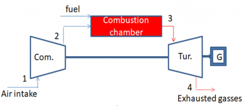
Gas turbine systems are generally transforming thermal fuel energy into mechanical output. Plants that transform thermal energy into mechanical energy through the burning of fuels are known as gas turbine systems. To meet the electrical needs of homes, businesses, and factories, the mechanical energy powers a generator, which in turn feeds electricity into the national grid via distribution power lines. A gas turbine differs from other types of engines in that the working fluid is always flowing through it. In order for air to enter the combustion chamber [1], it must first undergo temperature and pressure compression via an axial or centrifugal compressor, or both (Figure 1(a)). The overall performance can be greatly affected by numerous critical aspects, such as the following: Compression ratio, ambient temperature and pressure, humidity, temperature at the turbine inlet [2-4]. Whoever, Ust et al. [5] presented that an increase of just 10 degrees Celsius in the input temperature of a compressor, for instance, can diminish the power output of various gas turbines by 7 to 11 percent. Therefor this study describes the impact of temperature settings as illustrated in Figure 1(b), where a temperature-entropy (T-S) curve that the functioning of a basic open-cycle gas turbine unit. To clarify how temperature impacts, The diagram shows that the work done by the compressor increases as the ambient temperature rises. The rising contours of the constant-pressure areas inside the compressor demonstrate this (1-4). A decrease in the compressor's output pressure is thus likely to happen if the air temperature outside continues to climb. Furthermore, the air's density keeps decreasing as its temperature keeps rising when it enters the compressor. Because of this, the mass flow rate drops, which in turn reduces the power output.
(a) Flow chart
(b) Temperature of the corresponding T-S diagram
Figure 1. Simulated gas power plant model
To overcome the effect of temperature, especially in high ambient temperature conditions, several studies [6-31] have investigated methods to improve gas turbine cycle performance. Like Alhazmy and Najjar [6] There was an effort to find out how a gas turbine would fare in extremely hot and humid environments. a rise in output power of10% in cold humid conditions and an increase of 18% in hot humid conditions were observed, a 0.57% increase for every 10 degrees Celsius decrease in ambient air temperature. While Lamfon et al. [7] gained a 2% in thermal efficiency, a 1% decrease in specific fuel consumption, and an 11% increase in power generation when cooled air was fed into the compressor inlet. This objective can be accomplished by employing a range of cooling strategies. Air conditioners that evaporatively cool, mechanically chill, or absorb heat are the most efficient. Additional technological benefits and more alternatives for system performance strategy selection are provided by ice storage, which is another option to consider [8-10]. Gas turbine power plants' increasing efficiency was the subject of research by Shukla and Singh [11-13], who looked at the effects of film cooling, steam injection, and intake air cooling. While comparing models that were applicable to the film cooling technique, Mishra and Sanjay [14, 15] came up with a new model for gas turbine blade cooling that could be used to evaluate the mass fraction of blade coolant. According to Mohanty et al. [16] as referenced in Intake air cooling using an absorption chiller was the subject of an analysis about the efficiency of gas turbine cycles. Results showed that the same gas turbine power plant could produce 11% more electricity after reducing the ambient air temperature of the cycle input to 15 degrees Celsius, an increase of 8-13% in power production. When studying the efficiency of a basic gas turbine cycle in a hot and humid environment, Shukla et al. [17] relied on vapour compression inlet air cooling. Results show that ambient air temperature significantly affects the cycle's efficiency. For every 1 degree Celsius increase in air temperature, the specific work production of the cycle decreased by 0.5-0.9 percentage points, to be more exact. nonetheless, El-Shazly and his group of to test [18] how well a gas turbine that ran on natural gas performed, thermodynamic simulations were utilised. In both cases, they compared the results to a baseline without and with an input air conditioning system. Evaporative and absorption cooling methods were both studied. The study found that an absorption chiller with a regenerator may raise power production and efficiency by 25.47% compared to an evaporative cooler, which can boost both values by 5.56% and 1.55%, respectively. In addition, a power system for evaporatively cooled steam-injected gas turbines was evaluated by Shukla and Singh [19]. Optimal intake evaporative cooling, steam injection, and film cooling were the targets of this study, which aimed to improve the power output of a basic gas turbine cycle. Findings demonstrated a 3.2% improvement in thermal efficiency at a steam-to-air ratio of 5% when the compressor inlet temperature was lowered. According to the study, one possible approach to improve efficiency and power output is to combine film cooling, steam injection, and input evaporative cooling. Bidi and Noroozian [20] In order to reduce the intake temperature of the gas turbine unit, research was conducted on the usage of a mechanical chiller that was powered by a natural gas turbo-expander. The impact of input air cooling systems on plant efficiency was investigated using thermodynamic and energetic simulations. In hot weather conditions, the results demonstrated a 3.2% decrease in temperature, an improve in net output power, and a 1.138% improvement in thermal efficiency after the installation of a cooling system. Mohapatra and Sanjay [21] analyzed data from the vapour absorption inlet air cooling system. According to the study's predictions, the combustion chamber is where the majority of the system's exergy loss happens and total exergy destruction reduced as the compressor intake temperature was dropped and the temperature that inlet to turbine was raised. The exergy destruction of all components is negatively affected by both ambient temperature and relative humidity, it was also found. Research on a technology for hybrid inlet air cooling, which combines evaporative units with mechanical chillers, was carried out by Al-Ansary et al. [22]. According to the results, this method might boost the gas turbine's output power by 10%. Another study looked at the possibility of a ground-to-air heat exchanger cooling the air before it entire to the compressor [23]. After implementing this cooling system, the results demonstrated a 4.8 percent increase in thermal efficiency and a 9.0 percent boost in output power. In their study, conducted in Riyadh, Baakeem et al. [24] compared the impact of different input air conditioning systems on gas turbine performance metrics. We advised the ideal intake temperature and cooling capacity. In comparison testing, the researchers demonstrated that both the multi-stage mechanical vapour compression refrigeration system and the single-effect LiBr-H2O absorption system operated admirably. Deng et al. [25] look into the effects of cooled intake air on Combined Cycle Power Plant efficiency. The results showed that the fogging cooling system improved the CCPP performance by up to 17%. However, a very smaller performance boost of only 4% was achieved with the usage of evaporative cooling.
Sohani et al. [26] looked at the potential efficiency gains from installing an indirect evaporative cooler in a gas turbine power plant. After a cooler was added to Iran's Montazer Ghaem power plant, researchers there found that annual net electricity generation went up by 6.02%. Abdel Rahman et al. [27] used a solar-assisted absorption chiller to boost an already effective intake air cooling setup. In Dhahran, KSA, they tested the efficiency of a combined] power plant with and without a new cooling system, as well as with a traditional absorption chiller. Monthly net output power was evaluated to see how the surrounding air affected it. In July, the numbers revealed a decline in production power from the previous month, from 267.878 MW to 226.361 MW. The combined net output power of a conventional chiller plus a solar-assisted chiller was found to be 34.964 MW (or 37.999 MW). The study conducted by Barigozzi et al. [28] Researchers in Phoenix, New Orleans, and Abu Dhabi (UAE) looked at the technical and financial aspects of thermal energy storage in gas turbine combined-cycle power plants. The findings indicate that capital cost increases in wet regions due to the demand of higher thermal storage. Locations with high temperatures and low relative humidity (RH) also fare better economically and technologically year-round. Where Fallah et al. [29] conducted an extensive study on the steam injection gas turbine cycle, to find out what part each part plays and how they interact with each other to destroy exergy in the steam injection gas turbine with an evaporative inlet air cooler cycle, the researchers used complicated exergy analysis and compared it to other cycles, such as the simple gas turbine and the gas turbine with evaporative inlet air cooler. The impact of inlet air cooling on the operation of a real-world gas turbine power facility in Nigeria was investigated by Oyedepo and Kilanko [30]. The findings reveal that the plant's net output power increased by approximately 5-10% for every 5℃ drop in incoming air temperature. Additionally, the building's thermal efficiency increased by a small margin. Taking into account the local climate conditions, Ahmadzadeht and Rashidi [31] undertook a simulation to assess the possible enhancements to the performance of gas turbine power plant unit in Iran. Throughout the course of a year of operation, the study carefully analysed the effects of several inlet air cooling systems, including evaporative media, fogging, mechanical chillers, and thermal energy storage. According to the results, the power generated improved by around 10.62% when a mechanical chiller was installed.
Utilising exergy in analytical studies has recently become more popular, with a focus on calculating losses in each component of the system [32-35], and it found that the maximum exergy destruction accurses in the combustion chamber [36, 37].
This study focuses on improving Iraqi power plants during hot summers to enhance efficiency. It investigates how changes in ambient air temperatures and humidity affect the performance of gas turbine cycles with upstream inlet air cooling. This approach aims to address challenges such as limited capacity and high production costs. The study also highlights the potential of exergy analysis for a comprehensive evaluation of gas power plant performance.
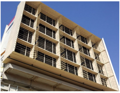
The upstream cooling system (UpS) is ideal for retrofit installations, offering an efficient solution without the need for expensive filter house modifications. The system reduces the risk of water or foreign objects damaging the compressor and does not require on-site water treatment. The cooling process of the system involves two key steps:
Water Spray: Air is first passed through a fine mist of water. This step facilitates cooling through evaporative cooling, where the water absorbs heat from the air as it evaporates.
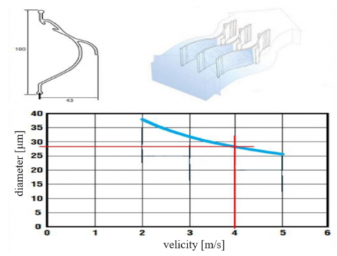
Mesh Media: Following the water spray, the air flows through a large surface area of mesh media known as the Upstream Mesh. This mesh is constructed from carbon-stabilized Polypropylene (PP) and is manufactured using injection molding. The Upstream Mesh serves to separate water droplets from the air, preventing them from entering the filter. This ensures that the air remains clean and does not cause damage to the filter or other system components. Injection molding is employed to create a precise and durable mesh media for the system. A droplet separator downstream of the Upstream Mesh ensures that no liquid water enters the air intake. The droplet separator, also made of carbon-stabilized PP, is manufactured using an extrusion process with profiles spaced at 30 mm intervals. The airflow with liquid droplets must follow the curvature of the profiles, but the droplets, due to their stronger inertia force, collide with the profiles and are drained out. The goal is to remove all droplets larger than 28 mm, which requires an air velocity of over 4 m/sm2 [38], as shown in Figure 2.
In the Al-Khairat Gas Power Plant with a GE Frame 9E, the nominal air flow rate is 336 m3/s. The Upstream Mesh has a calculated area of 122.3 m2, resulting in an air velocity of 2.75 m/s. To meet the requirement that the area of the droplet separator must be smaller than 84 m2, the droplet catcher area is reduced to 81.1 m2, as shown in Figure 3, resulting in an air velocity of 4.1 m/s [38]. The upstream cooling system faces operational challenges such as maintenance, scaling, and water quality requirements. These challenges are managed through specific design elements that ease maintenance and reduce scaling problems. diameter [μm].
Figure 2. The upstream droplet separator
Figure 3. Al-Khairat gas power plant unit with upstream cooling system
Maintenance: Regular upkeep is vital for the USCS's effective functioning. This involves cleaning the mesh media and ensuring unobstructed water spray nozzles. The system is designed with accessible points and removable components to simplify maintenance tasks, allowing maintenance staff to inspect and clean the system efficiently.
Scaling: Scaling happens when minerals in the water accumulate on the system's surfaces, decreasing its efficiency. The USCS is designed with features like mesh filters and water treatment systems to prevent scaling. Mesh filters remove large particles from the water, reducing scaling risks. Additionally, water treatment systems treat the water before it is sprayed, preventing mineral buildup.
Water Quality: Water quality is critical for the USCS's efficient operation. Poor water quality can result in scaling, corrosion, and other problems. To ensure water quality, the system is equipped with filtration and treatment systems. These systems eliminate impurities from the water, guaranteeing that only clean water is used in the cooling process. and it requires 1.7 liters/s of water. These challenges are addressed through design features that enable easy maintenance, external access for cleaning, and mesh filters to prevent scaling. The system's water consumption varies based on size and operating conditions but is generally efficient compared to traditional evaporative systems. Environmental and economic implications include the need for water treatment and disposal, but the system's energy savings and improved efficiency can offset these costs.
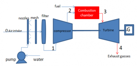
The paper details a gas turbine mathematical model that incorporates an upstream cooling system (UpSC). It measures how well the system works in comparison to a regular gas turbine that doesn't use upstream air cooling. Among the many assumptions made by the model regarding the plant's efficiency and operation is the effect of Wet Bulb Temperature (WBT) on air saturation. The UpSC is a power plant-based system that uses evaporative cooling to cool hot, dry surroundings. It improves comfort and has the ability to increase gas turbine power by as much as 12% [39] by cooling the air using the latent heat of vaporisation.
According to the model:
3.1 Energy analysis
The mass balance equation, when applied across the boundary of the up stream control volume, yields [40].
$\omega_{a, e}=\omega_{a, i}+m_w$ (1)
Figure 4. Displays a simplified illustration of an upstream cooling system for a gas turbine cycle
Figure 5. A process on the psychometric chart
Figure 4 shows how the incoming air temperature can be estimated after cooling [40]:
$T_1=T_{b 0}+\varepsilon *\left(T_{b 0}-T_{w 0}\right)$ (2)
where, Tb0 is dry bulb temperature, Tw0 is wet bulb temperature, in addition, is the efficiency of cooling system.
The UPSC system's cooling requirements cause [41]:
$Q_{\text {cooling }}=\dot{m_a} * c_{p, a}\left(T_0-T_1\right)$ (3)
wherever, a $\dot{m_a}$ is air mass flow rate.
$\rho=p[1] /\left(0.287 * T_1\right)$ (4)
$\dot{\mathrm{m}}_{\mathrm{a}}=\rho *(\dot{\mathrm{V}})[\mathrm{kg} / \mathrm{s}]$ (5)
From this psychometric chart (see Figure 5), we may calculate the total enthalpy of the air in the atmosphere. assuming an isentropic efficiency $\eta_c\ \&\ \eta_T$ and using the ideal gas relation, the fluid's exit temperature from the compressor T2 and from the turbine T4 can be calculated according the following equation [41]:
$\left[r_p^{\frac{\gamma}{\gamma-1}}-1\right]$ (6)
$T_2=T_1+\frac{T_1}{\eta_{c, i s}}$
$\mathrm{T}_4=\mathrm{T}_3 *\left(1-\eta_{\mathrm{T}, \mathrm{is}} *\left(1-\mathrm{r}_{\mathrm{p}}(1-\gamma) / \gamma\right)\right.$ (7)
However, in our project, the value of compression ratio (rp) was evaluated from experimental testing of Al-Khairat system according to the following equation.
$\mathrm{r}_{\mathrm{p}}=9+(3 / 50) *\left(50-\mathrm{T}_1\right)$ (8)
$\dot{\mathrm{W}}_{\mathrm{c}}=\dot{\mathrm{m}}_{\mathrm{a}} * \mathrm{C}_{\mathrm{pa}} *\left(\mathrm{~T}_2-\mathrm{T}_1\right) / \mathrm{\eta} \mathrm{c}$ (9)
γ the specific heat ratio γ =Cpg/Cvg.
The total mass flow rate of moist air is specified [39]:
$\dot{m}_{h a}=\dot{m}_{d a}+\omega \dot m_{d a}=(1+\omega) \dot{m}_{d a}$ (10)
Using mass flow rate also enthalpy change across compressor, one may determine the amount of effort required to compress humid air traveling between states [41]:
$W_c=\dot{m}_a(1+\omega) * c_{p a}\left(T_{2 s}-T_1\right)+\omega\left(h_{2 s}-h_1\right)$ (11)
The turbine's output of energy, gained by the expansion of heated gases, is defined as [41]:
$W_T=\dot{m}_t * c_{p g}\left(T_3-T_4\right)+\omega\left(h_3-h_4\right)$ (12)
$\dot{m}_t=\dot{m}_a+\dot{m}_v+\dot{m}_f=\dot{m}_a(1+\omega+f)$ (13)
where, $f=\frac{\dot{m}_f}{\dot{m}_a}$.
The electric power produced by the gas turbine is expressed as [41]:
$\dot{W}_{\text {net }}=\dot{W}_T-\dot{W}_c$ (14)
The thermal efficiency of the gas turbine is provided as [41]:
$\eta_{t h}=\frac{\dot{W}_{n e t}}{\dot{\mathrm{Q}} c c}$ (15)
The calculation of specific fuel consumption for a gas turbine involves:
$\mathrm{SFC}=\frac{3600 * \dot{m}_f}{\dot{W}_{\text {net }}} {kg} / {kWh}$ (16)
3.2 Exergy analysis
An exergy analysis is a method of assessing the effectiveness and durability of energy conversion processes. It examines the energy quality and availability within a system and detects points where energy is lost or wasted. By identifying these areas, exergy analysis helps to enhance the efficiency of energy systems and reduce energy waste and losses. The exergy equations [40]:
$\sum \dot{\mathrm{m}}_i=\sum \dot{\mathrm{m}}_e$ (17)
$\mathrm{Q}-\mathrm{W}=\sum \dot{\mathrm{m}}_{\text {out }} \mathrm{h}_{\text {out }}-\sum \dot{\mathrm{m}}_i \mathrm{~h}_i$ (18)
$\mathrm{E}_Q+\sum_{ {in }} \mathrm{ \dot mX}_{\text {in }}=\dot{\mathrm{W}}+\sum_{ {out }} \dot{\mathrm{m}} X_{ {out }}+E_d$ (19)
$\sum\left(1-\frac{\mathrm{To}}{\mathrm{T}}\right) Q+\sum_{ {in }}(\dot{\mathrm{m}} \mathrm{X})_{ {in }}=\dot{\mathrm{W}}+\sum_{ {out }}(\dot{\mathrm{m}} \mathrm{X})_{ {out }}+E_{{d }}$ (20)
3.2.1 Upstream cooling system
An upstream cooling system is a device utilized in a gas turbine power plant toward a lower temperature of the incoming air before reaching the compressor stage. Its purpose is to improve the overall performance, efficiency, and power generation capability of the gas power plants.
$X_{u p 1}-X_{u p 0}=\dot{m}_{\text {air }}(1+\omega) c_p\left(T_1-T_0\right)+\omega\left(h_1-h_0)\right.$ (21)
$\left(\dot{m}_{\text {air }} T_o\left(S_1-S_0\right)+\dot{m}_w T_o\left(S_{1 w}-S_{0 w}\right)\right)$ (22)
$Q=\dot{m}_{\text {air }}(1+\omega) c_p T_1-\dot{m}_{\text {air }} c_p T_0+\omega\left(h_1-h_0\right)$ (23)
3.2.2 Compressor
A compressor is a mechanical apparatus that boosts the pressure of a gas by decreasing its volume. It compresses incoming air to high pressures prior to its entry into the combustion chamber.
$\begin{gathered}X_{c 2}-X_{c 2}=\dot m_{\text {air }}(1+\omega) c_{p a}\left(T_2-T_1\right)+\omega\left(h_{2 s}-h_1\right) \\ -\left(m_{\text {air }} T_o\left(S_2-S_1\right)+\dot{m}_w T_o\left(S_{2 w}-S_{1 w}\right)\right)\end{gathered}$ (24)
where, $S_2-S_1=c_{p a} \ln \left(\frac{T_2}{T_1}\right)-\mathrm{R} \ln \left(\frac{P_2}{P_1}\right)$.
The exergy destruction rate in the air compressor:
$X_d=W_c+X_{c 1}-X_{c 2}$ (25)
The specific heat capacity is obtained by polynomial form as a function of temperature given by:
$c_{p, a v}=\alpha+\beta \mathrm{T}+\gamma T^2+\delta T^3$ (26)
The values of, β, γ, and δ are constant features of considered gas obtained from standard tables.
3.2.3 Combustion chamber
The combustion chamber in a gas turbine power plant is where the process of combustion occurs. It is a critical component where fuel is mixed with compressed air and ignited to produce high-temperature, high-pressure gases that drive the turbine. We assume that crude oil is heavy diesel fuel, The combustion of heavy diesel fuel can be represented by the following balanced chemical equation:
$\begin{aligned} & \mathrm{C}_{14.6} \mathrm{H}_{24.8}+21\left(\mathrm{O}_2+3.76 \mathrm{~N}_2\right) \rightarrow 14.6 \mathrm{CO}_2+12.4 \mathrm{H}_2 \mathrm{O} +21\left(3.76 \mathrm{~N}_2\right)\end{aligned}$ (27)
$X_f+X_{2 p h}+X_{2 c h}=X_{3 p h}+X_{3 c h}+E_d$ (28)
where, $\phi=\frac{x_f}{L H V}$.
$\begin{gathered}X_{2 p h}=\dot{\mathrm{m}}_t c_{p g}\left(T_2-T_1\right)+\omega\left(h_2-h_1\right)-T_0\left[c_{p g} \ln \left(\frac{T_2}{T_1}\right)\right. \left.\mathrm{R} \ln \left(\frac{P_2}{P_1}\right)\right]\end{gathered}$ (29)
$\begin{gathered}X_{3 p h}=\dot{\mathrm{m}}_t c_{p g}\left(T_{3-} T_1\right)+\omega\left(h_3-h_1\right)-T_0\left[c_{p g} \ln \left(\frac{T_3}{T_1}\right)-\right. \left.\mathrm{R} \ln \left(\frac{P_3}{P_1}\right)\right]\end{gathered}$ (30)
$X_{c h}=\left(\mathrm{A}^* x_f\right)+\left(\left(\dot{\mathrm{m}}_{\mathrm{g}}-\mathrm{A}\right) x_a\right)$ (31)
where, A =(AFa-AFth) * ṁf and AFactual=ṁa/ṁf.
$\mathrm{Q}=\dot{m}_{\text {air }}(1+f)\left(c_{p, g} T_3-c_{p a} T_2\right)$ (32)
3.2.4 Turbine
Gas Turbine: A gas turbine is the primary component of a gas power plant, which converts the chemical energy of natural gas into mechanical energy. The gas turbine's energy analysis includes evaluating its efficiency, which is typically around 30-40% for modern gas turbines.
$\begin{gathered}\dot{X}_{T 3}-\dot{X}_{T 4}=\dot{m}_{\text {air }}(1+\omega+f) c_{p g}\left(T_3-\right. \left.T_4\right)+\omega\left(h_{3 s}-h_4\right)\\-\left(\dot{m}_{\text {air }} T_o\left(S_3-S_4\right)+\dot{m}_w T_o\right. \left.\left(S_{3 w}-S_{4 w}\right)\right)\end{gathered}$ (33)
Table 1. Reference data and assumptions
|
Parameter |
Value |
|
ISO condition |
15℃, 60%RH, 101.3 kpa |
|
Η(com,T)is |
0.95 |
|
ηT |
0.9 |
|
ηG |
0.95 |
|
η com |
0.8 |
|
V |
336 m3/s |
|
Ε |
0.7% |
|
Fuel |
Heavy diesel |
|
LHV |
42500 kJ/kg |
|
Firing temperature |
1280 k |
|
AFth |
15.6% |
|
Exergy ratio |
1.04 |
$E_{d T}=X_{T 3}-X_{T 4} W_T$ (34)
The exergy efficiency of the gas power plant is given as:
$\eta_{\text {II }}=\frac{\dot{\mathrm{W}}_{\text {net }}}{\dot{\mathrm{X}}_{\mathrm{f}}}$ (35)
The mathematical model was initialized using EES, real data from the Al Khairat Gas Power Plant was input, and the model was run to perform energy and exergy analyses, calculating compressor and turbine efficiencies and pressure ratios, as shown in Table 1 with the reference data and assumptions.
3.3 Validation
The model's predictions were validated by comparing them with experimental data from Al-Khairat gas turbine systems with an upstream cooling system. The comparison showed that the model closely matched the experimental results for power output, mass flow rate, and temperatures, validating its accuracy (Table 2).
Table 2. Al-Khairat experimental data and EES program data with upstream cooling system
|
T0 (k) |
313 |
318 |
323 |
328 |
|
|
$\dot{\mathrm{W}}_{\text {net }}$ (MW) |
Model |
89.33 |
87.34 |
85.79 |
84.82 |
|
experimental |
90 |
88 |
86 |
85 |
|
|
$\dot{m}_f$ (Kg/s) |
Model |
6.95 |
6.88 |
6.82 |
6.79 |
|
experimental |
6.9 |
6.8 |
6.8 |
6.7 |
|
|
T1 (K) |
Model |
300.4 |
302.8 |
304.6 |
305.8 |
|
experimental |
301 |
304 |
305 |
307 |
|
|
T2 (K) |
Model |
609.6 |
611.8 |
613.4 |
614.5 |
|
experimental |
612 |
614 |
615 |
619 |
|
|
T4 (K) |
Model |
791.5 |
793.7 |
795.4 |
796.5 |
|
experimental |
790 |
792 |
795 |
798 |
|
The model in this study has limitations, relying on simplifying assumptions and idealized conditions for gas turbine and cooling system representations. Its accuracy hinges on input data accuracy and assumption validity. The model's scope is specific, potentially overlooking real-world complexities. While validated against experimental data, its validation is constrained by specific conditions and data sets. Lastly, its complexity may require a deep understanding for use.
The model proposed for analyzing gas turbine performance with an upstream cooling system (UpSC) has practical applications in real-world scenarios. Engineers and operators can use it during the design phase of gas turbine power plants to optimize UpSC configurations. By inputting parameters such as ambient temperature, humidity, and turbine specifications, the model can predict improvements in efficiency, power output, and specific fuel consumption (SFC) resulting from UpSC implementation.
Moreover, the model can assist in operational decision-making. Operators can assess the impact of different operating conditions on UpSC performance, aiding in decisions regarding system operation, maintenance schedules, and potential upgrades. For instance, the model can determine the most efficient UpSC operation settings based on current environmental conditions, maximizing performance while minimizing energy consumption and operational costs.
Machines operating at a fixed speed maintain a consistent airflow rate. However, with rising ambient temperatures, the density of air decreases, leading to a decrease in the mass passing through the machine and an increase in the compression ratio. Therefore, the output power drops.
In this study, we used the Engineering Equation Solver (EES) computer code to evaluate the gas turbine's energy and exergy performance, and we used relative humidity values that are proportional to temperature and are close to the actual standards in Iraq. The resulting outcomes were subsequently compared to the actual performance values of a GE MS9001E model, both with and without an upstream cooling system.
4.1 Compressor inlet temperature versus ambient temperature
In Figure 6, the inlet temperature of the compressor is displayed when a UPSC system is employed. The upstream cooler reduces the ambient air temperature to a point where it is nearly identical to the wet bulb temperature. A direct correlation exists between the upstream cooler's efficiency and the degree to which the wet bulb temperature and the compressor inlet temperature match. The temperature at which the compressor takes in air must never exceed that of the wet bulb, regardless of how near the two temperatures are.
Figure 6. Temperature at the compressor's inlet against outside temperature with and without an upstream cooling system
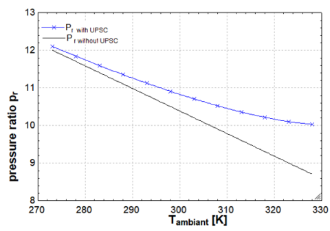
Figure 7. Comparing the pressure ratio with and without an upstream cooling device as the ambient air temperature varies
4.2 Pressure ratio versus ambient temperature
Pressure ratio and ambient temperature are inversely related, as can be seen from the data in Figure 7. There is a negative pressure ratio when the surrounding temperature rises. On the other hand, a higher pressure ratio is observed when a (UPCS) is used.
4.3 The impact of changes in ambient air temperature on the output power
In each case, we tested Al-Khirat gas turbine's output power at varying ambient temperatures to see how effective an upstream cooler was. Figure 8 shows that the gas turbine's output power was enhanced by lowering the intake air temperature using the upstream cooler.
Figure 8. The impact of changes in ambient air temperature on the output power with and without an up stream cooling system
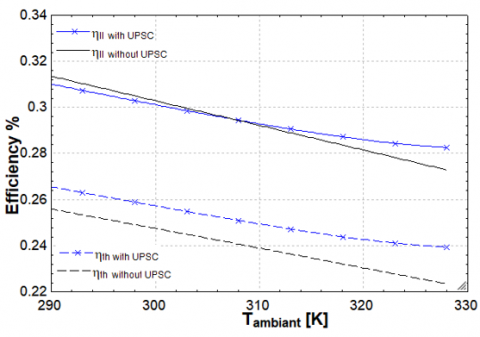
4.4 The effect of changes in ambient air temperature on the thermal and exergy efficiency
From ISO circumstances (T=15C), the gas turbine's thermal and exergy efficiency significantly decreases as the ambient air temperature rises. At a temperature of 320 k, an upstream cooler improves thermal efficiency by 5.2% and exergy efficiency by 2.51%. As can be seen in Figure 9, the thermal efficiency failed to capture the true nature of gas turbine performance when upstream cooling systems were included. This disparity raises the possibility that exergy efficiency or particular fuel usage might be better indicators of UPCS's effect on total efficiency.
Figure 9. The effect of changes in ambient air temperature on the thermal and exergy efficiency with and without an up stream cooling system
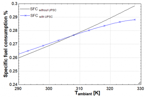
4.5 The influence of changes in ambient air temperature on the specific fuel consumption
Specific fuel consumption is a way to quantify the quantity of fuel utilised in power generation. The output of the gas turbine decreases as the ambient temperature increases. Consequently, the particular fuel consumption of the gas turbine increases. However, in the case of a gas turbine with an upstream cooling system (UPSC), Figure 10 illustrates that the UPSC initially has a negative impact on SFC below 310K due to increased fuel usage exceeding the net power increase. However, above this temperature, the UPSC significantly improves performance by decreasing SFC, with a 17.5% decrease observed at 320K.
Figure 10. The effect of changes in ambient air temperature on the specific fuel consumption with and without an upstream cooling system
(a) without an upstream cooling system
(b) with an upstream cooling system
Figure 11. Effect of changes in ambient air temperature on exergy destruction
4.6 Observations of significant destruction in combustion chamber, compressor, turbine and exhaust gasses
Figure 11(a) presents the destruction observed in the Gas turbine system, including the combustion chamber, compressor, and turbine, in addition to the exergy loss to the environment by hot gasses, at different ambient temperatures. Comparing the three components, it is evident that the hot gasses and combustion chamber experience more significant destruction compared to the compressor and turbine. Furthermore, it is observed that the destruction in the hot gasses decreases as ambient temperature increases. However, when a gas turbine utilizes a (UPSC) Figure 11(b), the intake air temperature is cooled. This cooling effect leads to a high decrease in the hot gasses destruction with little increase in a combustion chamber leading to a high drop in all destruction.
The changes in performance, especially the notable decrease in efficiency and power output as the inlet air temperature rises, underscore the crucial influence of ambient conditions on gas turbine functionality. These changes can be evaluated against industry norms and anticipations:
Efficiency Decline: The substantial reductions of 11.5% in thermal efficiency and 11.2% in exergy efficiency with a 35 K increase in inlet air temperature are noteworthy. While some efficiency decline in hotter conditions is expected, these decreases may exceed typical industry standards. This suggests either a heightened sensitivity to ambient conditions in this turbine or a requirement for more efficient cooling mechanisms.
Power Output Reduction: The 27.4% decrease in power production with rising temperature is significant. While some power loss is anticipated in higher temperatures, this reduction may be more pronounced than average. This highlights the critical role of effective cooling systems in sustaining power output in hot environments.
Impact of Upstream Cooler System: The introduction of the upstream cooler system, leading to a 15 MW increase in power output, is impressive. While specific figures can vary based on turbine models and setups, a 15 MW enhancement represents a substantial improvement, showcasing the cooling system's effectiveness in boosting performance.
Efficiency Gains with Cooler System: The thermal efficiency improved by 5.2%, and there was a 2.5% increase in exergy efficiency. with the cooler system are positive outcomes. These enhancements align with expected benefits of such systems, indicating the effective operation of the cooler system in improving overall turbine performance.
When the air temperature around the gas turbine rises, the turbine's efficiency drops dramatically. Power production drops by 27.4 percent, thermal efficiency drops by 11.5 percent, and exergy efficiency drops by 11.2 percent when inlet air temperature rises by 35 K. Ambient temperature was kept at 320k and relative humidity was kept at 15% to facilitate extensive testing across a wide temperature range. The gas turbine has an output power of 72 MW without upstream inlet cooling. A significant boost of 15 MW is achieved when an upstream cooler system is added, bringing the total output power to 87 MW. A gain of 5.2% in thermal efficiency and 2.5% in exergy efficiency.
Practical Implications and Recommendations: The results of the study have practical implications concerning gas turbine operation in hot, dry climates like Iraq. It is recommended to use high-efficiency, low-cost cooling systems tailored to Iraq's climate to mitigate the impact of dry and high temperatures on gas turbine performance.
Future Research Directions: Future research should focus on advanced, low-cost cooling techniques to enhance cooling efficiency and mitigate the impact of high ambient temperatures in hot, dry climates. These efforts can contribute to the development of more efficient and affordable gas turbine systems for such environments.
|
A |
access air |
|
AF |
air to fuel ratio |
|
CP |
specific heat at constant pressure, kJ/kg K |
|
Ėd |
exergy destruction |
|
h |
enthalpy, kJ/kg |
|
LHV |
fuel lower heating value, kJ/kg |
|
ṁ |
mass flow rate, kg/s |
|
QU |
Up-stream heat, kW |
|
R |
universal gas constant, kJ/kg K |
|
RH |
relative humidity, % |
|
rp |
pressure ratio |
|
S |
entropy |
|
SFC |
specific fuel consumption, kg/kW h |
|
T |
temperature, K |
|
V |
volumetric flow rate, m3/s |
|
W |
work, kW |
|
Ẋ |
exergy |
|
γ |
The specific heat ratio |
|
ΔPinlet |
inlet pressure loss, N/m2 |
|
Greek symbols |
|
|
ε |
UPSC effectiveness |
|
η |
efficiency |
|
ηII |
energy efficiency |
|
ρ |
density, kg/m3 |
|
ϕ |
exergy ratio |
|
ω |
moisture content, kgvapor/kgair |
|
Subscripts |
|
|
1 |
across comp |
|
2 |
across turbine |
|
a |
actual, air, average |
|
com |
compressor |
|
cc |
combustion chamber |
|
da |
dry |
|
db |
dry bulb |
|
e |
exit |
|
f |
fuel |
|
g |
exhaust gasses |
|
ha |
humid |
|
is |
isentropic |
|
loss |
hot gasses |
|
T |
turbine |
|
tot |
total |
|
w |
water |
|
wb |
wet bulb |
|
Abbreviations |
|
|
UPSC |
stream cooling system |
|
ISO |
International Organization for Standard |
[1] Xeon, L. (2022). Improved efficiency of a gas turbine. Journal of Research and Applications in Mechanical Engineering, 11(5): 419. https://doi.org/10.35248/2168-9873.22.11.419
[2] Davarpanah, A. (2018). Feasible analysis of reusing flowback produced water in the operational performances of oil reservoirs. Environmental Science and Pollution Research, 25: 35387-35395. https://doi.org/10.1007/s11356-018-3506-9
[3] Kakaras, E., Doukelis, A., Prelipceanu, A., Karellas, S. (2006). Inlet air cooling methods for gas turbine-based power plants. Journal of Engineering for Gas Turbines and Power, 128(2): 312-317. http://doi.org/10.1115/1.2131888
[4] Oyedepo, S.O., Fagbenle, R.O., Adefila, S.S., AlamInstitute, M.M., Pham, D. (2015). Exergy costing analysis and performance evaluation of selected gas turbine power plants. Cogent Engineering, 2(1): 1101048. http://doi.org/10.1080/23311916.2015.1101048
[5] Ust, Y., Arslan, F, Ozsari, I., Cakir, M. (2015). Thermodynamic performance analysis and optimization of DMC (Dual Miller Cycle) cogeneration system by considering exergetic performance coefficient and total exergy output criteria Energy, 90(p1): 552-559. https://doi.org/10.1016/j.energy.2015.07.081
[6] Alhazmy, M.M., Najjar, Y.S.H. (2004). Augmentation of gas turbine performance using air coolers. Applied Thermal Engineering, 24(2-3): 415-429. https://doi.org/10.1016/j.applthermaleng.2003.09.006
[7] Lamfon, N.J., Najjar, Y.S.H., Akyurt, M. (1998). Modeling and simulation of combined gas turbine engine and heat pipe system for waste heat recovery and utilization. Energy Conversion and Management, 39(1-2): 81-86. https://doi.org/10.1016/S0196-8904(96)00175-6
[8] Comodi, G., Renzi, M., Caresana, F., Pelagalli, L. (2015). Limiting the effect of ambient temperature on micro gas turbines (MGTs) performance through inlet air cooling (IAC) techniques: An experimental comparison between fogging and direct expansion. Energy Procedia, 75: 1172-1177. https://doi.org/10.1016/j.egypro.2015.07.561
[9] Gareta, R., Romeo, L.M., Gil, A. (2004). Methodology for the economic evaluation of gas turbine air cooling systems in combined cycle applications. Energy, 29(11): 1805-1818. https://doi.org/10.1016/j.energy.2004.03.040
[10] Alhazmy, M.M., Najjar, Y.S.H. (2004). Augmentation of gas turbine performance using air coolers. Applied Thermal Engineering, 24(2-3): 415-429. https://doi.org/10.1016/j.applthermaleng.2003 .09.006
[11] Shukla, A.K., Singh, O. (2016). Performance evaluation of steam injected gas turbine-based power plant with inlet evaporative cooling. Applied Thermal Engineering, 102: 454-464. https://doi.org/10.1016/j.applthermaleng.2016.03.136
[12] Shukla, A.K., Singh, O. (2017). Thermodynamic analysis of steam-injected gas turbine cycle power plant with inlet air cooling. International Journal of Ambient Energy, 38(6): 556-566. https://doi.org/10.1080/01430750.2016.1155495
[13] Shukla, A.k., Singh, O. (2017). Thermodynamic investigation of parameters affecting the execution of steam injected cooled gas turbine based combined cycle power plant with vapor absorption inlet air cooling. Applied Thermal Engineering, 122: 380-388. https://doi.org/10.1016/j.applthermaleng.2017.05.034
[14] Mishra, S., Sanjay, Y. (2017). Parametric analysis of aero-derivative gas turbine: effect of radiative heat transfer on blade coolant requirement. SAE Technical Paper 2017-01-2045. https://doi.org/10.4271/2017-01-2045
[15] Mishra, S., Sanjay, Y. (2018). Energy and exergy analysis of air-film cooled gas turbine cycle: Effect of radiative heat transfer on blade coolant requirement. Applied Thermal Engineering, 129: 1403-1413. https://doi.org/10.1016/j.applthermaleng.2017.10.128
[16] Mohanty, B., Paloso, G. (1995). Enhancing gas turbine performance by intake air cooling using an absorption chiller. Heat Recovery Systems and CHP, 15(1): 41-50. https://doi.org/10.1016/0890-4332(95)90036-5
[17] Shukla, A.K., Sharma, A., Sharma, M., Mishra, S. (2018). Performance improvement of simple gas turbine cycle with vapor compression inlet air cooling. Materialstody Proceedings, 5(9): 19172-19180. https://doi.org/10.1016/j.matpr.2018.06.272
[18] El-Shazly, A.A., Elhelw, M., Sorour, M.M., El-Maghlany, W.M. (2016). Gas turbine performance enhancement via utilizing different integrated turbine inlet cooling techniques. Alexandria Engineering Journal, 55(3): 1903-1914. https://doi.org/10.1016/j.aej.2016.07.036
[19] Shukla, A.K., Singh, O. (2016). Performance evaluation of steam injected gas turbine based power plant with inlet evaporative cooling. Applied Thermal Engineering, 102: 454-464. http://doi.org/10.1016/j.applthermaleng.2016.03.136
[20] Noroozian, A., Bidi, M. (2016). An applicable method for gas turbine efficiency improvement. Case study: Montazar Ghaem power plant, Iran. Journal of Natural Gas Science and Engineering, 28: 95-105. https://doi.org/10.1016/j.jngse.2015.11.032
[21] Mohapatra, A.K., Sanjay. (2018). Exergetic evaluation of gas-turbine based combined cycle system with vapor absorption inlet cooling. Applied Thermal Engineering, 136: 431-443. https://doi.org/10.1016/j.applthermaleng.2018.03.023
[22] Al-Ansary, H.A., Orf, J.A., Ali, M.E. (2013). Impact of the use of a hybrid turbine inlet air cooling system in arid climates. Energy Conversion and Management, 75: 214-223. https://doi.org/10.1016/j.enconman.2013.06.005
[23] Barakat, S., Ramzy, A., Hamed, A.M., Emam, S.H.E. (2016). Enhancement of gas turbine power output using earth to air heat exchanger (EAHE) cooling system. Energy Conversion and Management, 111: 137-146. https://doi.org/10.1016/j.enconman.2015.12.060
[24] Baakeem, S.S., Orf, J., Al-Ansary, H. (2018). Performance improvement of gas turbine power plants by utilizing turbine inlet air-cooling (TIAC) technologies in Riyadh, Saudi Arabia. Applied Thermal Engineering, 138: 417-432. https://doi.org/10.1016/j.applthermaleng.2018.04.018
[25] Deng, C., Kosari, E., Al-Sammarraie, A.T., Ibrahim, T.K., Basrawi, F., Ismail, F.B., Abdalla, A.N. (2020). Air cooling techniques and corresponding impacts on combined cycle power plant (CCPP) performance: A review Techniques de refroidissement de l’air et impacts correspondants sur les performances des centrales électriques à cycle combiné. International Journal of Refrigeration, 120: 161-177. https://doi.org/10.1016/j.ijrefrig.2020.08.008
[26] Sohani, A., Farasati, Y., Sayyaadi, H. (2017). A systematic approach to FND the best road map for enhancement of a power plant with dew point inlet air pre-cooling of the air compressor. Energy Conversion and Management, 150: 463-484. https://doi.org/10.1016/j.enconman.2017.08.028
[27] Rahman, A.A.A., Mokheimer, E.M.A. (2017). Boosting gas turbine combined cycle in hot regions using inlet air cooling including solar energy. Energy Procedia, 142: 1509-1515. https://doi.org/10.1016/j.egypro.2017.12.600
[28] Barigozzi, G., Perdichizzi, A., Gritti, C., Guaiatelli, I. (2015). Technoeconomic analysis of gas turbine inlet air cooling for combined cycle power plant for different climatic conditions. Applied Thermal Engineering, 82: 57-67. https://doi.org/10.1016/J.APPLTHERMALENG.2015.02.049
[29] Fallah, M., Siyahi, H., Akbarpour, R., Mahmoudi, S.M.S., Yari, M., Rosen, M.A. (2016). Comparison of different gas turbine cycles and advanced exergy analysis of the most effective. Energy, 116: 701-715. https://doi.org/10.1016/j.energy.2016.10.009
[30] Oyedepo, S.O., Kilanko, O. (2014). Thermodynamic analysis of a gas turbine power plant modeled with an evaporative cooler. International Journal of Thermodynamics, 17(1): 14-20. https://doi.org/10.5541/ijot.76988
[31] Ahmadzadehtalatapeh, M., Rashidi, H.R. (2020). Performance enhancement of gas turbine units by retrofitting with inlet air cooling technologies (IACTs): an hour‑by‑hour simulation study. Journal of the Brazilian Society of Mechanical Sciences and Engineering, 42: 139-168. https://doi.org/10.1007/s40430-020-2216-7
[32] Budiyanto, M., A., Triandi1, A.O., Kurniawan, O. (2020), Study on the thermodynamic cycle of gas engine power plant 10MW. AIP Conference Proceedings, 2227(1): 020006. https://doi.org/10.1063/5.0000962
[33] Hasan, A., Ahmed, A., Hamid, Q.Y. (2020). Exergy and energy analysis of 150 MW gas turbine unit: A case study. Journal of Advanced Research in Fluid Mechanics and Thermal Sciences, 67(1): 186-192. https://www.akademiabaru.com/doc/ARFMTSV67_N1_P186_192.pdf.
[34] Salah, S.A., Abbas, E.F., Ali, O.M., Alwan, N.T., Yaqoob, S.J., Alayi, R. (2022). Evaluation of the gas turbine unit in the Kirkuk gas power plant to analyze the energy and exergy using ChemCad simulation. International Journal of Low-Carbon Technologies, 17: 603-610. https://doi.org/10.1093/ijlct/ctac034
[35] Altarawneh, O., Alsarayreh, A.A., Al-Falahat, A.M., Al-Kheetan, M.J., Alrwashdeh, S.S. (2022). Energy and exergy analyses for a combined cycle power plant in Jordan. Case Studies in Thermal Engineering, 31: 101852. https://doi.org/10.1016/j.csite.2022.101852
[36] Shamoushky, M., Ehyaie, M. (2020). Optimization of the gas power plant by evolutionary Algorithm; considering exergy, economic and environmental aspects. Journal of Thermal Engineering, 6(11): 180-200. https://doi.org/10.18186/thermal.730250
[37] Shamoushaki, M., Ghanatir, F., Ehyaei, M.A., Ahmadi, A. (2017). Exergy and exergoeconomic analysis and multi-objective optimization of gas turbine power plant by evolutionary algorithms Case study: Aiiabad Katoul power plant. International Journal of Exergy, 22(3): 279-230. https://doi.org/10.1504/IJEX.2017.083160
[38] BBM Akustik Technology. (2023). Upstream cooling system, dimensions: Technical reasons for selected overall dimensions of upstream cooling modules in relation to AIS. Internal Document.
[39] Ewa, P., Szymon, J., Andrzej, M. (2012). Impact of inlet air cooling on gas turbine performance. Journal of Energy and Power Technology, 92: 249-257. https://doi.org/10.5541/ijot.76988
[40] Moran, M.J., Shapiro, H.N., Boettner, D.D., Bailey, M.B. (2010). Fundamentals of Engineering Thermodynamics. John Wiley & Sons. https://www.amazon.com/Fundamentals-Engineering-Thermodynamics-Michael-Moran/dp/0470495901.
[41] Çengel, Y.A., Michael, B. (2014). Thermodynamics: An Engineering Approach. McGraw-Hill Education. https://www.amazon.com/Thermodynamics-Engineering-Yunus-Cengel-Dr/dp/0073398179.