Sarah Rabeea Nashee![]()
© 2024 The author. This article is published by IIETA and is licensed under the CC BY 4.0 license (http://creativecommons.org/licenses/by/4.0/).
OPEN ACCESS
In this current work, heat transfer and pressure loss are predicted using a fluid simulation with incompressible flow inside a tube that has been equipped with twisted tape for several tested cases. 2-types of twisted tape cutting tests are included in the set: single - cut and double - cut, with different cut ratios (a/b)=0.3, 0.5, 0.7, and 0.9. Supplied the (k-ε model) in the Ansys Fluent, the simulation was run analytically. The tests were conducted to test the influence of cutting the twisted-tape on the behaivior of flow and the performance enhancing by employing water flows in turbulent by applying Reynold number to measure the fluid's velocity, which ranges from 5000 to 25000. According to the results of the testing, the double-cut case expresses a pressure drop and transfers heat more effectively than the single-cut case; the double-cut case also has higher friction factor values. Regarding the testing of the cutting ratio's effect, the findings indicate that the thermal-performance is rising in relation to the cutting ratio's rise. There were good agreements found in the study's comparison analysis with earlier studies in the same field.
double-cut twisted tape, single-cut twisted tape, twisted tape, cut ratio, turbulent flow
The current tendency is to optimize the performance of thermal applications while conserving energy and materials by improving heat transmission. It is possible to reduce the size and operational costs by implementing these approaches [1-3]. Numerous strategies are used in engineering and thermal applications to improve heat transfer. For example, twisted tapes and tubes have long been used to optimize passive heat transmission in fluid transfer pipes, and heat exchangers. Chemical processing facilities, solar heaters and power plants systems are just a few of the many thermal applications. These insert tools are readily replaceable, readily producible, and easy to remove for maintenance. As a result, several changes are possible, including geometrical shape changes [4-6].
Twisted tapes are essential for thermal systems to enhance heat transfer potential and overall system performance, according to numerous investigations. Later effort, though, was needed to improve this performance by adding to, altering, and other aspects of these tapes to further emphasize their significance [7].
Kumar et al. [8] conducted experiments on fluid behavior using four pipes with twisted-tapes. For a range of velocities and for every tape, there were different twist ratios, which varied from 6 to 15. The gain data showed that the addition of twisted-tape raised the coefficient of heat transfer on a greater pressure drop penalty as opposed to plain pipe. An investigation of a dual-pipe employing (ACT-tape) and typical-T tape for Re ranging from 3000 to 9000 was completed by Man et al. [9]. The outcome showed that, while using an ACCT tape insert, the performance evaluation criteria's maximum values reached 1.4. For (Re) fluctuated between 3000 and 30,000, Prasad and Gupta [10] carried comprehensive studies on the influence of this addition and observed that (Nu) had risen greatly in order to boost the of heat transfer rate in a U-tube with addition twisted-tape. (Nu) had a 31.27% rise. A triple-tape test for spirally twisted tubes was completed by Eiamsa-ard et al. [11]. Testing was also done to determine the effects of width ratio of the tapes.
The acquired results demonstrate that heat transfer raised with the width of the tapes. Furthermore, Hong et. al. [12] finished a numerical work to evaluate the features of turbulent flow in tubes equipped with and without counter--swirling twisted-tapes. Nu and f rowing for the CDT example were found to be approximately 6.3e36.7% and 1.76e5.3 times larger than those for the CDs, respectively, by using tests, Kumbhar and Sane [13] investigated how adding twisted tape in a regularly spaced pattern may improve the friction factor, and heat transmission of a tube with a dented wall. The working medium was flowing water with 4200≤Re≤16000. Through this investigation, the authors discovered that the length (no space) twisted-tape performed better for dimpled tubes than any other tested type of twisted-tape. Also, Hasanpour et al. [14] tested the Nu and f in corrugated tube. The water went through the tube with Re from 5000 to 15000 and was furnished with standard and modified twisted tapes, including perforated types of U and V cuts. The researchers discovered that all T.T cases had higher friction factors and Nusselt numbers than empty cases, and that perforated tape types produced lower f and Nu than normal types.
Sivashanmugam and Suresh [15] established correlations in terms of twist ratio. And for continuation of their research, After Sivashanmugam and Suresh [16] completed their experiments, the data they collected was contrasted with the data that had already been published in the literature. They indicated that there was growing in the value of. performance. raised with decreasing width-ratio and twist-ratio.
Two cases of cutting twisted tape that was introduced into a tube have been carried out, according to the current study (single cutting twisted tape and double cutting twisted tape). There are many cut ratios in the research, ranging from 0.3 to 0.9. Water flows with Re values varying from 5000 to 25000. The purpose of this test is to obtain rising in the thermal-performance.
2.1 Model description
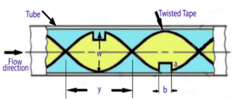
The investigation's schematic-diagram, displays in Figure 1. Two cases of rectangular cutting twisted tape—one with a single cutting and the other with a double cutting—were put into the 1000 mm of copper that made up the test section (tube). The work has been simulated using ANSYS Fluent. Water flows through the tube where Re number is used to measure fluid velocity, which ranges from 5000 to 25000. Additionally, the effect of the twist's cut ratio was investigated by testing four different cut ratios (a/b): 0.3, 0.5, 0.7, and 0.9, while maintaining the cut width (b) and changing the cut depth (a).
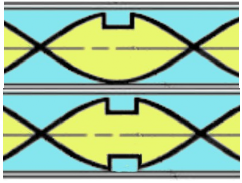
(a) Schematic diagram
(b) Tested types of twisted-tape
Figure 1. Details of the tested tube and twisted-tapes
Table 1. The dimensions of the test section
|
Parameter |
Symbol |
Dimensions |
|
Tube length (mm) |
L |
1000 mm |
|
Inner diameter (mm) |
Di |
24 mm |
|
Outer diameter (mm) |
Do |
28 mm |
|
Tube thickness (mm) |
t |
4 mm |
|
Tape thickness (mm) |
d |
2 mm |
|
Tape width (mm) |
w |
22 mm |
|
Tape pitch (mm) |
y |
108 mm |
|
Cut depth (mm) |
a |
3,5,7,9 mm |
|
Cut width (mm) |
b |
10 mm |
Tests were conducted on the various cutting ratios to see how they affected performance outcomes. One technique for determining the fluid mechanics flow process is computational fluid dynamics (CFD) modeling, which solves and analyzes problems involving fluid flows using numerical techniques and algorithms. A clear display of the tested model is provided in Table 1.
2.2 Governing equations
The equations to be resolve for the flow are the conservation of mass equation [17] momentum and:
Continuity equations [17]:
$\frac{\partial u}{\partial x}+\frac{\partial v}{\partial y}=0$ (1)
Momentum equations:
In x-direction:
$u \frac{\partial u}{\partial x}+v \frac{\partial u}{\partial y}+w \frac{\partial u}{\partial z}=-\frac{1}{\rho} \frac{\partial P}{\partial x}+\frac{\mu}{\rho}\left(\frac{\partial^2 u}{\partial x^2}+\frac{\partial^2 u}{\partial \ y^2}+\frac{\partial^2 u}{\partial z^2}\right)$ (2)
In y-direction:
$u \frac{\partial v}{\partial x}+v \frac{\partial v}{\partial y}+w \frac{\partial v}{\partial z}=-\frac{1}{\rho} \frac{\partial P}{\partial y}+\frac{\mu}{\rho}\left(\frac{\partial^2 v}{\partial x^2}+\frac{\partial^2 v}{\partial y^2}+\frac{\partial^2 v}{\partial z^2}\right)$ (3)
In z-direction:
$u \frac{\partial w}{\partial x}+v \frac{\partial w}{\partial y}+w \frac{\partial w}{\partial z}=-\frac{1}{\rho} \frac{\partial P}{\partial z}+\frac{\mu}{\rho}\left(\frac{\partial^2 w}{\partial x^2}+\frac{\partial^2 w}{\partial y^2}+\frac{\partial^2 w}{\partial z^2}\right)$ (4)
Energy equation [18]:
$u \frac{\partial T}{\partial x}+v \frac{\partial T}{\partial y}+w \frac{\partial T}{\partial z}=\alpha\left(\frac{\partial^2 T}{\partial x^2}+\frac{\partial^2 T}{\partial y^2}+\frac{\partial^2 T}{\partial z^2}\right)$ (5)
Among the most commonly utilized turbulence models is the (k-ε) model. Additionally, two transport equations are included in this model to illustrate the characteristics of turbulent flow. Kinetic energy is transmitted first, and turbulent dissipation.
|
σk |
σε |
C1ε |
C2ε |
|
1.00 |
1.30 |
1.44 |
1.92 |
The input is specified from:
$\mathrm{Q}=m^O \mathrm{C}_{\mathrm{p}}\left(T_o-T_i\right)$ (6)
$\bar{h}$ is evaluated from the following formula:
$\overline{\mathrm{h}}=\frac{Q}{A_s\left(T_w-T_b\right)}$ (7)
The wall temperature (Tw) [19] is found by:
$\mathrm{T}_{\mathrm{w}}=\frac{1}{n} \sum T_{w n}$ (8)
The bulk-temperature (Tb) [20] is found by:
$T_b=\frac{\int_0^{\mathrm{L}} \int_0^{\mathrm{H}} \int_0^W \rho\ c_p\ u T\ d x\ d y\ d z}{\int_0^{\mathrm{L}} \int_0^{\mathrm{H}} \int_0^W \rho\ u\ d x\ d y\ d z}$ (9)
(Nu) is estimated as:
$N u=\frac{\bar{h} \cdot D_h}{k}$ (10)
Friction factor found by Darcy Weisbach equations as [21]:
$\mathrm{f}=\frac{\Delta P . D_h}{\frac{1}{2} \rho u_{\text {avg } \cdot L}^2}$ (11)
The ratio of a raised surface's coefficient of the heat-transfer (h) to the coefficient of a smooth channel $\left(h_s\right)$ with no protrusion at equal pumping power is known as the thermal hydraulic.
Or it’s the ratio of (Nu / Nuo) the thermal enhancement ratio and (f / fo) is the friction factor ratio.
To indicted overall performance [22] is reached by:
$\eta=\frac{h}{h_s}\left(N u / N u_o\right) /\left(f / f_0\right)^{1 / 3}$ (12)
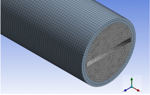
Figure 2. Mish generation
Table 2. Grid independency of the study
|
The case |
Number of Elements |
Nu |
f |
|
Plain tube |
5865445 |
39.654 |
0.114 |
|
6043222 |
41.455 |
0.133 |
|
|
6275433 |
43.231 |
0.146 |
|
|
6533844 |
44.344 |
0.153 |
|
|
Tube inserted with twisted tape single cut |
8402345 |
129.766 |
0.164 |
|
8437767 |
13.121 |
0.177 |
|
|
8500311 |
131.779 |
0.183 |
|
|
8524944 |
132.366 |
0.189 |
|
|
Tube inserted with twisted tape double cut |
8486634 |
172.642 |
0.093 |
|
8505433 |
175.887 |
0.113 |
|
|
8522755 |
177.441 |
0.219 |
|
|
8567902 |
177.534 |
0.223 |
2.3 Grid independency
Quad grids were used whenever feasible in the mesh creation process; as a result, the tube and the regions passing through the flow domain were covered with quad grids. To improve the mesh near the walls with higher temperature and velocity gradients, boundary layer meshes surrounding twisted tape and tube inner surfaces were employed. Curvature grids are employed for the remaining flow domain.
The resultant grid is seen clearly in Figure 2. The tests of grid dependence are run at Re = 5000 in order to determine the values of (Nu) and (f) as shown in Table 2.
The effectiveness of adding twist tape to a tube in terms of enhancing overall thermal performance as well as its impact on other flow characteristics like heat transfer (Nu) and ∆p was investigated through the use of numerical simulations using the ANSYS Fluent tool. Initially, two different cutting techniques were tested: single and double (upper and lower). Testing the cutting ratio's impact involved increasing it from 0.3 to 0.9 and varying the fluid flow velocity at which Reynolds ranged from 5000 to 25000.
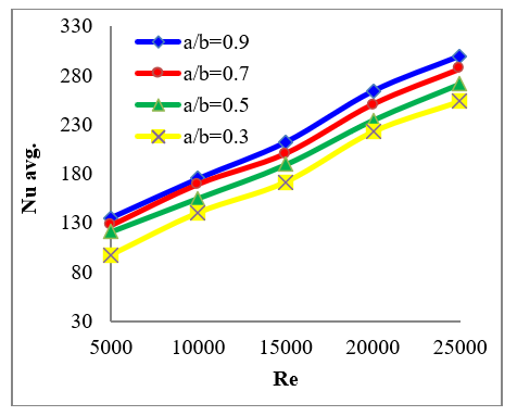
The fact that a larger flow disturbance is produced close to the tube walls by recirculation and rotational flow as the Re. number raises helps to explain the differences in Nusselt number (Nu). This indicates that there is a rise in the fluid mixing between the core and areas close to the surface due to powerful vortices. According to the outcomes, tubes fitted with double and single cut with larger cut ratios have considerably best thermal- performance than tubes with smaller cut ratios. as seen in Figures 3 and 4.
Figure 3. Variation in Nu with Re for tubes equipped with double-cut twisted-tapes
Figure 4. Variation in Nu with Re for tubes prepared with single-cut twisted-tapes
Conversely, the findings of the friction factor (f) demonstrated that, for all values of Re, the twisted tape with a double cut had the greatest values when compared to the single-cut instance. Where the increasing in (f) in double cut is about 18%. That’s up to the rising in pressure drop through the fluid flow. As displays in Figures 5 and 6.
Figure 5. Variation in f. with Re for tube equipped with the double-cut twisted-tape
Figure 6. Variation in f. with Re for tube equipped with the single-cut twisted-tape
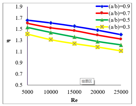
Figure 7. Variation in $\eta$ with the Re for tube equipped with double-cut twisted-tape
Figures 7 and 8 show how the cut-ratio, cutting technique, and Reynolds number affect the thermal-performance factor. It is evident that when Re rises, (η) falls. As the twisted tape's cut ratio increases, it is evident that the performance raised. That means that when using twisted tape with bigger cut ratios, thermal performance improves noticeably because of the raised vortex flow. The obtained data indicates that the double cut provides higher values of overall performance for all Re values when the two cutting methods (single-cut and double-cut) are compared.
The most noteworthy heat transfer (highest Nusselt number values) was selected for the two cases tried: tube prepared with single and double cutting twisted - tapes at cut ratio (a/b)=0.9. Figure 9 displays a comparison among the Nu. Values for the plain-tube, the tube with the twisted tape embedded, tube prepared with single-cut twisted. tape at cut ratio (a/b)=0.9 and tube with double-cut at (a/b)=0.9. The results show a clearly difference between the values. Where the case g of the double-cut gives most noteworthy values by a difference of 11% from the case of single-cut and 19% from the standard twisted - tape and 42% from the basic smooth tube.
Figure 8. Variation in $\eta$ with the Re for tube prepared with single-cut twisted-tape
Figure 9. Variation in Nu with Re for tubes equipped with double-cut twisted tapes
A numerical simulation was conducted to determine the validation between the results of the current research and two previous studies: Salam et al. [23] for several Reynolds values ranged between 10000 and 19000. The values of the friction factor were different in the three tested cases, Entrance effect could be the reason for this and the different in parameter (Figure 10).
Figure 10. Validation current study and previous studies, Salam and Gnielinski to compared the Nu
(a) at a distance 162 mm
(b) at a distance 500 mm
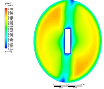
Figure 11. Velocity contour of double cut twisted tape at Re=5000, (a/b)=0.9
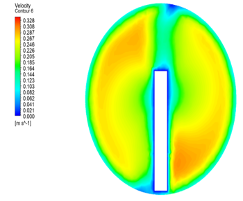
The numerical contours of velocity the twisted tape that was inserted in the tube produces swirl flows close to the core, which is clearly shown in Figures 11 and 12, and results in robust fluid mixing. Furthermore, these swirl flows increase the fins tape's influence and the flow length's effectiveness; as a result, this behavior is unquestionably enhanced and improved. the heat exchanger's overall thermal performance. For each case, two cross-sections are shown in the picture at a distance of 162 mm and 500 mm.
Figure 13 demonstrates that, compared to the single-cut type, the tube with the double-cut type has a larger contact surface range, a narrower thermal boundary, and an efficient swirl flow up to the temperature contours.
(a) at a distance 162 mm
(b) at a distance 500 mm
Figure 12. Velocity contour of single-cut twisted. tape at Re=5,000, (a/b)=0.9
(a) Temperature contour of the tube with twisted - tape (double cut)
(b) Temperature contour of the tube with twisted - tape (single cut)
Figure 13. Velocity contour of single-cut twisted - tape at Re=5,000, (a/b)=0.9
(a) at a distance 162 mm
(b) at a distance 500 mm
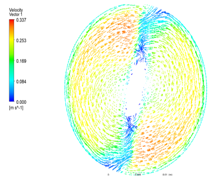
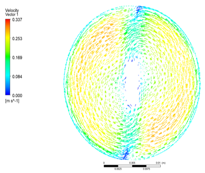
Figure 14. Velocity contour of single cut twisted tape at Re=5000, (a/b)=0.9
(a) at a distance 162 mm
(b) at a distance 500 mm
Figure 15. Velocity contour of single-cut twisted. Tape at Re=5,000, (a/b) =0.9
The case featuring a double-cut twist. More separation flow and stronger vortices forming upstream are provided by the tape, which improves the flow field's mixing of turbulence. In order to maximize heat transfer, this cutting technique forms complicated flows and increases turbulence. Figures 14 and 15 give an evidence image for the velocity vector of the two cases.
In the current work, a pipe fitted with twisted-tape is employed to report heat transfered and flow characterstices. The following succinctly summarizes the work's main conclusions:
➢ Twisted tape installed in the tube's core encourages swirl flow over the tube, while the surface equipped with twisted tape creates secondary flow and encourages turbulence close to the surfaces. When twisted-tape is used, thermal performance and heat transfer are improved over a tube without twisted tape.
➢ For the two studied scenarios (double and single cut), heat transfer increases as the cut ratio (a/b) increases. This is explained by the intense swirling that promotes the destruction of the thermal boundary along the tube surfaces.
➣ Re decreases lead to a rise in (η), which grows in proportion to the cutting ratio (a/b). The ratio of double cut type of 0.9 is employed to achieve the greatest thermal performance, which is 1.69 at Re=5000. In the applied of a single cut type, the lowest cut ratio (a/b) of 0.3 delivers smaller thermal performance; at Re=25000, it is found to be 0.96.
➣In terms of energy savings, using twisted - tapes is also more feasible at low Re(velocity) levels. Stated differently, the results obtained permit the building of a small heat exchanger requiring the least amount of pumping power. in addition to optimizing energy consumption in the engineering and thermal systems.
In order to improve heat transfer by mixing the fluid more, it may be conceivable to test the addition of coils, fins, and baffles, or to increase the number of slits in the twisted-tape in future studies.
|
A |
Area of cross - section (m2) |
|
Cp |
Specific heat of .water at constant pressure (J/kg.K) |
|
D |
Diameter of the pipe(m) |
|
f |
Friction factor (-) |
|
h |
Heat transfered coefficient (W/m2.K) |
|
k |
Thermal conductivity of water (W/m.K) |
|
L |
length of pipe (m). |
|
mo |
Mass flow rate of water (kg/s). |
|
Q |
Heat - transfer rate (W) |
|
q |
Heat flux. (W/m2) |
|
T |
Temperature (℃). |
|
u |
velocity of fluid |
|
Nu |
Nusselt number. |
|
P |
Pressure drop (N/m2). |
|
Re |
Reynolds number (-) |
|
y |
Tape pitch (m) |
|
w |
Tape width (m) |
|
Greek symbols |
|
|
δ |
Tape thickness (m) |
|
ρ |
Density of water (kg/m3) |
|
µ |
Viscosity of water (kg/m.s) |
|
η |
Overall performance (-) |
|
Subscripts |
|
|
b |
Bulk |
|
I |
Local value in Inlet |
|
o |
Outlet |
[1] Khargotra, R., Kumar, R., Nadda, R., Dhingra, S., Alam, T., Dobrota, D., Chicea, A.L., András, K., Singh, T. (2023). A review of different twisted tape configurations used in heat exchanger and their impact on thermal performance of the system. Heliyon, 9(6): e16390. https://doi.org/10.1016/j.heliyon.2023.e16390
[2] Hong Y.X., Du J., Wang S.F., (2017). Experimental heat transfer and flow characteristics in a spiral grooved tube with overlapped large/small twin twisted tapes. International Journal of Heat and Mass Transfer, 106: 1178-1190. https://doi.org/10.1016/j.ijheatmasstransfer.2016.10.098
[3] Chammam, W., Farooq, U., Sediqmal, M., Waqas, H., Yasmin, S., Zulfiqar, F., Liu, D., Khan, S.A. (2023). Estimation of heat transfer coefficient and friction factor with showering of aluminum nitride and alumina water based hybrid nanofluid in a tube with twisted tape insert. Scientific Reports, 13: 23071. https://doi.org/10.1038/s41598-023-49142-w
[4] Nashee, S.R. (2023). Numerical study for fluid flow and heat transfer characteristics in a corrugating channel. International Journal of Heat & Technology, 41(2): 392-398. https://doi.org/10.18280/ijht.410213
[5] Tan, X.H., Zhu, D.S., Zhou, G.Y., Yang, L. (2013). 3D numerical simulation on the shell side heat transfer and pressure drop performances of twisted oval tube heat exchanger. International Journal of Heat and Mass Transfer, 65: 244-253. https://doi.org/10.1016/j.ijheatmasstransfer.2013.06.011
[6] Nashee, S.R., Ibrahim, Z.A., Kamil, D. (2024). Numerical investigation of flow in vertical rectangular channels equipped with three different obstacles shape. AIP Conference Proceeding, 3122: 100002. https://doi.org/10.1063/5.0216016
[7] Thianpong, C., Eiamsa-ard, P., Eiamsa-ard, S. (2012). Heat transfer and thermal performance characteristics of heat exchanger tube fitted with perforated twisted-tapes. Heat and Mass Transfer, 48: 881-892. https://doi.org/10.1007/s00231-011-0943-0
[8] Kumar, R., Mohammadpoura, A., Jamali-Asthiania, M. (2009). Effect of twisted tape insert on heat transfer and pressure drop in horizontal evaporators for the flow of R-134a. International Journal of Refrigeration, 32(5): 922-930. https://doi.org/10.1016/j.ijrefrig.2008.11.004
[9] Man, C.Z., Lv, X.G., Hu, J.W., Sun, P.Y., Tang, Y.B. (2017). Experimental study on effect of heat transfer enhancement for single-phase forced convective flow with twisted tape inserts. International Journal of Heat and Mass Transfer, 106: 877-883. https://doi.org/10.1016/j.ijheatmasstransfer.2016.10.026
[10] Prasad P.V.D., Gupta, A.V.S.S.K.S. (2016). Experimental investigation on enhancement of heat transfer using Al2O3/water nanofluid in a u-tube with twisted tape inserts. International Communication of Heat and Mass Transfer, 75: 154-161. https://doi.org/10.1016/j.icheatmasstransfer.2016.03.019
[11] Eiamsa-ard, S., Promthaisong, P., Thianpong, C., Pimsarn, M., Chuwattanakul, V. (2016). Influence of three-start spirally twisted tube combined with triple-channel twisted tape insert on heat transfer enhancement. Chemical Engineering and Processing: Process Intensification, 102: 117-129. https://doi.org/10.1016/j.cep.2016.01.012
[12] Hong, Y.X., Deng, X.H., Zhang, L.S. (2012). 3D numerical study on compound heat transfer enhancement of converging-diverging tubes equipped with twin twisted tapes. Chinese Journal of Chemical Engineering, 20(3): 589-601. https://doi.org/10.1016/S1004-9541(11)60223-1
[13] Kumbhar, D.G., Sane, N.K. (2015). Exploring heat transfer and friction factor performance of a dimpled tube occupied with regularly spaced twisted tape inserts. Procedia Engineering, 127: 1142-1149. https://doi.org/10.1016/J.PROENG.2015.11.480
[14] Hasanpour, A., Farhadi, M., Sedighi, K. (2016). Experimental heat transfer and pressure drop study on typical, perforated, V-cut and 2 U-cut twisted tapes in a helically corrugated heat exchanger. International Communications in Heat and Mass Transfer, 71: 126-136. https://doi.org/10.1016/j.icheatmasstransfer.2015.12.032
[15] Sivashanmugam, P., Suresh, S. (2006). Experimental studies on heat transfer and friction factor characteristics of laminar flow through a circular tube fitted with helical screw-tape inserts. Applied Thermal Engineering, 26(16): 1990-1997. https://doi.org/10.1016/j.applthermaleng.2006.01.008
[16] Sivashanmugam, P., Suresh, S. (2007). Experimental studies on heat transfer and friction factor characteristics of turbulent flow through a circular tube fitted with helical screw-tape inserts. Applied Thermal Engineering, 27(8-9): 1311-1319. https://doi.org/10.1016/j.applthermaleng.2006.10.035
[17] Murugesan, P., Mayilsamy, K., Suresh, S., Srinivasan, P.S.S. (2011). Heat transfer and pressure drop characteristics in a circular tube fitted with and without V-cut twisted tape insert. International Communications in Heat and Mass Transfer, 38(3): 329-334. https://doi.org/10.1016/j.icheatmasstransfer.2010.11.010
[18] Shakir, R. (2023). Prediction study of the boiling flow of heat transfer in an array of in-line micro-pin-fins heat sink. American Institute of Physics Conference Series, 2845(1): 060003. https://doi.org/ 10.1063/5.0157017
[19] Nashee, S.R. (2024). Enhancement of heat transfer in nanofluid flow through elbows with varied cross-sections: A computational study. International Journal of Heat and Technology, 42(1): 311-319. https://doi.org/10.18280/ijht.420133
[20] Fagr, M.H., Rishak, Q.A., Mushatet, K.S. (2020). Performance evaluation of the characteristics of flow and heat transfer in a tube equipped with twisted tapes of new configurations. International Journal of Thermal Sciences, 153: 106323. https://doi.org/10.1016/j.ijthermalsci.2020.106323
[21] Nashee, S.R., Hmood, H.M. (2023). Numerical study of heat transfer and fluid flow over circular cylinders in 2D cross flow. Journal of Advanced Research in Applied Sciences and Engineering Technology, 30(2): 216-224. https://doi.org/10.37934/araset.30.2.216224
[22] Hamood, H.M., Mansour, M.M., Lafta, A.M., Nashee, S.R. (2024). Numerical investigation to study the effect of three height of triangular obstacles on heat transfer of nanofluids in a microchannel. International Review of Mechanical Engineering (IREME), 17(11). https://doi.org/10.15866/ireme.v17i11.23627
[23] Salam, B., Biswas, S., Saha, S., Bhuiya, M.M.K. (2013). Heat transfer enhancement in a tube using rectangular-cut twisted tape insert. Procedia Engineering, 56: 96-103. https://doi.org/10.1016/j.proeng.2013.03.094