Peng Li![]() | Shunheng Hua*
| Shunheng Hua*![]() | Yue Yu
| Yue Yu![]() | Xinru Tong
| Xinru Tong![]() | Yang Xu
| Yang Xu![]() | Minyi Zhao
| Minyi Zhao![]() | Peiwen Xu
| Peiwen Xu![]()
© 2024 The authors. This article is published by IIETA and is licensed under the CC BY 4.0 license (http://creativecommons.org/licenses/by/4.0/).
OPEN ACCESS
This investigation, utilizing the Fire Dynamics Simulator (FDS), explored the impact of dual fire source scenarios within tunnels, particularly focusing on temperature distribution and natural smoke exhaust in tunnels equipped with shaft ventilation. The study compared these scenarios against those involving a single fire source by varying the spacing between fire sources and adjusting longitudinal wind speeds. It was found that the speed of smoke propagation accelerated as the distance between fire sources increased, under a constant power of the individual fire sources. The temperature profiles of the tunnel ceiling under various scenarios exhibited considerable consistency. At lower longitudinal wind speeds, the temperature upstream of the fire source was higher compared to the downstream area, with the minimum temperature recorded at the shaft entrance. Notably, the critical wind speed, defined for a single fire source scenario with power equivalent to the combined power of two closely spaced fire sources, decreased with increasing distance between the fire sources, revealing a finite limit. In the shaft, a pattern was observed where the smoke temperature, gas mass flow, and carbon monoxide concentration initially increased and then decreased with a rise in longitudinal wind speed, reaching optimal efficiency in smoke exhaust at a wind speed of 2m/s. The complexities inherent in dual fire source scenarios were more pronounced compared to single fire source scenarios, presenting increased risks to safety and health during a fire. This study underscores the need for strategic planning in tunnel design, particularly in accommodating ventilation systems that can effectively respond to varying fire source scenarios.
dual fire sources, fire source spacing, longitudinal wind speed, shaft ventilation, tunnel fire simulation
Recent developments in China's road infrastructure have established the nation as a global leader in terms of the quantity, scale, and growth rate of road tunnels. The unique characteristics of tunnels, being narrow, elongated, and enclosed with limited access points, pose significant risks in the event of a fire. Toxic smoke and intense heat generated during such incidents can rapidly create life-threatening conditions [1, 2]. Incidents in tunnels are predominantly due to vehicular collisions or structural interactions rather than spontaneous vehicle combustion, often leading to fires at multiple locations. These multi-source fires result in altered smoke and temperature propagation patterns within the tunnel compared to single-source fires [3, 4]. The complexity introduced by dual fire source scenarios necessitates focused research on smoke control strategies in these environments.
The design of natural smoke exhaust systems in tunnels, especially those incorporating shaft ventilation, has received considerable attention for its cost-effectiveness and operational efficiency. This approach is now a common feature in many urban and long-distance road tunnels. Zhao et al. [5] explored the characteristics of buoyancy-driven smoke flow in shaft tunnels using scaled models. Their research revealed that increasing the number of shafts, along with their height and cross-sectional area, significantly enhances smoke exhaust efficiency and facilitates smoke stratification within these shafts. Xu et al. [6], employing theoretical analysis and Large Eddy Simulation (LES), delved into the problem of smoke layer blocking. Their innovative design of smoke reservoirs beneath the shafts effectively increased the thickness of the smoke layer, thereby preventing blockage and improving exhaust efficiency. Further, Ji et al. [7] utilized LES to assess the influence of shaft height on natural smoke exhaust in road tunnel shafts, identifying an optimal shaft height for maximal exhaust efficiency. Beyond this optimal height, a decrease in efficiency was observed, with the critical blocking height emerging as the most effective value for smoke exhaust. Wan et al. [8] conducted numerical simulations to investigate the impact of tunnel slope on various aspects, including the temperature distribution in shafts and tunnels, the length of smoke back layer, and tunnel inflow velocity. They found that an increase in tunnel slope could mitigate the blockage effect and lower temperatures in specific shaft areas. The length of the smoke back layer was reduced with an increasing slope, irrespective of the fire source's power and location. Additionally, tunnel inflow velocity was found to increase with both the tunnel's slope and its Heat Release Rate (HHR). Fan et al. [9], through LES, examined the effects of shaft arrangement on the natural ventilation performance in tunnel fires. Their findings indicated that blockage and boundary layer separation significantly influence natural ventilation, with the total mass of smoke exhausted from the shafts augmenting proportionally with the number of shafts.
The integration of shaft exhaust and longitudinal ventilation in tunnel smoke extraction schemes has been recognized for its enhanced efficiency in controlling fire-induced smoke. The performance of shaft smoke exhaust is intricately linked to longitudinal wind, with suboptimal longitudinal ventilation potentially impeding effective smoke discharge. Numerical simulations conducted by Wang et al. [10] under varied environmental pressures, fire source power, and longitudinal wind speeds revealed that decreased environmental pressure accentuated the differences in carbon monoxide concentration and smoke temperature both longitudinally and vertically. It was observed that longitudinal ventilation augmented the performance of shaft smoke exhaust, although this effect diminished with escalating wind speed. Research by Zhong et al. [11], employing Large Eddy Simulation, delved into the impact of longitudinal wind on natural ventilation in highway tunnel fires. Findings suggested that smaller longitudinal winds could lead to blockages, diminishing the efficacy of shaft smoke exhaust. Notably, the efficiency of shaft smoke exhaust did not increase proportionally with the rise in longitudinal wind speed. Excessively strong longitudinal winds were found to disrupt the boundary layer, thus reducing shaft exhaust capability. The studies identified an optimal longitudinal wind speed conducive to achieving peak smoke exhaust results.
Gao et al. [12] developed a scaled tunnel model to examine tunnel fire smoke flow and temperature distribution characteristics, especially under the combined effects of longitudinal ventilation and natural shaft exhaust. In scenarios devoid of longitudinal ventilation, a rapid decrease in smoke temperature near shafts was observed, alongside an asymmetric distribution of smoke temperatures upstream and downstream of the fire source. Moreover, increasing wind speed resulted in a reduction in the length of smoke backflow and temperature distribution, while the maximum temperature drift length showed an increasing trend. Cong et al. [13] utilized Large Eddy Simulation to analyze the ventilation properties of shafts in tunnel fires, investigating smoke flow effects under varying longitudinal winds and different heat release rates. It was concluded that larger fires under consistent longitudinal winds led to enhanced smoke exhaust efficiency, with different fire scenarios necessitating distinct ventilation speeds.
Presently, the majority of research has focused on single fire source combustion in shaft ventilated tunnels and dual fire source tunnel fires lacking shaft ventilation. However, there is a dearth of research concerning the effects of fires in dual fire source tunnels with shaft ventilation on the tunnels and shafts themselves. To address this gap, this study will employ the FDS software for an in-depth investigation.
2.1 Model establishment
FDS, developed by the United States' National Institute of Standards and Technology (NIST), serves as a computational tool for simulating fire scenarios [14]. Its widespread application by researchers in simulating real-life fire incidents [15-17] has been noted for producing results that closely mirror the actual dynamics of smoke movement in fire events. For the purpose of this study, the PyroSim software was utilized to construct a model of a highway tunnel incorporating a shaft. This tunnel model is characterized by dimensions of 120 meters in length, 10 meters in width, and 5 meters in height. The shaft, designed with a cross-sectional area measuring 2 meters by 2 meters and a height of 5 meters, is strategically located directly above the tunnel's central longitudinal axis, 50 meters from the right entrance of the tunnel. The fire source placement within the tunnel model is specified at 70 meters from the right entrance and 20 meters from the shaft entrance, aligned along the tunnel's longitudinal centerline. In this context, the distance 'D' between dual fire sources is defined as the span from the right extremity of the first fire source to the left boundary of the subsequent fire source, maintaining a constant relative position of the latter fire source to the shaft. Figure 1 presents a schematic representation of the tunnel's geometric model.
Figure 1. Geometric model of the tunnel
2.2 Computational conditions and measurement point arrangement
This study's tunnel model, reflective of an actual highway tunnel project, predominantly accommodates cars, small trucks, and buses. Adhering to the National Fire Protection Association (NFPA) 502 guidelines for highway tunnel fire scales [18], fire source powers were designated as 5 MW, 10 MW, and 20 MW for cars, small trucks, and buses, respectively. In scenarios involving dual fire sources, each source was assigned a power of 10 MW, simulating challenging conditions like the burning of small trucks or buses in highway tunnels. The fire sources were fueled by n-heptane, characterized by a carbon monoxide yield rate of 0.006 and a soot mass yield rate of 0.015. The tunnel's right side and the shaft opening were configured as “open”, establishing a connection with the external environment, while the left side opening was set as “supply”, indicative of the presence of longitudinal wind ranging from 0m/s to 3m/s. The tunnel's initial temperature and atmospheric pressure were set at 20℃ and the standard 101.325 kPa, respectively, with “concrete” as the material for both the tunnel and shaft, mirroring real-world constructions.
Temperature slices were methodically arranged along the tunnel's longitudinal centerline. This arrangement included 120 thermocouples and carbon monoxide concentration measurement points placed every meter along the length, 0.1 meters below the tunnel's ceiling. On a plane at Z=2m, temperature and carbon monoxide measurement points were uniformly distributed at 1-meter intervals along the centerline. To monitor temperature and carbon monoxide concentration changes within the tunnel and shaft, slices were positioned on the Y=5m plane. Moreover, five carbon monoxide concentration measurement points, situated 0.1 meters from the shaft's top opening for averaging purposes, along with gas mass flow points, were established to assess the shaft's smoke exhaust performance. Recognizing the impracticality of a fire source achieving its maximum heat release rate instantly in actual incidents, the study treated tunnel combustion as unsteady. The unsteady heat release rate's growth function predominantly utilized a t² growth function, expressed as:
Table 1. Fire growth coefficient
|
Fire Categories |
Typical Combustible Materials |
Fire growth Coefficient (kw/s²) |
|
Slow fire |
Hardwood furniture |
0.0029 |
|
Medium fire |
Cotton and polyester mattresses |
0.0117 |
|
Fast fire |
Wooden pallets and foam plastics |
0.0469 |
|
Ultra-fast fire |
Pool fires and lightweight flammable decorative furniture |
0.1876 |
$Q=\alpha t^2$ (1)
where, Q denotes the fire power (kW); $\alpha$ symbolizes the combustion growth coefficient (kW/s2), with reference values [19] presented in Table 1; and t represents the combustion time (s). The fire source was modeled as an ultra-fast unsteady fire. For a fire source power of 10 MW, the calculated time t approximated 231s, enabling smoke flow to reach a stable state. Similarly, for a 20 MW power, t was around 327s, thus the simulation runtime was set to 600s to ensure smoke flow stability.
2.3 Grid independence analysis
In the realm of FDS fire simulations, the selection of an appropriate grid size is pivotal for ensuring the precision of results. A smaller grid size, while enhancing experimental accuracy, imposes substantial demands on computational resources and escalates the complexity of the experiment. In contrast, opting for a larger grid size might compromise both the accuracy and scientific integrity of the results. Drawing from independent grid size experiments conducted by McGrattan et al. [20], the ratio between the fire characteristic diameter D* and the tunnel grid size dx is typically within the range of 4 to 16. The formula for calculating D* is as follows:
$D^*=\left(\frac{Q}{\rho_0 c_\rho T_0 g^{1 / 2}}\right)^{2 / 5}$ (2)
where, Q denotes the heat release rate of the fire source (kW); r0 is the air density (kg/m³), with a value of 1.205kg/m3; cp represents the specific heat capacity of air (kJ/(kg·K)), set at 1.003kJ/(kg·K); T0 is the ambient temperature, measured in Kelvin, and assigned a value of 293K(20℃); g stands for the acceleration due to gravity (m/s²), which is 9.81m/s².
For a fire source with a power of 10 MW in this study, the grid size was calculated to be within the range of 0.150m to 0.599m, based on the fire characteristic diameter formula and the grid size ratio. Simulations were executed with grid sizes of 0.167m, 0.2m, 0.333m, and 0.5m to determine an optimal size. Figure 2 depicts the temporal temperature variation at the tunnel roof directly above the fire source. Given the unsteady nature of the fire source in the experiment, significant temperature fluctuations were observed. It was noted that the temperature range for a grid size of 0.5m was substantially lower than that of the other sizes. As the grid size decreased, the differences in temperature range became negligible. Consequently, considering the balance between computational efficiency and experimental time, a grid size of 0.333m was selected for the simulations.
Figure 2. Roof temperature variations in the tunnel under different grid sizes
2.4 Scheme design and simulation of working conditions
For the experimental simulations conducted in this study, scenarios involving dual fire sources were established, with each source having a power of 10 MW. Comparative analyses were also carried out with a single fire source scenario, where the fire source was assigned a power of 20 MW. Figures 3-5 illustrate the variations in smoke dispersion within a shaft ventilated tunnel under different longitudinal wind speeds for a single fire source of 20 MW.
Figure 3. Longitudinal wind speed at 0m/s
It was observed that in the absence of longitudinal ventilation, smoke initially reached the tunnel's ceiling and subsequently dispersed in both directions. By 200s, the smoke had extended to both ends of the tunnel, starting to disperse downwards, with a notably thinner smoke layer beneath the shaft compared to the sides. At 400s, as the fire source attained its maximum heat release rate and stabilized, a considerable amount of smoke accumulated within the tunnel, exhibiting clear stratification with similar distribution patterns both upstream and downstream.
Figure 4. Longitudinal wind speed at 1m/s
Figure 5. Longitudinal wind speed at 2.8m/s
With a longitudinal wind speed of 1m/s, the smoke dispersion was slower compared to the scenario without longitudinal wind, and backflow of smoke was still evident. By 200s, the smoke had predominantly dispersed to the left end of the tunnel. Due to the influence of the longitudinal wind, the thickness of the smoke layer upstream of the fire source was significantly greater than downstream. At 400s, heavy smoke accumulation on the tunnel's left side and the chimney effect of the shaft on the right led to asymmetric smoke distribution and thinner smoke layers near the ventilation shaft. At a longitudinal wind speed of 2.8m/s, no smoke propagation was observed upstream of the fire source at various intervals, indicating a backflow distance of zero. Thus, the critical wind speed for a single fire source scenario with a power of 20 MW was determined to be 2.8m/s.
Previous studies [21-23] have demonstrated that as the distance between two fire sources increases to a certain threshold, the critical wind speed converges to a limit value. At this juncture, the critical wind speed is equivalent to that necessary for a single fire source. When the distance between two fire sources is zero, they effectively merge into a single source, and the critical wind speed corresponds to the combined power of both sources. Consequently, in the dual fire source scenarios of this study, distances between fire sources were set at 3m, 6m, and 9m. Simulations were then performed combining these distances with varying longitudinal wind speeds and were compared with a single fire source scenario of 20 MW, as detailed in Table 2.
Table 2. Settings for simulated working conditions
|
Fire Source Types |
Fire Source Power (MW) |
Fire Source Distance (m) |
Longitudinal Wind Speed |
|
Single fire source |
20 |
0 |
0m/s~3m/s |
|
Dual fire sources |
10/10 |
3 |
|
|
Dual fire sources |
10/10 |
6 |
|
|
Dual fire sources |
10/10 |
9 |
3.1 Longitudinal wind speed at 0m/s
In the event of a tunnel fire, smoke generated forms a plume rising freely to the ceiling, subsequently engaging in longitudinal, one-dimensional horizontal movement along the roof. This stage, characterized by the horizontal motion of smoke, marks the longest phase of fire spread and is critical for smoke control and evacuation efforts. Figure 6 illustrates the smoke dispersion at 60s post-fire outbreak under varying distances between dual 10 MW fire sources and a single 20 MW source.
It was observed that, at the same time interval, the smoke dispersion distance increased with the distance between fire sources, consequently reducing the time taken for smoke to reach the tunnel's left end. In scenarios involving dual fire sources, the length of smoke dispersion was notably longer than that in a single fire source scenario. As the distance between the dual fire sources widened, the extent of smoke dispersion correspondingly expanded. From the perspective of the right side of the fire source, the length of smoke dispersion in dual fire source scenarios consistently exceeded that in the single fire source scenario, indicating a higher smoke concentration produced by dual sources despite the single source's higher power.
Figure 6. Smoke dispersion in various fire scenarios
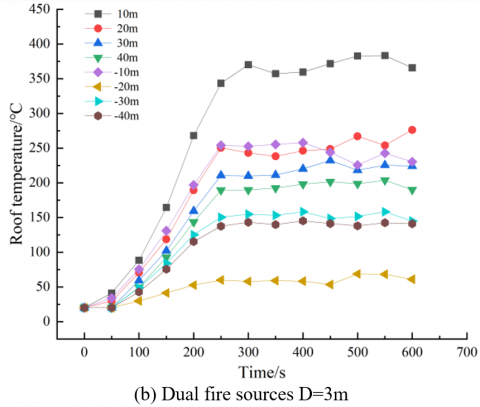
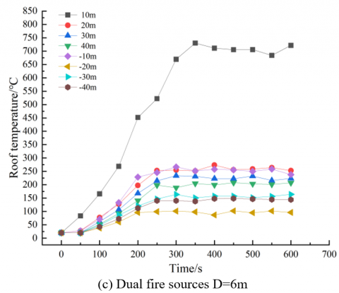
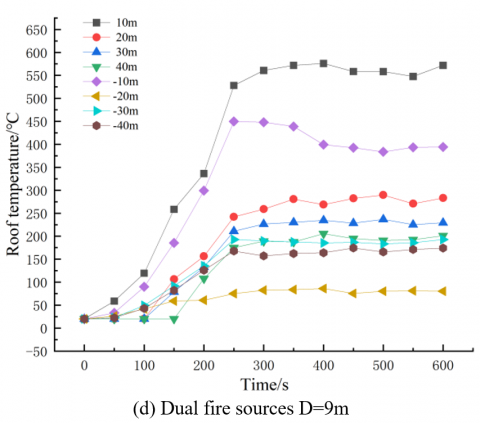
Post-fire, significant smoke accumulation occurs above the tunnel roof due to thermal buoyancy. Consequently, the roof temperature serves as an effective indicator of smoke dispersion within the tunnel. Figure 7 presents the temporal changes in roof temperature under various fire scenarios at distances of 10m, 20m, 30m, and 40m upstream and downstream from the fire source. The term "-10m" refers to the downstream area 10m from the fire source. Temperature characteristic curves across different scenarios exhibited general consistency, with higher roof temperatures and increased heat radiation closer to the fire source. Upon the fire source reaching its maximum heat release rate within 200~300s, the roof temperature typically peaked and stabilized. The introduction of shaft ventilation in the downstream area influenced smoke temperatures; when smoke reached the shaft entrance, the shaft's chimney effect markedly reduced smoke temperature. The "-20m" position, aligning with the center of the shaft entrance, recorded temperatures considerably lower than surrounding smoke temperatures, approximately between 20℃ and 50℃. Downstream temperatures were lower than upstream. At 10m upstream from the fire source, the dual fire sources at a 3m distance, predominantly influenced by the first fire source, demonstrated a roof temperature higher than in a single fire source scenario, attributable to the single source's double power. With dual fire sources at a 6m distance, the roof temperature directly above the first fire source reached around 725℃, significantly surpassing other scenarios. When the fire sources were 9m apart, the position's exposure to both fire sources due to flame merging led to higher roof temperatures than when D=3m.
Figure 7. Roof temperature changes under different working conditions
3.2 Longitudinal wind speed at 1m/s
Figure 8 exhibits the smoke dispersion in various scenarios 120s following a fire outbreak under a longitudinal wind speed of 1m/s. It was noted that the smoke, upon reaching the tunnel roof, gradually dispersed towards the left under the longitudinal wind's influence. The rate of smoke dispersion in dual fire source scenarios consistently surpassed that in the single fire source scenario. The longitudinal wind, flowing from upstream to downstream, significantly accelerated the smoke dispersion on the right side of the fire source, reaching the tunnel's right exit within 120s. In contrast to the no-wind condition, the initial smoke dispersion upstream in the early stages of the fire was slow, and smoke accumulation was observed downstream of the second fire source in dual fire source scenarios.
Figure 8. Smoke dispersion in different fire scenarios
This phenomenon could be attributed to the dual influence of longitudinal wind and downstream shaft ventilation: the wind pushed the smoke downstream, while the shaft's chimney effect slowed the dispersion, leading to smoke accumulation in this area. As the fire progressed and more smoke was produced, the wind speed proved inadequate in preventing smoke from eventually enveloping the entire upstream region of the fire source. However, the downstream area experienced substantially less smoke dispersion, benefiting from the shaft's ventilation.
With a longitudinal wind speed of 1m/s, the initial phase of the fire indirectly affected smoke propagation and, consequently, the roof smoke temperature in various scenarios. Figure 9 depicts the temperature changes at the roof, both upstream and downstream, under different fire scenarios with a 1m/s longitudinal wind. Echoing the no-longitudinal-ventilation scenarios, temperatures in both single and dual fire source scenarios rapidly escalated over time, stabilizing after reaching a certain level. Temperatures near the shaft entrance were notably lower than other roof locations, with temperature ranges in different scenarios generally falling between 50~100℃. Differently, the roof temperature upstream initially exhibited minimal change due to the longitudinal wind's effect, starting to climb after approximately 100s. The wind-induced tilt of flames downstream facilitated some smoke dispersion in that direction. As a result, the roof temperature 10m downstream exceeded that of 10m upstream, with the highest temperatures observed (except in the dual fire sources with a 9m distance scenario). This observation aligns with the earlier discussion on smoke accumulation downstream of the second fire source. In the single fire source scenario, the temperature 10m downstream of the roof was higher than in the dual fire source scenarios, correlating with greater power leading to increased heat radiation. In the dual fire source scenario with a 6m distance, the roof temperature 10m upstream, positioned directly above the first fire source, showed minimal difference compared to 10m downstream due to the longitudinal wind's influence, causing flame tilt and slower smoke dispersion. This factor contributed to the highest temperatures at the roof 10m upstream in the 9m distance scenario, where the longitudinal wind's effect on flame tilt elevated temperatures above other locations.
Figure 9. Roof temperature changes in different working conditions
3.3 Critical wind speed
Critical wind speeds for dual fire sources at varying distances were deduced through FDS simulations, following the methodology outlined for single fire source critical wind speed determination. Figure 10 illustrates the scenario at 360s into the fire, where each fire source has attained its maximum heat release rate, and no smoke dispersion upstream is evident due to the longitudinal wind's influence. It was discerned that at a zero-meter distance between dual fire sources, the critical wind speed is recorded at 2.8m/s, aligning with the critical wind speed for a single 20 MW fire source. When the inter-fire source distance is extended to 3m, the critical wind speed registers at 2.7m/s; at a 6m interval, it is noted as 2.6m/s; and at a 9m gap, it decreases to 2.5m/s. This trend underscores a continuous reduction in critical wind speed as the separation between dual fire sources increases. Upon reaching a certain separation, the critical wind speed approaches a stable value, rendering the fire scenario comparable to a single fire source comprising two similar sources. Conversely, at zero separation, the critical wind speed corresponds to that of a single fire source with a total power summing the dual sources, corroborating prior studies.
Figure 10. Critical wind speeds at varied dual fire source distances
Figure 11. Roof temperature changes in the downstream tunnel under different working conditions
In scenarios achieving the critical wind speed, the smoke backflow length is zero, signifying no smoke propagation upstream and the maintenance of initial ambient temperature (20℃) in the upstream tunnel. Figure 11 demonstrates the downstream roof temperature variation over time in different scenarios at critical wind speed. Upon reaching critical wind speed, irrespective of the dual fire sources' separation distances, the longitudinal wind induces downstream smoke dispersion in all scenarios, resulting in analogous downstream roof temperature shifts. Observations reveal that for dual 10 MW fire sources (unsteady fire), approximately 230s post-fire outbreak, the fire source's heat release rate peaks, followed by temperature saturation and gradual stabilization. In contrast, a single 20 MW fire source (unsteady fire) reaches its maximum heat release rate around 325s post-fire, emitting higher heat radiation than in dual fire source scenarios. Ultimately, the initial phase of any fire, whether involving a single or multiple sources, is critical for evacuation, with adequate longitudinal tunnel ventilation facilitating personnel evacuation and escape.
4.1 Analysis of shaft temperature variations
In the context of this study, the establishment of shafts above the tunnel exploits the chimney effect, arising from the density differential between internal and external environments. This phenomenon facilitates the outward flow of high-temperature smoke from the tunnel through the shaft, utilizing the thermal pressure effect. Not only does this process maintain smoke stratification, but it also efficiently expels a portion of the smoke generated during a fire incident. Moreover, it substantially reduces the temperature at the shaft's entrance, thereby aiding in the evacuation process and enabling swift escape from hazardous areas. Figure 12 depicts temperature variations within the shaft under different wind speeds, 360s into the fire (a state of stability with parameters such as thermal radiation and heat release rate being relatively stable). In dual fire source scenarios, D=6m is taken as an example, since the cloud diagram captures the tunnel length between 65~80m, precisely downstream of the fire source. Analysis from the previous section suggests that temperature curves beyond 10m downstream of the roof in different scenarios with varying distances and wind speeds in dual fire source cases are essentially similar.
From Figures 12(a) and (b), it is evident that during natural ventilation in the tunnel, the temperature inside the shaft under both scenarios does not differ significantly, remaining around 100℃, with minimal thermal stratification inside the tunnel. A low-temperature zone is observed at the shaft entrance, and the temperature below is almost the same as the ambient, due to the ingress of cold air from below the tunnel. Figures 12(c) and (d) indicate that at a longitudinal wind speed of 1m/s, the temperature inside the shaft is higher than in scenarios without longitudinal wind. The chimney effect of the shaft is relatively stronger here, with smoke primarily being exhausted through the shaft. Influenced by the longitudinal wind, a low-temperature zone still exists below the shaft on the side. The higher temperature below the shaft compared to the no-wind scenario could be due to smoke partially dispersing downstream of the fire source under the influence of the longitudinal wind. When the smoke reaches the shaft entrance, the strong vertical inertial force created by the chimney effect surpasses the horizontal inertial force of the smoke, causing partial smoke and cold air to be directly drawn into the shaft, resulting in a breakthrough phenomenon. The temperature inside the shaft in dual fire source scenarios is higher than in single fire source scenarios, correlating with the analyzed smoke dispersion, as the influence of longitudinal wind and shaft ventilation causes smoke accumulation at the downstream shaft entrance, increasing shaft exhaust and elevating shaft temperature. When longitudinal wind speed increases, the horizontal inertial force of the smoke inside the tunnel also increases, weakening the chimney effect and making the breakthrough phenomenon less likely.
Figure 12. Temperature distribution cloud diagram of shaft and downstream tunnel under different longitudinal winds
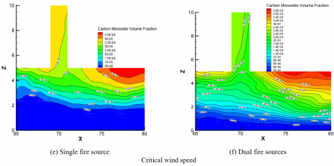
Figures 12(e) and (f) show the temperature distribution in the shaft and tunnel at critical wind speed, with no low-temperature zone at the shaft entrance and distinct smoke stratification inside the tunnel. In dual fire source scenarios, the smoke layer thickness is around 4.5m, greater than in single fire source scenarios. The temperature inside the shaft in single fire source scenarios is around 200℃, 50℃ higher than in dual fire source scenarios. Due to the higher wind speed, the fire smoke disperses entirely downstream, and the single fire source scenario, with greater power, releases more heat radiation than the dual fire source scenarios. At critical wind speed, the smoke exhaust efficiency in the single fire source scenario is better than in dual fire source scenarios, leading to a higher temperature and thinner smoke layer inside the shaft in the former.
4.2 Shaft gas mass flow and carbon monoxide concentration analysis
Figure 13 presents the variations in gas mass flow expelled from the shaft under different fire scenarios and longitudinal wind speeds. It was observed that the mass flow of gas discharged from the shaft exhibited an initial increase with wind speed, followed by a subsequent decrease. In dual fire source scenarios, the trend of gas mass flow remained largely consistent across different conditions, surpassing that of single fire source scenarios at equivalent wind speeds. From a longitudinal wind of 0m/s to 0.5m/s, there was a rapid increase in gas mass flow, which then plateaued with further increases in wind speed. The disruption of smoke stratification by longitudinal ventilation enhanced the smoke’s ability to entrain surrounding air, thereby escalating the mass flow. The peak of gas mass flow inside the shaft was reached at a wind speed of 2m/s, beyond which it demonstrated a declining trend. This finding underscores that higher wind speeds do not necessarily improve the shaft's smoke exhaust efficiency, and optimal exhaust efficiency is not guaranteed at critical wind speed. An ideal wind speed is necessary for maximal smoke exhaust efficiency in the shaft, aligning with findings from previous research [24, 25]. When the longitudinal wind speed surpassed the critical value, gas mass flow across all scenarios tended to converge due to the increased horizontal inertial force of the smoke, which diminished the chimney effect and reduced the smoke’s entrainment into the shaft.
Figure 13. Variation in gas mass flow under different longitudinal winds
Figure 14 illustrates the carbon monoxide concentration within the shaft and downstream tunnel at various longitudinal wind speeds. Upon the occurrence of a tunnel fire, combustion from vehicles produces copious smoke and toxic gases, which disperse and diminish visibility over time, complicating evacuation efforts. Individuals trapped within the fire zone are continually exposed to toxic gases, including carbon monoxide, carbon dioxide, hydrogen chloride, and hydrogen cyanide, among others. Carbon monoxide and carbon dioxide are notably responsible for causing unconsciousness or death [26]. Study [27] indicate that the maximum tolerable carbon monoxide concentration for adults is 50ppm (5×10⁻⁵mol/mol), with prolonged exposure at this level causing symptoms such as dizziness and nausea, and higher concentrations posing lethal risks.
The figure shows the carbon monoxide concentration 360s post-fire outbreak in both fire source scenarios, at which point the fire sources have reached and stabilized at their peak heat release rates. Generally, the concentration of carbon monoxide inside the shaft initially increased and then decreased with rising longitudinal wind, mirroring the pattern observed in gas mass flow. In the absence of longitudinal wind, the concentration of carbon monoxide below the shaft entrance was lower than that at the sides, indicating effective smoke expulsion from the downstream area of the tunnel shaft in fire scenarios. In single fire source scenarios, the carbon monoxide concentration inside the shaft was measured at 1.5×10⁻⁵mol/mol, with relatively sparse carbon monoxide content in the tunnel, not extending to human height. Conversely, in dual fire source scenarios, both carbon monoxide stratification in the shaft and tunnel exceeded those in single fire source scenarios, with the highest concentration in the shaft reaching 2.2×10⁻⁵mol/mol. In the tunnel downstream, carbon monoxide dispersed to a human height of 2m, albeit at concentrations posing no harm. At a wind speed of 1m/s, the carbon monoxide concentration in the shaft escalated, improving smoke exhaust efficiency. Influenced by longitudinal wind, the concentration of carbon monoxide in the smoke beneath the diagonal side of the shaft remained lower than the sides.
In dual fire source scenarios, the highest concentration in the shaft was 4×10⁻⁵ mol/mol, showcasing superior exhaust efficiency compared to single fire source scenarios. The smoke propagation analysis reveals that while the upstream area of the tunnel becomes fully saturated with smoke, the downstream area beneath the shaft remains comparatively safer, facilitating evacuation. At critical wind speed, the carbon monoxide content in the smoke inside the shaft decreases while increasing in the tunnel. In single fire source scenarios at this wind speed, the carbon monoxide content inside the shaft is higher than in dual fire source scenarios, but the carbon monoxide content and stratification in the tunnel are lower than in dual fire source scenarios. This suggests that in dual fire source scenarios, the generated smoke is more abundant, causing its horizontal inertial force to exceed the chimney effect's smoke entrainment capability, leading to a decrease in carbon monoxide content inside the shaft and an increase and clear stratification of carbon monoxide in the tunnel. Overall, in the downstream area of the tunnel with shaft ventilation, the carbon monoxide concentration at human height under different longitudinal wind speeds remains within safe limits, but this does not imply that individuals can remain there for extended periods. Prompt evacuation from the tunnel is recommended.
Figure 14. Carbon monoxide concentration distribution in the tunnel and shaft under different longitudinal winds
This study employed numerical simulations to analyze the effects of dual fire source combustion on the temperature distribution and smoke exhaust efficiency in highway tunnels with shafts. Various distances between fire sources and differing longitudinal wind speeds were set to discern patterns in tunnel smoke propagation, roof temperature, and shaft smoke temperature variation, along with changes in gas mass flow and carbon monoxide concentration. These results were then compared to scenarios involving single fire sources.
It was found that the speed of smoke dispersion in dual fire source scenarios surpasses that in single fire source scenarios. With equal fire source power, the smoke dispersion speed escalates as the distance between the fire sources increases. Across different wind speeds, the temperature characteristic curves at the tunnel roof remain largely consistent for both single and dual fire source scenarios. At lower longitudinal wind speeds, the temperature upstream within the tunnel exceeds that downstream near the shaft entrance. When the critical wind speed is reached, temperatures downstream of the fire source surpass those upstream, where no smoke propagation occurs and the temperature equates to the ambient temperature. Furthermore, the tunnel temperatures in single fire source scenarios are observed to be higher than those in dual fire source scenarios.
In the absence of longitudinal wind, minimal variation was noted in the temperatures within the shaft for both single and dual fire source scenarios. At lower longitudinal wind speeds, the temperature inside the shaft in dual fire source scenarios is found to be higher than that in single fire source scenarios. Upon reaching the critical wind speed, the temperature inside the shaft in single fire source scenarios exceeds that in dual fire source scenarios, with a reduced temperature layer thickness inside the tunnel. The temperatures at the shaft entrance show negligible difference from those at the sides.
Under various longitudinal winds, the gas mass flow curves inside the shaft for both single and dual fire source scenarios exhibit a similar pattern, with dual fire source scenarios consistently displaying higher values. At a wind speed of 2m/s, the shaft achieves its highest smoke exhaust efficiency, which then diminishes and converges with an increase in longitudinal wind speed. The pattern of carbon monoxide concentration inside the shaft mirrors that of the temperature changes, initially rising and then falling with increasing longitudinal wind. Additionally, the thickness of the smoke layer inside the downstream tunnel incrementally increases.
In conclusion, scenarios featuring dual or multiple fire sources in tunnels present more intricate patterns of smoke propagation and temperature distribution compared to single fire source scenarios, posing heightened risks to the evacuation, life, health, and safety of individuals within the tunnel. Irrespective of the fire type, immediate evacuation during the initial stages of a fire is imperative, and effective longitudinal ventilation is instrumental in facilitating the evacuation and escape of personnel.
This paper was supported by research and practice project on undergraduate research-oriented teaching reform in 2022 (Grant No.: 2022SYJXLX045).
[1] Hua, S.H., Tong, X.R., Qu, Q., Xu, Y. (2023). Impact of high altitude low pressure environments on fire smoke propagation in highway tunnels. International Journal of Heat and Technology, 41(6): 1533-1542. https://doi.org/10.18280/ijht.410615
[2] Vianello, C., Fabiano, B., Palazzi, E., Maschio, G. (2012). Experimental study on thermal and toxic hazards connected to fire scenarios in road tunnels. Journal of Loss Prevention in the Process Industries, 25(4): 718-729. https://doi.org/10.1016/j.jlp.2012.04.002
[3] Zhang, Y., Xing, S., Chen, R., Chen, L., Li, T., Mao, P. (2020). Experimental study on maximum temperature beneath tunnel ceiling under the condition of double fire sources. Tunnelling and Underground Space Technology, 106: 103624. https://doi.org/10.1016/j.tust.2020.103624
[4] Weng, W.G., Kamikawa, D., Fukuda, Y., Hasemi, Y., Kagiya, K. (2004). Study on flame height of merged flame from multiple fire sources. Combustion Science and Technology, 176(12): 2105-2123. https://doi.org/10.1080/00102200490514949
[5] Zhao, S., Li, Y.Z., Ingason, H., Liu, F. (2019). A theoretical and experimental study on the buoyancy-driven smoke flow in a tunnel with vertical shafts. International Journal of Thermal Sciences, 141: 33-46. https://doi.org/10.1016/j.ijthermalsci.2019.03.021
[6] Xu, Z., Xu, W., He, L., Xie, E., Wang, T., Tao, H. (2020). Numerical study on the smoke extraction efficiency and the improvement through a smoke reservoir in the naturally ventilated tunnel with vertical shaft. Tunnelling and Underground Space Technology, 103: 103505. https://doi.org/10.1016/j.tust.2020.103505
[7] Ji, J., Gao, Z. H., Fan, C.G., Sun, J.H. (2013). Large Eddy Simulation of stack effect on natural smoke exhausting effect in urban road tunnel fires. International Journal of Heat and Mass Transfer, 66: 531-542. https://doi.org/10.1016/j.ijheatmasstransfer.2013.07.057
[8] Wan, H., Gao, Z., Han, J., Ji, J., Ye, M., Zhang, Y. (2019). A numerical study on smoke back-layering length and inlet air velocity of fires in an inclined tunnel under natural ventilation with a vertical shaft. International Journal of Thermal Sciences, 138: 293-303. https://doi.org/10.1016/j.ijthermalsci.2019.01.004
[9] Fan, C.G., Ji, J., Wang, W., Sun, J.H. (2014). Effects of vertical shaft arrangement on natural ventilation performance during tunnel fires. International Journal of Heat and Mass Transfer, 73: 158-169. https://doi.org/10.1016/j.ijheatmasstransfer.2014.02.003
[10] Wang, J., Kong, X., Fan, Y., Jiang, X., Lu, K. (2022). Reduced pressure effects on smoke temperature, CO concentration and smoke extraction in tunnel fires with longitudinal ventilation and vertical shaft. Case Studies in Thermal Engineering, 37: 102311. https://doi.org/10.1016/j.csite.2022.102311
[11] Zhong, W., Fan, C.G., Ji, J., Yang, J.P. (2013). Influence of longitudinal wind on natural ventilation with vertical shaft in a road tunnel fire. International Journal of Heat and Mass Transfer, 57(2): 671-678. https://doi.org/10.1016/j.ijheatmasstransfer.2012.10.063
[12] Gao, Y.J., Li, Z.S., Luo, Y.Y., Guo, H.W. (2022). Experimental study on smoke characteristics of tunnel fire under effects of longitudinal ventilation and vertical shaft natural smoke exhaust. Fire science and Technology (Beijing), 41(2): 185-190.
[13] Cong, H., Wang, X., Zhu, P., Wang, Z., Jiang, T., Tan, Q. (2017). Influence of different longitudinal wind on natural ventilation efficiency with vertical shaft under different fires in tunnel. In Fire Science and Technology 2015, pp. 933-940. https://doi.org/10.1007/978-981-10-0376-9_96
[14] Yan, G., Wang, M., Yu, L., Duan, R., Xia, P. (2020). Effects of ambient pressure on smoke movement patterns in vertical shafts in tunnel fires with natural ventilation systems. Building Simulation, 13: 931-941. https://doi.org/10.1007/s12273-020-0631-4
[15] Xu, P., Zhu, D., Xing, R., Wen, C., Jiang, S., Li, L. (2022). Study on smoke exhaust performance in tunnel fires based on heat and smoke exhaust efficiency under the lateral centralized mode. Case Studies in Thermal Engineering, 34: 102002. https://doi.org/10.1016/j.csite.2022.102002
[16] Shen, T.S., Huang, Y.H., Chien, S.W. (2008). Using fire dynamic simulation (FDS) to reconstruct an arson fire scene. Building and Environment, 43(6): 1036-1045. https://doi.org/10.1016/j.buildenv.2006.11.001
[17] Wang, M., Guo, X., Yu, L., Zhang, Y., Tian, Y. (2021). Experimental and numerical studies on the smoke extraction strategies by longitudinal ventilation with shafts during tunnel fire. Tunnelling and Underground Space Technology, 116: 104030. https://doi.org/10.1016/j.tust.2021.104030
[18] National Fire Protection Association. (2011). NFPA 502, Standard for Road Tunnels, Bridges, and Other Limited Access Highways. NFPA.
[19] Holborn, P.G., Nolan, P.F., Golt, J. (2004). An analysis of fire sizes, fire growth rates and times between events using data from fire investigations. Fire Safety Journal, 39(6): 481-524. https://doi.org/10.1016/j.firesaf.2004.05.002
[20] McGrattan, K., Hostikka, S., McDermott, R., Floyd, J., Weinschenk, C., Overholt, K. (2013). Fire dynamics simulator user’s guide. NIST Special Publication.
[21] Zhang, S., Shi, L., Wang, J., Li, X., Han, Y., He, K., Cheng, X. (2019). Critical ventilation velocity of two fire sources with different separating distances in road tunnel. Journal of fire sciences, 37(4-6): 320-339. https://doi.org/10.1177/0734904119857543
[22] Ma, X., Luo, S., Fang, T., Wang, J., Wan, L. (2021). Maximum smoke temperature in the longitudinally ventilated tunnel fire: Influence of the separating distance between two sources. Tunnelling and Underground Space Technology, 107: 103674. https://doi.org/10.1016/j.tust.2020.103674
[23] Zhang, Y., Chen, R., Li, X., Chen, L., Xing, S., Li, T. (2022). Study on the flame morphological characteristics of dual fire sources in tunnel under longitudinal ventilation. Fire and Materials, 46(6): 919-926. https://doi.org/10.1002/fam.3039
[24] He, L., Xu, Z., Markert, F., Zhao, J., Liu, Q., Tao, H., Wang, Z., Fan, C. (2020). Experimental study of heat exhaust efficiency with natural ventilation in tunnel fire: Impact of shaft height and heat release rate. Journal of Wind Engineering and Industrial Aerodynamics, 201: 104173. https://doi.org/10.1016/j.jweia.2020.104173
[25] Jiang, T.H., Zhu, P., Zhao, X.D., Cong, H.Y., Wang, X.S. (2017). The influence of longitudinal ventilation on smoke exhausting performance of tunnel fire by single or double vertical shafts with equivalent cross-section area. In Civil Engineering and Urban Planning: Proceedings of the 5th International Conference on Civil Engineering and Urban Planning (CEUP2016), Xi'an, China, pp. 481-499. https://doi.org/10.1142/9789813225237_0038
[26] Gann, R.G., Babrauskas, V., Peacock, R.D., Hall Jr, J.R. (1994). Fire conditions for smoke toxicity measurement. Fire and Materials, 18(3): 193-199. https://doi.org/10.1002/fam.810180306
[27] Hu, L.H., Tang, F., Yang, D., Liu, S., Huo, R. (2010). Longitudinal distributions of CO concentration and difference with temperature field in a tunnel fire smoke flow. International Journal of Heat and Mass Transfer, 53(13-14): 2844-2855. https://doi.org/10.1016/j.ijheatmasstransfer.2010.02.013