Aws M. Abdullah*![]() | Hasan H. Ali
| Hasan H. Ali![]() | Arif A. Al-Qassar
| Arif A. Al-Qassar![]()
© 2024 The authors. This article is published by IIETA and is licensed under the CC BY 4.0 license (http://creativecommons.org/licenses/by/4.0/).
OPEN ACCESS
In this paper, dynamic modeling and simulation of a new hydraulic fluid flow control strategy which is inlet throttled pump is presented with the goal of studying the system efficiency and feasibility. In this system, a valve is used at the pump inlet to restrict the flow which reduces the power losses that exist with traditional valve control systems in which the valve is placed at the pump discharge. In addition, the proposed system uses a fixed displacement pump which has lower cost and simpler dynamics compared to displacement controlled pumps. The mathematical models created in this work include models for the volumetric and mechanical efficiencies of the system. Experiments have been performed to validate the mathematical models proposed in this work. The effects of the inlet pressure, supply pressure, pump angular speed, and valve opening area on the volumetric and mechanical efficiencies of the pump were investigated. The results demonstrated that the system has great volumetric efficiency which increases with the increase of the pump speed and decreases with the increase in the discharge pressure. The inlet pressure and the valve opening area were shown to have no significant impact on the volumetric efficiency. The mechanical efficiency of the system was shown to be proportional to the valve opening area, inlet and supply pressures and inversely proportional to the angular speed of the pump. It can be seen that excellent agreement between the theoretical and experimental results was achieved. The results of the present work reveals that the proposed system can be used as an excellent alternative of the available hydraulic fluid flow control strategies in terms of feasibility, efficiency, cost, and simplicity.
hydrostatic transmission, inlet throttled pump, volumetric efficiency, mechanical efficiency, simulation, flow control
Hydrostatic transmissions are used in many industrial applications such as airplanes and off-highway vehicles for transmitting power from one place another due to their high-power density, high efficiency, and flexibility compared to other power transmission methods. A hydrostatic transmission is a combination of a pump and an actuator in addition to valves, hoses and other accessories. In these systems, a pump is used to convert mechanical power of a prime mover to hydraulic power (flow and pressure). The hydraulic power is then converted into mechanical power (motion) by hydraulic actuator in the place it is needed. The hydrostatic transmission is representing a great means of power transmission in engineering applications where variable position, velocity, force or torque is needed in, especially automation and heavy-duty vehicles.
The efficiency and performance of hydrostatic transmissions has been studied extensively in the literature. Flow control is a very common objective in the hydrostatic transmission due to the need to control the motion of these systems. There are several strategies by which the hydraulic fluid flow may be controlled. Displacement controlled systems are widely used due to the high efficiency they exhibit. In this method, the flow is adjusted by varying the pump displacement. In the study of Zhao et al. [1], a study of the control strategies of hydraulic pump and motor was developed for increasing the hydraulic system efficiency. In the study of Hung and Ahn [2], a new closed loop hydrostatic transmission was studied. The efficiency of the primary power source was improved. In addition, the system has energy regeneration and high efficiency even with partial loading. In the study of Coombs [3], the efficiency of a hydraulic system with a variable displacement motor was investigated. A work cycle for a Caterpillar 320D excavator was analyzed and the efficiency of the hydrostatic system was determined. The efficiency of the proposed system was compared to that of a system with a fixed displacement motor. An electrohydraulic variable flow system in different design concepts was discussed by Lovrec and Tič [4]. Firstly, the design fundamentals were given with speed-controlled electric motor along with fixed and variable displacement pumps that were utilized within various control methods for increasing the efficiency. In the study of Cheng et al. [5], a variable mode electrohydraulic load sensing control strategy was studied taking into account the stability of switching stability under four working conditions of flow control, load sensing, power limitation, as well as pressure control. Despite the high efficiency of these systems, they are expensive, costly, and bulky systems.
Using speed controlled systems is another way of hydraulic flow control. It uses fixed displacement variable speed pumps and the flow is controlled by adjusting the pump speed using variable speed drive. These systems also have high efficiency with less complexity and cost compared to displacement controlled systems. In the study of Hu et al. [6], a speed controlled system was designed and experiments have been performed on a hydraulic elevator. A dynamic model was conducted and PD-feedforward-feedback controller was designed to satisfy the performance requirements. Hydrostatic transmissions were designed by Ali et al. [7] and Ali et al. [8] with the aim of controlling the velocity of the linear and rotary actuators respectively. A fixed displacement pump was used and the flow of which was controlled using variable speed prime mover. A design of the hydraulic shifting mechanism of ZL50 loader with advanced mechanism theory was proposed by Jing and Qi [9]. The results showed that reasonable matching between the engine and the torque converter was achieved and the traction features meet the efficiency requirements. Detailed design of a speed controlled system is proposed by Manring and Fales [10]. A motion control system that utilizes this flow control strategy is given and a case study is presented. This method is undesirable in large systems in which the inertia effect is high which limits the response speed of the system [11].
Another alternative flow control technique is the traditional valve controlled system. In this method, a fixed displacement-fixed speed pump is utilized with a valve place at the pump exit to recirculate or unload the excess flow. In the study of Aranovskiy et al. [12], a motion control system of a forestry crane was proposed. A mathematical model was created and a pressure compensator was designed taking into account the valve nonlinearity. Experiment was performed in the real time to assess the system performance. In the study of Ji et al. [13], a hydrostatic transmission was presented in which the flow is controlled using variable speed drive. The system was designed with the aim of motion control. Adaptive sliding mode controller was designed to improve the system performance taking into account uncertainties and disturbances. In the study of Xu et al. [14], the various valves used in hydraulic systems were reviewed. Various designs were presented and their components and uses were discussed. A PD controller was designed for a valve-controlled hydraulic motor system based on decomposition method was studied by Šiljak [15]. In the study of Dubonjić et al. [16], the structure of valve-controlled system that aimed at controlling the motion of a hydraulic rotary actuator was discussed. A model was created and PID and a robust H-infinity controller was designed with the existence of parametric uncertainty and disturbances. The simulation results demonstrated that the H-infinity achieves better performance and robustness compared to the PID controller. The valve controlled systems have the disadvantage of low efficiency due to the energy losses across the throttling valve. In order to avoid this problem, switched inertance systems were proposed by Wiens [17], Wiens and Van [18], and Yuan et al. [19]. These systems use extremely high speed on-off valve as the flow control tool. However, these systems suffer from the high noise level as well as the need of extremely fast valves.
It can be noticed from the above mentioned literature that all the available hydraulic fluid flow methods have some drawbacks related to the efficiency, performance, complexity, cost, noise, etc. Inlet throttling system is a new method in which a solution of the above issues is proposed. It uses a fixed displacement-fixed speed pump for reducing cost and complexity considerations while providing good performance characteristics. In addition, positioning the valve upstream from the pump reducing the pressure drop across the valve which, in turns, reduces the energy losses across the valve compared to traditional valve controlled systems. In the study of Ali [20], the overall efficiency of an inlet metered pump was studied. No details about the energy losses sources is presented in this study. A review of flow control strategies was presented by Bordeasu et al. [21]. The operation principles, the advantages and disadvantages of each method were discussed.
Figure 1. A schematic diagram of the inlet throttled pump
In this work, mathematical models for the volumetric and mechanical efficiencies of a novel hydraulic flow control method is presented. In the proposed flow control strategy, the flow is adjusted using an inlet throttling valve. Throttling the hydraulic fluid flow at the pump inlet reduces the power loss across the valve due to the low pressure at the pump inlet compared to the traditional valve-controlled hydrostatic transmissions in which the throttling occurs at the pump discharge where the pressure is relatively high. The models were validated against experimental data which showed good agreement. The system was tested under various operating conditions and the effect of different parameters on the system efficiency was studied. One issue that may exist with the proposed design is the cavitation that occurs due to the low pressure at the pump suction side which is out of the scope of this work and will be addressed in future works. However, after the pump tests have been performed, the pump was disassembled and no cavitation effects have been observed. Furthermore, it is suggested in the literature that using cavitation resistant materials and epoxy coating greatly reduces the cavitation effects [22, 23].
The inlet throttled pump system is shown in Figure 1. It consists of a fixed displacement pump and a throttling valve placed at the pump inlet to adjust the fluid enters the pump as required by the system. In addition, there are two a check valve at the inlet of each piston and another one at each piston outlet and the outlet of each piston to prevent the hydraulic fluid from flowing backward as shown in Fig 1. The piston is held down by a spring in order to force it to follow the camshaft motion. The hydraulic fluid is supplied at constant pressure using a charge pump with a relief valve. As the piston moves down, the volume insides the cylinder increases and the inlet check valve opens and the hydraulic fluid enters the cylinder. When the flow that enters the cylinder is less than the increase in the cylinder volume, part of the fluid is evaporates. As the piston moves up, the cylinder volume decreases and fluid vapor starts condensing due to the pressure increases. When the pressure becomes equal to the supply pressure, the supply check valve is opened and the hydraulic fluid flows to the load.
2.1 Flow model
The mass supply flow rate of the pump may be evaluated from the conservation of mass principles as follows:
$\dot{m}_s=\dot{m}_{i n}-\dot{m}_k$ (1)
where, the subscripts s, in, and k refers to supply (discharge), inlet, and leakage respectively. The mass flow rate, $\dot{m}$, is determined by multiplying the density, ρ, by the volumetric flow rate, Q, ($\dot{m}=\rho Q$) then the discharge flow will be:
$\rho_s Q_s=\rho_{\text {in }}\left(Q_{i n}\right)-\rho_s Q_k$ (2)
The ratio of the density of the inlet hydraulic fluid to the supply fluid density is given in Eq. (3) [20].
$\frac{\rho_i}{\rho_s}=\operatorname{Exp}\left(\frac{P}{\beta}\right) \approx 1-\frac{P}{\beta}=1-k_0 P$ (3)
where, P is the pressure inside the cylinder, β is the fluid bulk modulus, and k0 is a factor counts for fluid compressibility effect.
Since the fluid pressure inside the cylinder is variable and it is pressurized during only part of the working cycle, the average pressure, $\bar{P}$, was used which was determined in a previous work [20] as a function of the supply (discharge) pressure, Ps, as shown in Eq. (4):
$\bar{P}=\frac{P_s}{\pi} \gamma$ (4)
where, γ is the camshaft angle through which the fluid is pressurized and is given in Eq. (5).
$\gamma=\frac{1}{2} \cos ^{-1}\left(1-\frac{2 A v C d \sqrt{\frac{2}{\rho_s} P i}}{\omega_p V_p}\right)$ (5)
where, cd is the discharge coefficient, Av is the valve opening area, and ωp is the pump angular velocity, and Vp is the pump volumetric displacement. Therefore, Eq. (3) can be written as:
$\frac{\rho_i}{\rho_d}=1-k_0 \bar{P}$ (6)
The orifice equation was used for modeling the flow rate that enters the inlet throttled pump as follows:
$Q_{\text {in }}=A_v c_d \sqrt{\frac{2\left(P_{\text {in }}-P_1\right)}{\rho_s}}$ (7)
Since the pressure at the pump inlet, P1, is always small, it was assumed to be zero, therefore, Eq. (7) yields:
$Q_{i n}=A_v c_d \sqrt{\frac{2 P_{i n}}{\rho_s}}$ (8)
Since the flow is restricted by the pump angular velocity, ωp, then a saturation value of the valve opening area can be determined by setting the flow rate determined in Eq. (8) equal to or less than the maximum flow determined by the pump which is the product of the pump displacement, Vp, and the pump angular speed, ω, as shown in Eq. (9):
$A_v \leq \frac{V_p \omega_p}{C_d \sqrt{\frac{2 P_i}{\rho_s}}}$ (9)
The leakage flow loss was modeled considering low and high Reynolds number (Re) leakage coefficients k1 and k2 respectively as shown in Eq. (10) [20]:
$Q_k=k_1 \frac{1}{\mu} \bar{P}+k_2 \sqrt{\bar{P}}$ (10)
where, is the fluid viscosity. Combining Eqs. (2), (6), (8) and (10) yields:
$Q_s=\left(1-k_0 \bar{P}\right) A_\nu c_d \sqrt{\frac{2 P_{\text {in }}}{\rho}}-k_1 \frac{1}{\mu} \bar{P}-k_2 \sqrt{\bar{P}}$ (11)
Substitution of Eq. (4) into Eq. (10), the supply (discharge) flow in Eq. (10) becomes:
$\begin{gathered}Q_s=A_v c_d \sqrt{\frac{2 P i}{\rho}}-k_0 \frac{\gamma}{\pi} P_s A_v c_d \sqrt{\frac{2 P_{i n}}{\rho_s}}-k_1 \frac{\gamma}{\mu \pi} P_s- k_2 \sqrt{\frac{\gamma}{\pi} P_s}\end{gathered}$ (12)
Since the valve opening area could not be measured, it was determined experimentally in m2 as a function of the valve input voltage, V, in volts in order to study the system characteristics in terms of the change in the valve area instead of the input voltage and it is given in Eq. (10):
$A_v=0.97 \times 10^{-6} V^2+2.29 \times 10^{-6} V-0.54 \times 10^{-6}$ (13)
2.2 Volumetric efficiency
The volumetric efficiency, ηv, of a hydraulic system is related to the flow losses associated with the system. Those losses consist of fluid compressibility and leakage losses. The volumetric efficiency is defined as the ratio of actual flow rate of the pump with flow losses (Eq. (12)) to the theoretical flow rate of the pump without flow losses (Eq. (8)):
$\left(\eta_v\right)=\frac{\text { Actual flow rate of the pump }(Q a)}{\text { Theoretical flow rate of the pump }(Q t)}$ (14)
2.3 Torque model
The actual torque, T, that the system requires consists of four parts; theoretical (ideal) torque, Tth., the torque required to condensate the fluid vapor, Tc, the frictional torque, Tf, and the torque required for starting the system, Ts, which represents the fixed torque generated by the spring by which the piston is held down.
$\begin{aligned} & T =\underbrace{\frac{P_s A_v c_d \sqrt{\frac{2 P_{\text {in }}}{\rho_s}}}{\omega_p}}_{T_{\text {th }}}+\underbrace{\varphi\left(V_p \omega_p-A_v c_d \sqrt{\frac{2 P_{\text {in }}}{\rho_s}}\right)}_{T_{\text {evap }} .} +\underbrace{\frac{P_s A_v c_d \sqrt{\frac{2 P_{i n}}{\rho_s}}}{\omega_p}\left[\mathrm{~A} \cdot \operatorname{Exp}\left(-\mathrm{B} \frac{\omega_p}{2 P_s \gamma}\right)+\mathrm{C} \sqrt{\frac{\omega_p}{2 P_s \gamma}}\right]}_{T_f}+T_s \\ & \end{aligned}$ (15)
where, φ is a thermodynamic property of the fluid, A is the Static friction, B is the Decay rate for boundary lubrication, and C is the Hydrodynamic lubrication.
2.4 Mechanical efficiency
The mechanical efficiency, ηm, represents a way of measuring of the torque (mechanical) losses. It is the ratio of the theoretical torque required to operate the pump (with no torque losses) to the actual torque (with torque losses):
$\begin{aligned} & \eta_m \\ & =\frac{\text { Theoretical torque required to operate the pump }}{\text { Actual torque delivered to the pump }}\end{aligned}$ (16)
2.5 Non-dimensional analysis
Dimensionless mathematical models are simpler forms of the equations that have a lower number of parameters in the equations. In addition, nondimensionalization of the equations makes the model more general. In this process, the equations are nondimensionalized about specific reference conditions. The subscript (nd) was used to represent the reference condition. The following values were chosen as the reference conditions:
Psnd=25MPa, ωnd=2500 RPM, and, Pinnd=2 MPa. In addition, the pump displacement, Vp=1.3375×10⁻⁶m per radian of the shaft angular displacement.
Then, the system parameters are transformed into the nondimensional form as follows:
$\left.\begin{array}{c}P i=\hat{P}_{\text {in }} P_{\text {innd }} \\ P_s=\hat{P}_s P_{s n d} \\ Q_s=\hat{Q}_s V_p \omega_{p-p n d} \\ T=\hat{T} P_{s n d} V_p \\ \omega_p=\widehat{\omega}_p \omega_{p n d} \\ \hat{\gamma}=\frac{1}{2} \cos ^{-1}\left(1-\frac{2 \hat{A}_v \sqrt{\hat{P}_{\text {in }}}}{\widehat{\omega}_p}\right) \\ \hat{\bar{P}}=\frac{\hat{\gamma}}{\pi} \hat{P}_s \\ \hat{k}_0=k_0 \frac{P_{\text {snd }}}{\pi} \\ \hat{k}_1=k_1 \frac{P_{\text {snd }}}{\pi \mu V_p \omega_{p n d}} \\ \hat{k}_2=k_2 \frac{\sqrt{P_{s n d}}}{\sqrt{\mu} V_p \omega_{p n d}} \\ \hat{\varphi}=\varphi \omega_{p n d} / P_{s n d} \\ \hat{A}=A \\ \hat{B}=B \omega_{p n d} / P_{s n d} \\ \hat{C}=C \sqrt{\omega_{p n d} / P_{s n d}} \\ \hat{T}_s=T_s / P_{s n d} V_p\end{array}\right\}$ (17)
By applying the definitions given in Eq. (17), the flow model in Eq. (12) may be represented in a dimensionless form as shown in Eq. (18):
$\widehat{Q}_s=\hat{A}_v \sqrt{\hat{P}_{i n}}-\hat{k}_0 \hat{\delta} \hat{P}_s \hat{A}_v \sqrt{\hat{P}_{i n}}-\hat{k}_1 \hat{\delta} \hat{P}_s-\hat{k}_2 \sqrt{\hat{\delta} \hat{P}_s}$ (18)
In a similar way, the dimensionless torque in Eq. (15) can be represented as shown in Eq. (19):
$\begin{aligned} & T=\frac{\hat{P}_s \hat{A}_v \sqrt{\hat{P}_{\text {in }}}}{\widehat{\omega}_p}+\hat{\varphi}\left(\widehat{\omega}_p-\hat{A}_v \sqrt{\hat{P}_{i n}}\right) +\frac{P_s \hat{A}_v \sqrt{\hat{P}_{i n}}}{\widehat{\omega}_p}\left[\hat{A} E x p\left(-\hat{B} \frac{\widehat{\omega}_p}{2 \hat{P}_s \hat{\gamma}}\right)\right. \left.+\hat{C} \sqrt{\frac{\widehat{\omega}_p}{\hat{P}_s \hat{Y}}}\right]+\hat{T}_s \end{aligned}$ (19)
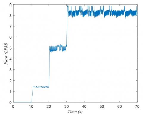
A schematic diagram of the experimental setup of the proposed system is demonstrated in Figure 2. A variable frequency motor was used to drive the inlet throttled three piston pump so that the pump was tested under various values of angular speed. The pump volumetric displacement was 1.3375×10⁻⁶ m3/rad. A charge pump was used that was driven by a constant speed motor was used to deliver the hydraulic fluid with a constant inlet pressure (Pin). The pump was tested under various valve input voltage, angular speed, inlet pressure, and supply pressure. In each test, flow and torque measurement were taken for 70 seconds with 0.2 ms intervals where the valve input voltage was changed each ten seconds while the inlet pressure, supply pressure, and the pump angular speed were kept constant. The sensors used in this work are described in Table 1. Samples of the raw data for the flow rate and torque are shown in Figures 3 and 4. Table 2 summarizes the measurement taken in this work.
Figure 2. A schematic diagram of the experimental setup
Table 1. Experimental measurements
|
Measured Quantity |
Sensor Information |
|
Discharge Pressure, Pd |
BT91760CC-102-15-002 (Setra) |
|
Inlet Pressure, Pi |
UB020867 40 (Setra) |
|
Inlet Flow, Qi |
KY18435224 (Gear type) |
|
Discharge Flow, Qd |
KY18438224 (Gear type) |
|
Applied Torque, T |
48202V(1-3) (Himmelstein +/-1000 in-lb) |
|
Motor Speed, ω |
Same as torque |
|
Inlet Valve Voltage, V |
NI DAQ card |
Table 2. Experimental measurements
|
Symbol |
Units |
Values |
|
|
||||
|
Pin |
MPa |
2 |
2.5 |
3 |
3.5 |
|
|
|
|
V |
Volts |
0 |
0.5 |
1 |
2 |
3 |
4 |
5 |
|
Ps |
MPa |
2 |
5 |
10 |
20 |
25 |
|
|
|
ω |
RPM |
1000 |
1500 |
|
|
|
|
|
Eqs. (18) and (19) were then written in a matrix form as shown in Eq. (20) where the matrix m represents the matrix of the quantities associated with the unknowns, n represents the unknowns vector, and F represents a vector of the terms of Eqs. (18) and (19) that have no unknowns. The quantities in the matrix m and the vector F are the experimental data and the unknowns in the n vector were determined as shown in Eq. (21). Table 3 summarizes the values of the unknowns of Eqs. (18) and (19).
$[m][n]=[F]$ (20)
$n=\left(m^T m\right)^{-1} m^T F$ (21)
Table 3. Unknowns of the flow and torque models
|
Dimensionless Quantity |
Physical Meaning |
Value |
|
$\hat{k}_0$ |
Fluid compressibility |
0.0015 |
|
$\hat{k}_1$ |
Low Re leakage |
0.0009 |
|
$\hat{k}_2$ |
High Re leakage |
0.0010 |
|
$\hat{A}$ |
Static friction |
0 |
|
$\hat{B}$ |
Boundary lubrication decay rate |
N/A |
|
$\hat{C}$ |
Hydrodynamic lubrication |
0.5631 |
|
$\hat{T} s$ |
Starting torque |
0.1257 |
|
$\hat{\varphi}$ |
Thermodynamic fluid property |
0.0941 |
Figure 3. Experimental ITP flow rate at 1000RPM, 2MPa inlet pressure and 25MPa supply pressure
Figure 4. Experimental ITP torque at 1000RPM, 2MPa inlet pressure and 25MPa supply pressure
Figures 5-16 represent the results of this work. In all figures, the theoretical results are represented by the solid lines while the markers represent the experimental results. Excellent agreement was achieved between the theoretical and experimental results, which indicates that the models proposed in this work are representative of the studied system and can be applied for various operating conditions. When the pump operates in the inlet throttling mode, both the volumetric efficiency and the mechanical efficiency are proportional to the valve opening are. Once the maximum flow rate for a certain speed is reached, the volumetric and mechanical efficiencies become independent of the valve opening area. Similarly, once the maximum flow is reached for a certain valve opening area, the volumetric and mechanical efficiencies become independent of the pump angular speed.
Figure 5. Supply flow rate versus valve opening area for 2 MPa inlet pressure and 25 MPa supply pressure
Figure 6. Supply flow rate versus pump angular velocity for 2 MPa inlet pressure and 25 MPa supply pressure
4.1 Supply flow rate results
Figures 5-8 illustrate the dimensionless supply flow rate of the pump under various operating conditions. It can be seen from Fig. 5 that along the inclined line, the supply flow rate is dependent of the valve position and the pump is in the throttling mode while along the horizontal lines, the flow is dependent of the angular velocity of the pump which indicates that the valve opening has reached its saturation value. The opposite can be seen in Figure 6 where the inclined line indicate that the flow rate is a function of the pump angular speed and the horizontal lines show that the flow rate is a function of the valve position and changing the pump speed does not change the flow rate. Figure 7 shows that increasing the supply pressure slightly reduces the pump flow rate due the increase in the leakage losses as the supply pressure increases. In addition, the input pressure does not have significant impact on the pump supply flow as shown in Figure 8.
Figure 7. Supply flow rate versus valve opening for 2 MPa inlet pressure and 1000 RPM velocity
Figure 8. Supply flow rate versus valve opening area for 25 MPa supply pressure and 1000RPM velocity
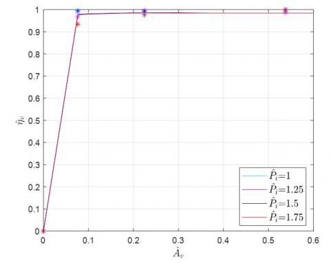
Figure 9. Volumetric efficiency versus valve opening area for 2 MPa inlet pressure and 25 MPa supply pressure
4.2 Volumetric efficiency results
Figures 9-12 show the theoretical and experimental volumetric efficiency of the system under various operating conditions. It can be seen from these figures that the system has great volumetric efficiency. It can also be seen that the pump rotational speed, the inlet pressure, and that valve opening area have no significant impact on the volumetric efficiency. The volumetric efficiency decreases as the pressure that the pump supply increases due to the leakage loss increase.
Figure 10. Volumetric efficiency versus pump velocity for 2 MPa inlet pressure and 25 MPa supply pressure
Figure 11. Volumetric efficiency versus valve opening area for 2 MPa inlet pressure and 1000RPM velocity
Figure 12. Volumetric efficiency versus valve opening area for 25 MPa supply pressure and 1000RPM velocity
4.3 Mechanical efficiency results
The mechanical efficiency of the inlet throttled pump is shown in Figures 13-16. Figure 13 shows that the mechanical efficiency increases as the valve opening area and the supply pressure increase when the pump runs in the throttling mode. Once the valve opening area is saturated, the mechanical efficiency becomes independent of the valve opening area. It can be seen from Figure 14 that when the pump is not in the throttling mode, the mechanical efficiency is dependent of the pump speed only and it slightly decreases as the pump velocity increases and the curves coincides with each other. Once the pump enters the throttling mode, the mechanical efficiency becomes proportional to the valve opening area. The mechanical efficiency increases as the pump speed decreases as illustrated in Figure 15. Figure 16 demonstrates that as the inlet pressure increases, the mechanical efficiency slightly increases. It is worth mentioning that the pump used in this study is originally designed to work under extremely high pressures (about 200 MPa) while in the real world hydraulic applications the working pressure is much lower than that. Therefore, using a pump that is designed to work under moderate pressures, under which hydraulic systems usually work, reduces the sizes of its parts which reduces the friction losses since the frictional losses are dependent of bearing size [23].
Figure 13. Mechanical efficiency versus valve opening area for an inlet pressure of 2MPa and 1000 RPM velocity
Figure 14. Pump mechanical efficiency versus pump velocity for an inlet pressure of 2MPa and supply pressure of 25 MPa
Figure 15. Pump mechanical efficiency versus valve opening area for an inlet pressure of 2 MPa and supply pressure of 25 MPa
Figure 16. Pump mechanical efficiency versus pump velocity for supply pressure of 25 MPa and 1000 RPM velocity
In this work, dynamic models for the flow rate, volumetric efficiency, and mechanical efficiency of a new flow control strategy using inlet throttling valve were proposed and validated experimentally. Excellent agreement between the mathematical models and the experimental results was achieved. The volumetric and mechanical efficiencies of the system were studied under a wide range of operating conditions. The results of this work represent a guide for the designers of this kind of systems to know the feasibility of these system and the sources of power losses and the weights of these losses so that improvements can be made. The conclusions drawn from this work can be summarized by the following:
1. The inlet throttled pump can be used as a flow control technique. It has a very high volumetric efficiency and an acceptable mechanical efficiency that can be improved by making enhancements to pump design according to the applications it is used for. This provides a great alternative of the available flow control methods used in airplanes, off-highway equipment and many other industrial applications in terms of efficiency, simplicity, and cost.
2. The pump angular velocity, the inlet pressure, and that valve opening area have no significant impact on the volumetric efficiency.
3. The volumetric efficiency is inversely proportional to the pressure that the pump supplies.
4. The mechanical efficiency is proportional to the valve position and the supply pressure when the pump runs in the throttling mode. However, the efficiency change is insignificant which indicates that the leakage losses are negligible.
5. The mechanical efficiency decreases as the pump angular velocity increases. As the inlet pressure increases, the mechanical efficiency slightly increases.
6. The inlet pressure has no significant effect on both the volumetric and mechanical efficiencies. This means that the charge pump may be replaced by an elevated tank to avoid the power consumed by the charge pump.
|
$\mathrm{A}$ |
static friction, dimensionless |
|
Av |
valve opening area, $\mathrm{m}^2$ |
|
$\bar{B}$ |
boundary lubrication decay rate, $N.s. \mathrm{m}^{-2}$ |
|
$\mathrm{C}$ |
hydrodynamic lubrication, $(N . m)^{\frac{1}{2}} \cdot m^{-1}$ |
|
$c_d$ |
discharge coefficient, dimensionless |
|
$k_0$ |
fluid compressibility, $\mathrm{m}^2 \cdot \mathrm{N}$ |
|
$k_1$ |
low Re leakage, $\mathrm{m}^3$ |
|
$k_2$ |
high Re leakage, $\mathrm{m}^4 \cdot \mathrm{s}^{-1} \cdot \mathrm{N}^{-1 / 2}$ |
|
$\dot{m}_{i n}$ |
mass inlet flow rate of the pump, $\mathrm{kg} . \mathrm{s}^{-1}$ |
|
$\dot{m}_{k}$ |
mass leakage flow rate of the pump, $\mathrm{kg} . \mathrm{s}^{-1}$ |
|
$\dot{m}_{s}$ |
mass supply flow rate of the pump, $\mathrm{kg} . \mathrm{s}^{-1}$ |
|
$P$ |
pressure inside the cylinder, $N \cdot m^{-2}$ |
|
$\bar{P}$ |
average pressure, $N \cdot m^{-2}$ |
|
$P_{\text {in }}$ |
inlet fluid pressure, $N \cdot m^{-2}$ |
|
$P_s$ |
supply fluid density, $N \cdot m^{-2}$ |
|
$P_1$ |
pressure at the pump inlet, $N \cdot m^{-2}$ |
|
$Q_{\text {in }}$ |
inlet fluid flow rate, $m^3 \cdot s^{-1}$ |
|
$Q_l$ |
leakage fluid flow rate, $m^3 \cdot s^{-1}$ |
|
$Q_s$ |
supply fluid flow rate, $m^3 \cdot s^{-1}$ |
|
$T$ |
actual torque, $N.m$ |
|
$V$ |
valve input voltage, volt |
|
$V_p$ |
pump volumetric displacement, $m^3 \cdot \mathrm{rad}^{-1}$ |
|
Greek symbols |
|
|
$\gamma$ |
camshaft angle, rad mass leakage flow rate of the pump, $\mathrm{kg} \cdot \mathrm{s}^{-1}$ |
|
$\beta$ |
fluid bulk modulus, $N. m^{-2}$ |
|
$\mu$ |
viscous friction factor $N. m^{-2}.s$ |
|
$\eta_m$ |
mechanical efficiency, dimensionless |
|
$\eta_v$ |
volumetric efficiency, dimensionless |
|
$\rho_{\text {in }}$ |
density of the inlet hydraulic fluid, $\mathrm{kg} . \mathrm{m}^{-3}$ |
|
$\rho_s$ |
supply fluid density, $\mathrm{kg} . \mathrm{m}^{-3}$ |
|
$\varphi$ |
thermodynamic fluid property, $N.m { }^{-2}.s$ |
|
$\omega_p$ |
pump angular velocity, $\mathrm{rad} . \mathrm{s}^{-1}$ |
[1] Zhao, L., Wang, J., Zhang, Z.W. (2017). Research on travel control system of hydrostatic transmission chassis. MATEC Web of Conferences, 139: 00212. https://doi.org/10.1051/matecconf/201713900212
[2] Hung, H.T., Ahn, K.K. (2010). Modeling and simulation of hydrostatic transmission system with energy regeneration using hydraulic accumulator. Journal of Mechanical Science and Technology, 24(5): 1163-1175. https://doi.org/10.1007/s12206-010-0313-8
[3] Coombs, D. (2012). Hydraulic efficiency of a hydrostatic transmission with a variable displacement pump and motor. http://hdl.handle.net/10355/33135.
[4] Lovrec, D., Tič, V. (2021). Speed-controlled hydraulic drive systems for heavy machinery. IMK-14 - Istrazivanje i Razvoj, 27(2): 61-72. https://doi.org/10.5937/IMK2102061L
[5] Cheng, M., Sun, B., Ding, R., Xu, B. (2023). A multi-mode electronic load sensing control scheme with power limitation and pressure cut-of for mobile machinery. Chinese Journal of Mechanical Engineering, 36: 29. https://doi.org/10.1186/s10033-023-00861-1
[6] Hu, D.M., Ding, S.B., Zhu, H.Q., Xu, B., Yang, H.Y. (2011). Velocity-tracking control of the variable-speed controlled hydraulic system: using compound algorithm of PD & feedforward-feedback control. In 2011 Third International Conference on Measuring Technology and Mechatronics Automation Shanghai, China, pp. 1109-1115. https://doi.org/10.1109/ICMTMA.2011.846
[7] Ali, H.H., Mustafa, A.W. Al-Bakri, F.F. (2021). A new control design and robustness analysis of a variable speed hydrostatic transmission used to control the velocity of a hydraulic cylinder. International Journal of Dynamics and Control, 9: 1078-1091. https://doi.org/10.1007/s40435-020-00716-w
[8] Ali, H., Obaid, S., Khafaji, S.O.W., Al-Bakri, F. (2021). H∞ loop shaping control design of the rotational velocity of a hydraulic motor. International Journal of Mechatronics and Applied Mechanics, 1(10): 72-79. https://doi.org/10.17683/ijomam/issue10/v1.9
[9] Jing, Z., Qi, H. (2020). Design and calculation of hydraulic transmission system of loader. Journal of Physics: Conference Series, 1676: 012242. https://doi.org/10.1088/1742-6596/1676/1/012242
[10] Manring, N.D., Fales, R.C. (2019). Hydraulic Control Systems. John Wiley & Sons, Inc. https://doi.org/10.1002/9781119418528
[11] Ali, H.H., Fales, R.C., Manring, N.D. (2019). Modeling and control design for an inlet metering valve-controlled pump used to control actuator velocity via H-infinity and two-degrees-of-freedom methods. Journal of Dynamic Systems Measurement and Control, 141(11): 111006. https://doi.org/10.1115/1.4044182
[12] Aranovskiy, S., Losenkov, A., Vázquez, C. (2014). Position control of an industrial hydraulic system with a pressure compensator. In 22nd Mediterranean Conference on Control and Automation, Palermo, Italy, pp. 1329-1334. https://doi.org/10.1109/MED.2014.6961560
[13] Ji, X.H., Wang, C.W., Zhang, Z.Y., Chen, S., Guo, X.P. (2020). Nonlinear adaptive position control of hydraulic servo system based on sliding mode back-stepping design method. Proceedings of the Institution of Mechanical Engineers, Part I: Journal of Systems and Control Engineering, 234(4). https://doi.org/10.1177/0959651820949663
[14] Xu, B., Shen, J., Liu, S.H., Su, Q., Zhang, J.H. (2020). Research and development of electro-hydraulic control valves oriented to industry 4.0: A review. Chinese Journal of Mechanical Engineering, 33: 29. https://doi.org/10.1186/s10033-020-00446-2
[15] Šiljak, D. (2012). Decentralized Control of Complex Systems. Dover Books on Electrical Engineering, Dover Publications, Mineola, New York (USA).
[16] Dubonjić, L., Prodanović, S., Stojanović, V., Morato, M.M. (2023). PD controller design for a system of a valve controlled hydromotor. Engineering Today, 2(3). https://doi.org/10.5937/engtoday2300012D
[17] Wiens, T. (2016). Improving performance of a switched inertance buck converter via positioning of reservoir flow valve. Journal of Dynamic Systems Measurement and Control, 138(12): 124502. https://doi.org/10.1115/1.4034045
[18] Wiens, A.C., Van, D.V.J.D. (2017). Soft switching in switched inertance hydraulic circuits. Journal of Dynamic Systems Measurement and Control, 139(12): 121007. https://doi.org/10.1115/1.4036887
[19] Yuan, C.G., Pan, M., Plummer, A. (2018). A review of switched inertance hydraulic converter technology. Journal of Dynamic Systems, Measurement and Control: Transactions of the ASME, 142(5): 050801. https://doi.org/ 10.1115/1.4046103
[20] Ali, H. (2017). Inlet metering pump analysis and experimental evaluation with application for flow control. Doctoral dissertation, University of Missouri--Columbia. https://doi.org/10.32469/10355/63605
[21] Bordeasu, I., Popoviciu, M.O., Salcianu1, L.C., Ghera, C., Micu, L.M., Badarau, R., Iosif, A., Pirvulescu, L.D., Podoleanu, C.E. (2017). A new concept for stainless steels ranking upon the resistance to cavitation erosion. IOP Conference Series: Materials Science and Engineering, 163: 012002. https://doi.org/10.1088/1757-899X/163/1/012002
[22] Wang, Y., Daruta, G., Poirierb, T., Stellac, J., Liao, H.L., Planche, M.P. (2017). Ultrasonic cavitation erosion of as-sprayed and laser-remelted yttria stabilized zirconia coatings. Journal of the European Ceramic Society, 37(11): 3623-3630. https://doi.org/10.1016/j.jeurceramsoc.2017.04.037
[23] Hagen, S., Knippel, R., Dai, J., Ludois, D. C. (2015). Capacitive coupling through a hydrodynamic journal bearing to power rotating electrical loads without contact. In 2015 IEEE Wireless Power Transfer Conference (WPTC), Boulder, CO, USA, pp. 1-4. https://doi.org/10.1109/WPT.2015.7140181