Guoqi Zhang![]() | Xingwang Li
| Xingwang Li![]() | Ao Song
| Ao Song![]() | Liangping Zhao*
| Liangping Zhao*![]()
© 2024 The authors. This article is published by IIETA and is licensed under the CC BY 4.0 license (http://creativecommons.org/licenses/by/4.0/).
OPEN ACCESS
With the acceleration of urbanization, the volume of construction waste has increased rapidly, posing a challenge in effective utilization. Heat pump systems, known for their energy efficiency and environmental benefits, offer a promising solution by using construction waste as a low-temperature heat source. This not only mitigates the pollution caused by waste but also facilitates the efficient recycling and reuse of resources. While existing studies have mainly focused on performance evaluation of heat pump systems, research on using construction waste as a heat source is relatively sparse. Exploring this innovative heat source application could provide new directions for the development of heat pump technology. Despite achievements in performance evaluation and waste utilization, there are shortcomings such as a strong dependence on traditional heat sources, insufficient consideration of the unique properties of construction waste, and imperfect analysis methods for component exergy losses. This paper is divided into two main sections: the construction of a mathematical model for a heat pump system using construction waste as a low-temperature heat source, explaining the underlying principles; and a detailed analysis of the exergy losses in system components, proposing a method for performance evaluation. Through this research, the paper aims to provide new technical support for the recycling of construction waste, enhance the overall efficiency of heat pump systems, and advance the development of energy-saving and environmental technologies.
construction waste, low-temperature heat source, heat pump systems, performance evaluation, exergy analysis
As the process of urbanization accelerates, the quantity of construction waste has rapidly increased, making its effective utilization one of the urgent problems to be solved [1-4]. Heat pump systems, as efficient energy conversion devices, have the advantages of energy saving and environmental protection [5-11]. Using construction waste as a low-temperature heat source in heat pump systems not only reduces the pollution caused by solid waste but also achieves efficient resource recovery and utilization [12, 13]. Therefore, studying how to use construction waste as a low-temperature heat source in heat pump systems has significant practical significance and application prospects.
In existing research, there is substantial study on the performance evaluation of heat pump systems, but relatively less on using construction waste as a low-temperature heat source [14, 15]. Exploring the application of this new type of heat source can provide new ideas and directions for the development of heat pump technology. Additionally, this research not only helps to improve the efficiency of heat pump systems but also promotes the development of resource utilization of construction waste, thereby achieving the dual goals of energy saving and emission reduction [16-18]. Therefore, in-depth study of heat pump systems utilizing construction waste as a low-temperature heat source is of great theoretical and practical significance.
Although there have been certain achievements in the performance evaluation of heat pump systems and waste utilization, there are still some deficiencies [19-21]. For example, existing heat pump systems largely depend on traditional heat sources and do not fully consider the uniqueness of construction waste as a low-temperature heat source. At the same time, the exergy analysis methods for the components of heat pump systems are not yet perfect, making it difficult to comprehensively evaluate the overall performance of the systems [22-25]. Therefore, it is particularly necessary to further improve the mathematical models and exergy analysis methods of heat pump systems, and to optimize the performance evaluation of the components specifically.
The research content of this paper mainly includes two parts. Firstly, construct a mathematical model of a heat pump system using construction waste as a low-temperature heat source, explaining its basic principles. Secondly, analyze in detail the exergy losses of the components in the heat pump system, and propose a method for performance evaluation. Through these studies, this paper aims to provide new technical support for the resource utilization of construction waste, enhance the overall efficiency of the heat pump system, and promote the development of energy-saving and environmental protection technologies.
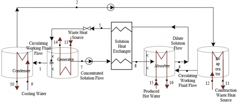
This paper adopts an improved heat pump system utilizing construction waste as a low-temperature heat source. The system uses a lithium bromide-water solution as the working fluid pair and includes five heat exchangers, a solvent pump, a solution pump, and components such as piping and valves connecting the devices. A schematic diagram of the system structure is shown in Figure 1.
The choice of lithium bromide-water solution (LiBr-H2O) as the working fluid pair for the heat pump system using construction waste as a low-temperature heat source is primarily due to its excellent absorption characteristics. Lithium bromide can effectively absorb water vapor, allowing the system to operate at lower temperatures, which is suitable for utilizing construction waste as a low-temperature heat source. Furthermore, the lithium bromide-water solution has stable thermodynamic properties over a wide range of temperatures. Its absorption and desorption processes can be efficiently conducted at lower temperatures and pressures, adapting to the low-temperature heat source provided by the construction waste.
The heat exchangers in the heat pump system specifically include evaporator, condenser, absorber, generator, and solution heat exchanger. Unlike traditional absorption heat pumps, the improved system uses construction waste as a low-temperature heat source, driving the heat source into the evaporator and generator to achieve heat recovery. Specifically, the residual heat from the construction waste acts as the driving heat source and enters the heat pump system in two modes: series and parallel. In series mode, the residual heat passes through the evaporator and generator sequentially; in parallel mode, the residual heat is split into two streams, each entering the evaporator and generator, respectively. The low-temperature heat source of construction waste in the evaporator generates saturated water vapor by absorbing the heat from the waste, which, after entering the absorber, is absorbed by the concentrated solution, releasing a large amount of heat and raising the dilute solution temperature to the absorption temperature. Through the solution heat exchanger, this heat is recovered and used to provide usable high-temperature hot water, achieving efficient recovery and reuse of the residual heat from construction waste. This heat pump system, utilizing construction waste as a low-temperature heat source, not only fully utilizes the residual heat of construction waste, reducing the waste's environmental impact, but also enhances the overall energy efficiency of the heat pump system and promotes the use of sustainable energy.
Figure 1. Schematic diagram of the heat pump system utilizing construction waste as a low-temperature heat source
To establish a steady-state concentrated model of the heat pump system utilizing construction waste as a low-temperature heat source, which reflects the real operating conditions and simplifies the thermodynamic calculations, the following assumptions are made in this paper:
(1) The outlet of the condenser is saturated water, the outlet of the evaporator is saturated vapor, and the outlet of the generator is superheated steam. Although the heat supply from construction waste may fluctuate, these state parameters are assumed to be constant for the sake of model simplification and computational feasibility.
(2) The work of the working fluid circulation pump and the solution pump is ignored. This is because the pump work has a relatively small proportion in the overall system energy balance and can be considered negligible, thus simplifying calculations.
(3) The enthalpy of the working fluid remains unchanged before and after throttling. This assumption helps simplify the thermodynamic calculations, although in practice, the enthalpy might change slightly.
(4) The lithium bromide solution at the outlets of the generator and the absorber is saturated. This assumption aids in determining the concentration and temperature of the solution, facilitating thermodynamic calculations.
(5) Frictional losses along the path and local resistances such as drag can be ignored, but to make the results more accurate, appropriate values of pressure loss can be taken. This means that specific pressure drops at various points are not detailed in the calculations, but a comprehensive value of pressure loss is introduced to improve the accuracy of the model.
(6) The system does not exchange heat with the outside environment. This assumption simplifies the calculations of the system’s energy balance, although in actual applications, there may be minor heat exchanges with the external environment.
(7) The system is in a steady flow state. Assuming that the system operates stably helps simplify calculations of dynamic changes, thus focusing on performance evaluation under steady-state conditions.
To accurately assess system performance, it is necessary to construct thermal load equations, temperature difference equations, pressure drop equations, and concentration difference equations for each device in the single-stage heat pump system.
Firstly, thermal load equations describe the heat absorbed or released by each device during a specific period. Using the principle of energy conservation, the thermal loads of the evaporator, condenser, generator, and absorber can be calculated. In the evaporator, the heat provided by the low-temperature heat source of construction waste causes the refrigerant to evaporate; in the condenser, the refrigerant releases heat and condenses into liquid; in the generator, the lithium bromide solution produces superheated steam by absorbing external heat; in the absorber, the solution absorbs the steam produced by the evaporator and releases heat. Through these calculations of thermal loads, the overall energy efficiency of the system can be determined. The thermal loads of the evaporator, generator, absorber, and condenser are denoted as Wr, Wh, Wx, and Wz respectively; the enthalpy values at various state points are denoted as g1~g8; the flow rates of residual heat source and cooling water are denoted as le and lz respectively; the inlet and outlet temperatures of cooling water are denoted as sz1 and sz2; the inlet and outlet temperatures of the residual heat source are denoted as se and se1; the flow rate of working fluid is denoted as F. The circulation factor is denoted as β, and the heat load equation for the evaporator is:
${{W}_{r}}=F\left( {{g}_{3}}-{{g}_{2}} \right)={{l}_{e}}{{z}_{o}}\left( {{s}_{e}}-{{s}_{e1}} \right)$ (1)
The formula for calculating the heat load of the generator is:
${{W}_{h}}=F\left[ {{g}_{1}}+\left( \beta -1 \right){{g}_{7}}-\beta {{g}_{5}} \right]={{l}_{e}}{{z}_{o}}\left( {{s}_{e}}-{{s}_{e1}} \right)$ (2)
The formula for calculating the heat load of the absorber is:
${{W}_{x}}=F\left[ {{g}_{3}}+\left( \beta -1 \right){{g}_{8}}-\beta {{g}_{4}} \right]$ (3)
The formula for calculating the heat load of the condenser is:
${{W}_{z}}=F\left( {{g}_{1}}-{{g}_{2}} \right)={{l}_{z}}{{z}_{o}}\left( {{s}_{z1}}-{{s}_{z2}} \right)$ (4)
Temperature difference equations are used to describe the differences in inlet and outlet temperatures of the devices, reflecting the heat exchange effects of the equipment. In the evaporator and condenser, the temperature difference reflects the state change of the refrigerant; in the generator and absorber, the temperature difference reflects the heating and absorption processes of the solution. By analyzing these temperature differences, the heat exchange performance of the equipment can be optimized. The difference between the condensation temperature s2 and the outlet temperature of the cooling water sz2 is denoted by Δs1, the difference between the residual heat source outlet temperature se1 in the generator and the outlet concentrated solution temperature s7 is denoted by Δs2, the difference between the residual heat source outlet temperature se1 and the evaporation temperature s3 in the evaporator is denoted by Δs3, the difference between the dilute solution inlet temperature s4 and the concentrated solution outlet temperature s8 in the solution heat exchanger is denoted by Δsra, and the difference in temperature between the inlet and outlet of the cooling water is denoted by Δsz. The constructed temperature difference equations are:
${{s}_{2}}={{s}_{z2}}-\Delta {{s}_{1}}$ (5)
${{s}_{7}}={{s}_{e1}}-\Delta s$ (6)
${{s}_{3}}={{s}_{e1}}-\Delta {{s}_{3}}$ (7)
${{s}_{8}}={{s}_{4}}-\Delta {{s}_{ra}}$ (8)
${{s}_{z1}}={{s}_{z2}}-\Delta {{s}_{z}}$ (9)
Pressure drop equations describe the pressure loss of fluids flowing within the equipment, reflecting the flow resistance in the system. For each device, including the evaporator, condenser, generator, and absorber, the pressure difference between the inlet and outlet needs to be calculated. Analyzing the pressure drop helps optimize fluid flow and reduce energy loss in the system. Concentration difference equations describe the concentration changes of lithium bromide solution in the absorber and generator. In the generator, the solution is heated and its concentration increases; in the absorber, the solution absorbs water vapor, reducing its concentration. By analyzing the concentration changes of the solution, the solution circulation can be optimized, enhancing the efficiency of the absorption and generation processes. Assuming the pressures inside the generator, condenser, evaporator, and absorber are denoted by o1~o4, the flow resistance of refrigerant steam in the generator and condenser is denoted by Δoh, the flow resistance of refrigerant vapor in the evaporator and absorber is denoted by Δox, and the concentration difference between concentrated solution ςh and dilute solution ςx is denoted by Δς, then the equations are:
$\Delta {{o}_{h}}={{o}_{1}}-{{o}_{2}}$ (10)
$\Delta {{o}_{x}}={{o}_{3}}-{{o}_{4}}$ (11)
$\Delta \varsigma ={{\varsigma }_{h}}-{{\varsigma }_{x}}$ (12)
Figure 2 shows the simulation flow diagram of the heat pump system using construction waste as a low-temperature heat source. The constructed heat pump system primarily consists of five main heat exchange components: an evaporator, a generator, an absorber, a condenser, and a solution heat exchanger. Based on the exergy loss calculation methods for these components, they can be divided into two categories. The first category includes the evaporator, generator, and solution heat exchanger. In these components, the evaporator and generator engage in heat exchange by absorbing low-temperature thermal energy from construction waste, which does not generate significant exergy losses during the heat exchange process itself. Their exergy losses primarily stem from the energy losses occurring during the transport of fluids. The solution heat exchanger only involves heat exchange between low-concentration and high-concentration solutions, thus its exergy losses also mainly arise from losses during the transport process. The second category includes the condenser and absorber. The condenser discharges heat to the environment through cooling water, which is not utilized by the system, leading to energy losses. In the absorber, the heat water exchanges heat with the lithium bromide solution, and similarly, part of the heat is not effectively used, resulting in combined losses of heat flow and thermal energy. The basic steps for analyzing the exergy losses of each component and the system's exergy efficiency are as follows:
(1) Calculation of exergy losses for the evaporator, generator, and solution heat exchanger.
Figure 2. Simulation flow diagram of the heat pump system using construction waste as a low-temperature heat source
For the exergy loss calculations of each component, the mass flow balance of the heat exchanger is the key. For the evaporator, generator, and solution heat exchanger, the exergy losses need to be assessed through the changes in mass flows. The evaporator and generator engage in heat exchange by absorbing low-temperature thermal energy from construction waste, which does not generate significant exergy losses during the heat exchange process itself, with losses mainly stemming from energy changes during the mass flow process. The exergy losses of the solution heat exchanger also primarily come from the internal heat exchange process between fluids. Specifically, establish the mass flow balance equations, calculate the exergy losses of these three parts by measuring the input exergy from the low-temperature heat source of the construction waste and the output exergy of the mass flows. The evaporator and generator utilize the low-temperature thermal energy from construction waste, and their exergy losses mainly stem from the energy changes in the mass flows. The exergy losses of the solution heat exchanger are also primarily derived from the internal heat exchange mass flow process. Assuming the value of the hot mass flow at the inlet of the heat exchanger is represented by Rg1, the value at the outlet by Rg2, the value of the cold mass flow at the inlet by Rz1, and the value at the outlet by Rz2, П represents the losses of the heat exchanger. For the heat exchanger, the following equation gives the mass flow exergy balance equation:
${{R}_{g1}}+{{R}_{z1}}={{R}_{g2}}+{{R}_{z2}}+\Pi $ (13)
(2) Exergy Loss Calculation for Condenser and Absorber
For the exergy loss calculation of the condenser and absorber, the condenser discharges heat to the environment through cooling water, which is not utilized by the system, resulting in energy loss. In the absorber, the heating water exchanges heat with the lithium bromide solution, and part of the heat is not effectively used, generating combined losses of heat flow and thermal energy. Thus, it is only necessary to calculate the exergy loss discharged to the environment and the total exergy loss of the heat flow and thermal energy. Assuming the mass flow rate of the hot stream is represented by Hg, the specific enthalpy of the hot stream at the heat exchanger inlet is denoted by gg1, the specific enthalpy of the hot stream at the heat exchanger outlet is denoted by gg2, the specific entropy of the cold stream at the heat exchanger inlet is denoted by tg1, the specific entropy of the cold stream at the heat exchanger outlet is denoted by tg2, the mass flow rate of the cold stream is represented by Hz, the specific enthalpy of the cold stream at the heat exchanger inlet is denoted by gz1, the specific enthalpy of the cold stream at the heat exchanger outlet is denoted by gz2, the specific entropy of the cold stream at the heat exchanger inlet is denoted by tz1, and the specific entropy of the cold stream at the heat exchanger outlet is denoted by tz2. The exergy loss equation for the heat exchanger flows is:
$\begin{align} & {{\prod }_{g}}={{H}_{g}}\left[ {{g}_{g1}}-{{g}_{g2}}-{{S}_{0}}\left( {{t}_{g1}}-{{t}_{g2}} \right) \right] +{{H}_{z}}\left[ {{g}_{z1}}-{{g}_{z2}}-{{S}_{0}}\left( {{t}_{z1}}-{{t}_{z2}} \right) \right] \\ \end{align}$ (14)
(3) Overall System Exergy Efficiency Evaluation
Through the mathematical expression of the system exergy balance, the exergy input, output, and loss of the entire heat pump system can be evaluated. Through this comprehensive evaluation, the system's exergy efficiency can be calculated, measuring the effectiveness of using construction waste as a low-temperature heat source. Assuming the total losses of the heat pump system are denoted by ΔR, the field losses of the generator are denoted by ΔRh, the losses of the condenser are denoted by ΔRz, the losses of the evaporator are denoted by ΔRr, the losses of the absorber are denoted by ΔRx, and the losses of the solution heat exchanger are denoted by ΔRg. The following equation provides the mathematical expression for the system's exergy balance:
$\Delta R=\Delta {{R}_{h}}+\Delta {{R}_{z}}+\Delta {{R}_{r}}+\Delta {{R}_{x}}+\Delta {{R}_{g}}$ (15)
Assuming the efficiency of the heat pump system is denoted by λR, the heat load of the absorber is denoted by Wx, and the temperature of the high-temperature hot water at the absorber outlet is denoted by Sg. The following equation defines the efficiency of the heat pump:
${{\lambda }_{R}}=\frac{{{W}_{x}}\left( 1-\frac{{{S}_{0}}}{{{S}_{g}}} \right)}{{{W}_{x}}\left( 1-\frac{{{S}_{0}}}{{{S}_{g}}} \right)+\Delta R}$ (16)
In the heat pump system using construction waste as a low-temperature heat source, the focus is on analyzing the exergy losses of each component through mass flow changes and evaluating the overall efficiency through the system's exergy balance. Through these steps, the sources of energy loss in the system can be identified, and the system design can be specifically optimized to achieve more efficient energy utilization goals. Figure 3 shows the flow diagram for the performance study of the heat pump system using construction waste as a low-temperature heat source.
Figure 3. Flow diagram for performance study of heat pump system using construction waste as a low-temperature heat source
By calculating and analyzing the exergy losses of each component in the heat pump system, the impact of each component on the overall energy efficiency of the system can be clearly seen. According to the results in Table 1, the condenser has the highest exergy loss at 32.5478, accounting for 61.23% of the total system exergy loss, making it the component with the largest loss. This is followed by the generator, with an exergy loss of 7.9562, which accounts for 14.56% of the total loss. The exergy losses for the absorber and evaporator are 5.7895 and 3.8256 respectively, representing 10.9% and 7.21% of the total respectively. The solution exchanger has the smallest exergy loss at 3.2985, making up 6.23% of the total system loss. The total exergy loss for the entire system is 52.9874. These data indicate that the condenser is the main source of exergy loss within the heat pump system and should be the focus for performance optimization. From the experimental results, it is evident that the condenser and generator are the most critical components in the heat pump system, as their exergy losses account for the vast majority of the total system loss. The high percentage of loss in the condenser, at 61.23%, shows that the efficiency of heat transfer during the condensation process is one of the main factors affecting the overall performance of the system. Therefore, optimizing the design and operating conditions of the condenser can significantly improve the energy efficiency of the system. The generator's loss percentage at 14.56% also suggests the need for further research and improvement in its performance.
Table 1. Exergy loss calculations for each component of the heat pump system
|
Component |
Logarithmic Mean Temperature Difference |
Exergy Loss |
Exergy Loss Rate |
|
Evaporator |
17.5 |
3.8256 |
7.21 |
|
Generator |
8.1 |
7.9562 |
14.56 |
|
Condenser |
13.6 |
32.5478 |
61.23 |
|
Absorber |
9.4 |
5.7895 |
10.9 |
|
Solution Exchanger |
5.8 |
3.2985 |
6.23 |
|
Entire System |
|
52.9874 |
100 |
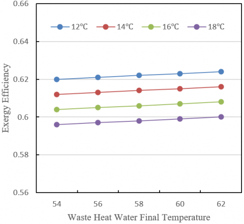
Figure 4. Impact of waste heat water final temperature and cooling water final temperature on exergy efficiency of heat pump system
According to the data in Figure 4, the final temperatures of waste heat water and cooling water significantly affect the exergy efficiency of the heat pump system. When the cooling water final temperature is 12°C, the exergy efficiency increases from 0.62 to 0.624 as the waste heat water final temperature rises from 54°C to 62°C. Similarly, with a cooling water final temperature of 14°C, the exergy efficiency increases from 0.612 to 0.616 as the waste heat water final temperature rises. For cooling water final temperatures of 16°C and 18°C, the exergy efficiency increases from 0.604 to 0.608 and from 0.596 to 0.6, respectively, with rising waste heat water temperatures. These data indicate that lower cooling water temperatures yield higher system exergy efficiency, and increasing the waste heat water temperature also helps improve the system’s exergy efficiency. The analysis concludes that lower cooling water temperatures result in higher system exergy efficiency, and as the waste heat water temperature rises, the system’s exergy efficiency further improves. This suggests that reducing the final temperature of cooling water and increasing the final temperature of waste heat water can effectively enhance the overall efficiency of the system.
Figure 5. Impact of waste heat water final temperature and cooling water final temperature on the coefficient of performance of the heat pump system
According to the data in Figure 5, the waste heat water and cooling water final temperatures significantly impact the coefficient of performance of the heat pump system. When the cooling water final temperature is 12°C, the coefficient of performance increases from 0.484 to 0.488 as the waste heat water final temperature rises from 54°C to 62°C. Similarly, with a cooling water final temperature of 14°C, the coefficient of performance increases from 0.4825 to 0.4865 as the waste heat water temperature rises. For cooling water final temperatures of 16°C and 18°C, the coefficient of performance increases from 0.481 to 0.485 and from 0.4795 to 0.4835, respectively. These data show that as the waste heat water temperature increases, the system’s coefficient of performance gradually increases, and lower cooling water temperatures also help improve the system’s performance. The conclusion is that raising the waste heat water final temperature and lowering the cooling water final temperature can significantly enhance the system’s coefficient of performance. This finding suggests that optimizing the temperature parameters of waste heat water and cooling water is an effective strategy for enhancing system performance.
(a) Heat load
(b) Performance coefficient
Figure 6. Dynamic response of heat pump system’s heat load and coefficient of performance when waste heat water inlet temperature increases by 10°C
According to the data in Figure 6, when the waste heat water inlet temperature increases by 10°C, there is a significant dynamic response in the heat loads of the absorber and the combined condenser + generator, as well as in the coefficient of performance of the heat pump system. At time point 0, the heat load of the absorber remained at 140 and gradually decreased to 100 before the 300 time point, then gradually recovered back to 140. The total heat load of the condenser and generator remained at 280 at time point 0, then spiked to 700 at the 100 time point, dropped to 350 at the 200 time point, and stabilized at 280 by the 300 time point. The coefficient of performance started at 0.48 at time point 0, dropped to 0.2 at the 100 time point, then gradually rose, reaching 0.45 by the 200 time point, and eventually returned to 0.48 by the 300 time point. The analysis of the dynamic response of the heat pump system’s heat load and coefficient of performance when the waste heat water inlet temperature increases by 10°C concludes that temperature changes have a significant impact on system performance. In the initial stages of the temperature increase, the heat load of the absorber decreased, while the total heat load of the condenser and generator significantly increased, and the system’s coefficient of performance notably declined. This indicates that the efficiency of heat transfer in the system decreased initially, leading to a temporary performance drop. However, as time progressed, the system gradually adapted to the new temperature conditions, with heat load and coefficient of performance returning to initial levels, demonstrating the system’s good self-regulating capability.
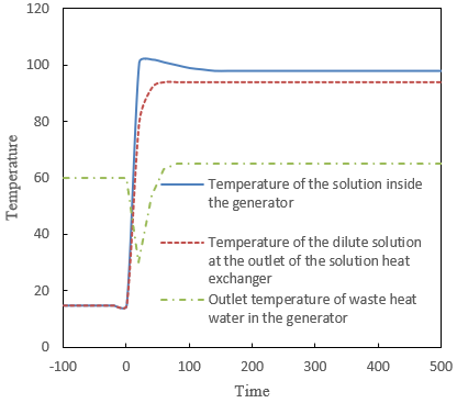
According to data from Figure 7(a), at time point 0, the temperature of the solution inside the generator and the temperature of the dilute solution at the outlet of the solution heat exchanger are both 15°C, with the waste heat water outlet temperature at 60°C. When the waste heat water inlet temperature increases by 10°C, the temperature of the solution inside the generator rapidly rises, reaching 102°C at the 100 time point, then gradually declines and stabilizes at 98°C after the 200 time point. The temperature of the dilute solution at the outlet of the solution heat exchanger rises to 80°C at the 100 time point, reaches 94°C at the 200 time point, and remains stable. The waste heat water outlet temperature drops sharply to 30°C at the 100 time point, then gradually recovers and stabilizes at 65°C by the 300 time point. These data indicate that during the initial phase of temperature changes, the parameters fluctuated sharply, then gradually stabilized. The analysis of the dynamic response data for generator temperature and waste heat water temperature concludes that, initially, the system's parameters quickly adjusted to new temperature conditions, showing significant temperature fluctuations. The solution temperature inside the generator and the dilute solution temperature at the solution heat exchanger outlet initially rose sharply, then gradually stabilized, indicating the system has strong heat transfer and self-regulating capabilities under the influence of rising temperatures. The waste heat water outlet temperature initially dropped sharply, then gradually rose and stabilized at a higher temperature, indicating effective use of waste heat in the initial phase, followed by the system reaching a new thermal equilibrium.
(a) Generator temperature and waste heat water temperature
(b) Absorber temperature and heating water temperature
(c) Evaporator temperature and waste heat water temperature
(d) Condenser temperature and cooling water temperature
Figure 7. Dynamic response of the heat pump system at startup
According to data from Figure 7(b), at time point 0, the temperature of the solution inside the absorber and the temperature of the concentrated solution at the outlet of the solution heat exchanger were both 15°C, with the produced hot water outlet temperature at 71°C. As the waste heat water inlet temperature increased by 10°C, the temperature of the solution inside the absorber quickly rose to 68°C at the 100 time point, reached 80°C at the 200 time point, and stabilized at 82°C by the 300 time point. The temperature of the concentrated solution at the outlet of the solution heat exchanger followed a similar trend, rising to 70°C at the 100 time point, reaching 82°C at the 200 time point, and stabilizing at 84°C at the 300 time point. The produced hot water outlet temperature dropped sharply to 41°C at the 100 time point, then quickly recovered, reaching 74°C at the 200 time point, and stabilized at 76°C by the 300 time point. These data show that during the initial phase of temperature changes, the parameters fluctuated sharply, then gradually stabilized. The analysis of the dynamic response data for absorber temperature and heating water temperature concludes that, initially, the system's parameters quickly adjusted to new temperature conditions, showing significant temperature fluctuations. The temperature of the solution inside the absorber and the concentrated solution temperature at the solution heat exchanger outlet initially rose sharply, then gradually stabilized, indicating the system has strong heat transfer and self-regulating capabilities under the influence of rising temperatures. The produced hot water outlet temperature initially dropped sharply, then gradually rose and stabilized at a higher temperature, indicating that the heat pump system effectively utilized temperature changes to enhance hot water output in the initial stage, followed by the system reaching a new thermal equilibrium.
Based on data from Figure 7(c), at time point 0, both the inlet temperature of waste heat water in the evaporator and the temperature of the solution inside the evaporator were 15°C. As the waste heat water inlet temperature increased by 10°C, the waste heat water inlet temperature in the evaporator quickly rose to 55°C at the 100 time point, reached 64°C at the 200 time point, and eventually stabilized at 66°C at the 300 time point. The temperature trend of the solution inside the evaporator was similar to that of the waste heat water inlet temperature, rising to 55°C at the 100 time point, reaching 67°C at the 200 time point, and stabilizing at 69°C at the 300 time point. These data indicate that there was a sharp initial fluctuation in parameters, which then gradually stabilized. The analysis of the dynamic response data for the evaporator temperature and waste heat water temperature concludes that initially, the system's parameters rapidly adjusted to new temperature conditions, showing significant temperature fluctuations. The waste heat water inlet temperature and the solution temperature inside the evaporator initially rose sharply, then gradually stabilized, indicating strong heat transfer and self-regulating capabilities under the effect of the temperature increase, showing that the heat pump system effectively enhanced heat transfer efficiency during the initial stages, after which the system reached a new thermal equilibrium.
According to data from Figure 7(d), at time point 0, both the solution temperature inside the condenser and the cooling water outlet temperature were 15°C. As the system began operation, the solution temperature inside the condenser rose to 20°C at the 100 time point and remained stable thereafter. The trend in the cooling water outlet temperature was similar to that of the solution temperature inside the condenser, rising to 17°C at the 100 time point and remaining stable thereafter. These data suggest that after an initial rapid adjustment, the temperatures of the condenser and cooling water stabilized, with only a small range of change. The analysis of the dynamic response data for the condenser temperature and cooling water temperature concludes that initially, the temperatures of the condenser and cooling water quickly adjusted and stabilized shortly thereafter, indicating good heat transfer and stability performance under the effect of temperature increases. The small range of change in the solution temperature inside the condenser and the cooling water outlet temperature indicates significant temperature regulation by the condenser in the system, effectively maintaining stable operation.
The research content of this paper has two parts. First, a mathematical model of a heat pump system using construction waste as a low-temperature heat source was constructed, and its basic principles were detailed. Second, the exergy losses of the components within the heat pump system were analyzed in depth, and a method for evaluating system performance was proposed. In the experimental part, the exergy losses of the heat pump system components were calculated, the effects of the final temperatures of waste heat water and cooling water on the system's exergy efficiency and coefficient of performance were studied, and the dynamic responses of the heat pump system's heat load and coefficient of performance to a 10°C increase in waste heat water inlet temperature, as well as the dynamic responses at system startup, were analyzed. The experimental data show that initially, the system's parameters quickly adjusted to new temperature conditions, showing significant temperature fluctuations, then gradually stabilized. The absorber, evaporator, and condenser each significantly rose initially, then gradually stabilized, demonstrating strong heat transfer and self-regulating capabilities under the influence of temperature increases. The small range of change in the condenser solution temperature and cooling water outlet temperature shows that the system maintains good stability. The results also reveal the significant impact of the final temperatures of waste heat water and cooling water on the system's exergy efficiency and coefficient of performance, with notable enhancements in the system's heat load and coefficient of performance when the waste heat water inlet temperature increases by 10°C.
This paper, through the construction of a mathematical model and detailed experimental analysis, revealed the dynamic characteristics of a heat pump system using construction waste as a low-temperature heat source, providing a scientific basis for optimizing system design and operation. The results not only enriched the theoretical foundation of heat pump systems but also offered important practical implications, particularly in the use of construction waste resources for low-temperature heat sourcing, with significant environmental and economic benefits.
Despite revealing dynamic characteristics and performance, this research has limitations. The experimental data were primarily gathered under specific conditions; future research could consider the impact of more variables and operational conditions to more comprehensively evaluate system performance. Further studies could also explore long-term operational stability and economic assessments of the system, and incorporate intelligent control technologies to optimize the operational efficiency of heat pump systems, achieving more effective utilization of construction waste resources.
[1] Chen, Y., Pei, Z., Mao, X., Fan, L., Xu, M., Li, Y., Wang, D.S., Yi, J. (2024). Evaluation of electromagnetic scattering characteristics of construction solid waste—A theoretical study of solid waste identification. Science of The Total Environment, 927: 172312. https://doi.org/10.1016/j.scitotenv.2024.172312
[2] Wu, H., Kang, S., Zhang, H., Sun, Q., Shen, R., Shu, Z. (2023). Research of the workability, mechanical and hydration mechanism of coal gangue-construction solid waste backfilling materials. Construction and Building Materials, 408: 133833. https://doi.org/10.1016/j.conbuildmat.2023.133833
[3] Saluja, S., Somani, P., Gaur, A., Mundra, S., Ahmad, K. (2024). Stabilized municipal solid waste as an alternative to natural sand in paver block construction. Process Safety and Environmental Protection, 182: 1035-1046. https://doi.org/10.1016/j.psep.2023.12.032
[4] Yu, H., Zahidi, I., Liang, D. (2023). Sustainable porous-insulation concrete (SPIC) material: recycling aggregates from mine solid waste, white waste and construction waste. Journal of Materials Research and Technology, 23: 5733-5745. https://doi.org/10.1016/j.jmrt.2023.02.181
[5] Liu, X., Wang, D., Peng, X., Wang, G., Yang, Y. (2024). Experimental study on performance and compressor characteristics of transcritical CO2 heat pump system. Applied Thermal Engineering, 123524. https://doi.org/10.1016/j.applthermaleng.2024.123524
[6] Chen, M., Du, Q., Yu, T., Song, W., Lin, W., Feng, Z. (2024). Heating performance and optimization of ice source heat pump system with supercooled water. Applied Thermal Engineering, 239: 122082. https://doi.org/10.1016/j.applthermaleng.2023.122082
[7] Wang, L. Deng, S.H. (2022). Optimal operation control of composite ground source heat pump system. Power Engineering and Engineering Thermophysics, 1(1), 64-75. https://doi.org/10.56578/peet010107
[8] Zohri, M., Prabowo, Suwarno, Fudholi, A., Suyono, T., Priandana, E.P., Utomo, Y.S. (2023). Performance review of solar-assisted heat pump systems using solar collectors, PV, and PVT technologies. International Journal of Heat and Technology, 41(3): 657-665. https://doi.org/10.18280/ijht.410318
[9] Piancastelli, L. (2022). Continuous, high efficiency defrosting of air-to-air heat pumps. Power Engineering and Engineering Thermophysics, 1(1), 2-7. https://doi.org/10.56578/peet010102
[10] Omar, I., Saleh, A.A.M. (2023). A comprehensive review of design and operational parameters influencing airlift pump performance. Mathematical Modelling of Engineering Problems, 10(3): 1063-1073. https://doi.org/10.18280/mmep.100342
[11] Cheng, Y.G., Wu, Y.Q., Bai, S.R. (2021). A smart community waste heat recovery system based on air source-sewage source compound heat pump. International Journal of Heat and Technology, 39(2): 503-511. https://doi.org/10.18280/ijht.390220
[12] Kezier, D., Cheng, J. H., Li, X. Y., Cao, X., Zhang, C. L. (2024). A semi-cascade heat pump system for different temperature lifts. Applied Thermal Engineering, 236: 121767. https://doi.org/10.1016/j.applthermaleng.2023.121767
[13] Li, K., Kong, F., Luo, S., Liu, N., Zhang, H., Dou, B., Zhao, Y., Zhou, X., Tu, R., Su, L., He, Q. (2024). Influence of lubricating oil circulation characteristics on the performance of electric vehicle heat pump system under low temperature conditions. Applied Thermal Engineering, 236: 121601. https://doi.org/10.1016/j.applthermaleng.2023.121601
[14] Li, P., Yuan, Y., Cao, X. (2023). Research on improving measurement accuracy of low temperature waste heat pump system of temperature sensor. AIP Advances, 13(7): 075003. https://doi.org/10.1063/5.0157407
[15] Hu, X., Shi, C., Liu, Y., Fu, X., Ma, T., Jin, M. (2024). Advanced exergy and exergoeconomic analysis of cascade high-temperature heat pump system for recovery of low-temperature waste heat. Energies, 17(5): 1027. https://doi.org/10.3390/en17051027
[16] Jiang, Y., Ma, G., Gong, Y., Wang, L. (2023). Simulation research of a dual-loop booster heat pump system on district heating under ultra-low temperature. Applied Thermal Engineering, 228: 120475. https://doi.org/10.1016/j.applthermaleng.2023.120475
[17] Mei, S., Lu, X., Zhu, Y., Wang, S. (2021). Thermodynamic assessment of a system configuration strategy for a cogeneration system combining SOFC, thermoelectric generator, and absorption heat pump. Applied Energy, 302: 117573. https://doi.org/10.1016/j.apenergy.2021.117573
[18] Yang, B., Jiang, Y., Fu, L., Zhang, S. (2018). Experimental and theoretical investigation of a novel full-open absorption heat pump applied to district heating by recovering waste heat of flue gas. Energy and Buildings, 173: 45-57. https://doi.org/10.1016/j.enbuild.2018.05.021
[19] Vialetto, G., Noro, M., Rokni, M. (2019). Studying a hybrid system based on solid oxide fuel cell combined with an air source heat pump and with a novel heat recovery. Journal of Electrochemical Energy Conversion and Storage, 16(2): 021005. https://doi.org/10.1115/1.4041864
[20] Li, H., Liang, F., Guo, P., He, C., Li, S., Zhou, S., Deng, L., Bai, C.Y., Zhang, X.F., Zhang, G. (2020). Study on the biomass-based SOFC and ground source heat pump coupling cogeneration system. Applied Thermal Engineering, 165: 114527. https://doi.org/10.1016/j.applthermaleng.2019.114527
[21] Aydin, D., Casey, S. P., Chen, X., Riffat, S. (2018). Numerical and experimental analysis of a novel heat pump driven sorption storage heater. Applied energy, 211: 954-974. https://doi.org/10.1016/j.apenergy.2017.11.102
[22] Yu, T., Wang, Y., Shi, W., Liang, C., Li, X., Cen, J., Luo, M. (2023). Performance analysis of a thermal management system for electric vehicles based on the three-fluid heat exchanger. Qiche Gongcheng/Automotive Engineering, 45(11): 2001-2013.
[23] Qiang, G., Fuxi, W., Yi, G., Yuanjun, L., Yang, L., Zhang, T. (2023). Study on the performance of an ultra-low energy building in the Qinghai-Tibet Plateau of China. Journal of Building Engineering, 70: 106345. https://doi.org/10.1016/j.jobe.2023.106345
[24] Ozcan, H.G., Hepbasli, A., Abusoglu, A., Anvari-Moghaddam, A. (2021). Advanced exergy analysis of waste-based district heating options through case studies. Energies, 14(16): 4766. https://doi.org/10.3390/en14164766
[25] Al-Zareer, M., Dincer, I., Rosen, M.A. (2018). Heat transfer and thermodynamic analyses of a novel solid–gas thermochemical strontium chloride–ammonia thermal energy storage system. Journal of Heat Transfer, 140(2): 022802. https://doi.org/10.1115/1.4037534