Mohammad Awwad Aldabbas![]()
© 2024 The author. This article is published by IIETA and is licensed under the CC BY 4.0 license (http://creativecommons.org/licenses/by/4.0/).
OPEN ACCESS
A water-cooled carbon steel coutant combustor type was designed, constructed, and operate to burn solid and liquid fuel. it was continuously operating without any cutout and without any technical problem conditions using different values of air-to-fuel ratios. It was discovered that when the air to fuel ratio increased, the amount of carbon monoxide in flue gas decreased. This was linked to an increase in carbon dioxide and a reduction in oxygen gas. The sulfur emission of mixtures of diesel and shale oil fuel was in general higher than that of the diesel fuel. However, carbon oxides emission was almost not affected by increasing the percentage of shale oil in the mixture. The obtained data were compared against those of diesel flame.
exhaust gases analysis, dry gas losses, incomplete combustion, combustion efficiency, volumetric product concentration
The energy utilization in the world is increasing at a high rate. Considering the present rate of energy consumption and the steady increase in population, very large demand for energy will undoubtedly occur by the turn of this century. This calls for technical innovations to reduce energy use or more effective use of energy. This is accomplished through further development and widespread use of renewable energy sources, and development of energy conservation and management technology. The accelerated research and development for alternative energy resources to augment the dwindling supply of petroleum and natural gas is currently under way throughout the world. Solid fuels have, in past, been the most common energy sources for large central generating station. These solid fuels have recently shared the market with gas and oil as the supplies of these alternative fuels decrease. It is likely that coal will return to a more dominant role in the combustion of solid fuels.
Jordan is a non-producing oil country with a limited source of energy. As a result, the country has to allocate a significant portion of the national income to cover the cost of the imported oil. However, the country Juna substantial reserves of oil shale which represent an untapped source of indigenous fossil fuel for the country. The Kingdom has been investigating methods of economically utilizing this fuel resource for over a decade. Until recently, most of this effort has been directed towards retorting processes to extract oil from the oil shale, and direct combustion of oil shale to generate electric power. The Jordanian oil shale is considered to have too low a fuel quality to be effectively used in conventional combustion process. However, in recent years, the circulating fluidized bed combustion process has demonstrated at commercial scale the ability to effectively utilize low grade fuels [1]. It is well known that the large quantities of oil shale exist in Jordan which are not widely used due to the following problems:
Carbon and/or hydrogen are the main components of all traditional fossil fuels, whether they be solid, liquid, or gas. These substances inevitably react with oxygen in the atmosphere to produce carbon monoxide, carbon dioxide, or water vapor. You may use the heat energy that is generated during combustion to heat your home [2]. The liquid fuels burn in two ways: either as fine droplets that evaporate when mixing with the air steam and burning, or as they vaporize and mix with the atmosphere prior to ignition, acting like gaseous fuels. Either the fuel and air are combined in a burner before the gaseous fuels are burnt, or the fuel and air enter a burner or furnace separately and mix together as the combustion process progresses. The first type of burning given a premixed flame whereas the second type is called burning with a diffusion flame.
Gaseous fuels have a number of advantages over a solid or liquid fuels. They burn without any smoke and ash, their combustion is complete with a small percentage of excess air, and the control of gas flames is relatively easy. The disadvantage in the difficulty in storing large quantities of gaseous fuels as compared to liquid and solid fuels. The combustion reactions can, therefore, be dealt with the help of new simple reaction equation which cover the combustion of other types of fuel as well. The Surface area of the liquid and solid fuels exposed to the air or oxygen in usually very small. The surface area of the liquid exposed to the air can be increased by reducing the size of liquid droplets or size of particle of a solid. The liquid fuel can be evaporated and mixed with air before combustion by breaking the liquid into small particles and providing sufficient space for these processes to take place.
The combustion of liquid fuel consists of the following processes: The mixing of spray with air, its evaporation, and the combustion of the mixture in case of a solid fuel, the atomization step can be eliminated if it is injected inside the combustion chamber as a dust e.g. coal. Also, the process of atomization and mixing are eliminated if a solid fuel bed is used. The combustion of a solid fuel also includes the evaporation process, which is negligible in most case. The major difference between the solid and liquid fuels: the combustion of all hydrocarbon fuels occurs in the MPOR phase. But solids may be considered to evaporate according to the equation established for liquid fuels.
Liquid fuel can combust in various forms such as vapor, small droplets, or pools, depending on the size of the liquid droplet. The combustion behavior of fuel droplets in a spray can be categorized as follows: In the preheat zone of an existing flame front, if the concentration of droplets is high and they are sufficiently small, they may evaporate and mix by diffusion with the air. Conversely, if the droplets are large and the distance between them is significant, they may burn as diffusion flames in the local atmosphere surrounding them. Droplet combustion can be further classified into two types: bipropellant combustion and monopropellant combustion. In bipropellant combustion, fuel and oxidant diffuse from opposite directions, forming a flame at the contact surface. In contrast, monopropellant droplets evaporate and decompose exothermally.
The solid fuels are burned in beds in chunck or pellet form or in pulverized form suspended in the air stream. When piece of coal is gradually heated in a furnace in presence of air, the water vapor from coal is released as the temperature is raised, this process gets over at about 100℃, the decomposition of its unstable compounds starts. This coal now starts emitting volatile gaseous, if the furnace temperature in sufficient to ignite the volatile matters, they will burn like the liquid fuel droplets which continuously supply the vapors as the drops are consumed. The coal piece remains dark during these processes because of the burning of the volatile matter around the coal piece, its temperature is raised but normally does not exceed 600℃ to 700℃. The flame gradually shortens and is extinguished when all gases get consumed. The piece which now remain is coke. If the rate of heating is very fast and the size of coal is very small, the coal particles. may be ignited before the volatile matter is completely burned.
The easiest fuels to store are gaseous ones, such as natural gas. Before burning, the gas requires little to no preparation. It may be lit by just putting it in a mixture with air. There are several methods to achieve this. One of the more popular types of gas burners is the atmospheric gas burner. These devices attract the main air into the burner by using the velocity of the incoming gas. The operation of these systems is normally satisfactory with primary sir gas premix from 310 to 70 percent. Secondary air is drawn in around the burner to complete the combustion process.
Flames manifest as thermal waves propelled by rapid exothermic chemical reactions traveling at subsonic velocities, shaped primarily by the flame pattern of the mixture or products and the quenching effect of solid surfaces. In pre-mixed flames, dependable ignition and combustion necessitate a fuel/air combination consistently near stoichiometry richness or chemical balance. Conversely, diffusion flames arise when the oxidizer and combustible are not premixed before entering the reaction zone, resulting in a diffusion flame type. Fuel droplets burning independently represent a form of diffusion flame.
5.1 Multiphase phenomena and complex scenarios modeling require more advanced techniques
One of the main objectives in solid fuel combustion research is the development of comprehensive computer models to help design combustors and furnace for clean and efficient utilization of solid fuel. These models must consider a number of complex, simultaneous and interdependent processes like fluid flow, turbulence, particle trajectory, heat transfer, and homogenous and heterogeneous chemical reactions, which make them good instrument in combustion research. In particular, they can yield information on flame stability, nitrogen oxides (NOx) formation, carbon burnout and ash formation. Performing such tasks experimentally is expensive, both in time and resources, therefore the use and development of computational models is becoming an important issue in combustion.
The solution to these models is not analytically and the only ways to solve all these non-linear coupled equations are by numerical methods. The numerical method is of a great importance as an improper solution method may give completely wrong answer even for a well-proposed physical model.
The present article is concentrated on experimental work in which coutant combustor type were built and tested.
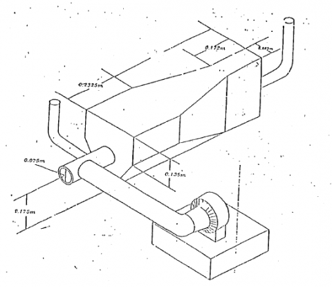
The experiments were conducted in a combustion chamber, several instruments were used to measure the mass of air consumption, temperature of the flame inside the combustor along the axes of the nozzle tip, and along the vertical axes from the nozzle tip, mass of fuel consumption, stack ten, untarred, and volumetric product concentration. A general view of the combustor rig and instruments are shown in Figure 1.
Operating Parameters
Gaseous emission, temperature, pressure, fuel consumption, air mass, flame temperature.
Instrument
The temperature, pressure, and emission of gaseous matter throughout the coutant type were measured by Chromel/Alumel. thermocouple 200℃ to +1260℃, pitot tube was used to measure pressure difference and separated fennel, gas analyzer was utilized to determine the volumetric concentration.
Figure 1. Coutant combustor type
The combustor is of a coutant type which horizontally oriented and it in cooled by means of a water jacket. An air blower is used to supply the combustor with the necessary. combustion air.
Initially, on attempt was carried out to construct the combustor rig by welding two halves of casted metal, unfortunately and during the welding it was realized that some welded joint broken due to light thermal stress. Then it was decided to nee carbon steel sheet to build the rig instead of cast iron since it is much easier to weld this type of material. The combustor wall construction must be one that will resist and build up and tolerate the erosive action of wall blowers to remove any accumulated ash [3-16]. To ensure continuity in operating conditions the combustor bottom must be designed for continuous ash removal. This suggests the use of a coutant type bottom where wall Labe are bent to form the hopper shaped bottom, with ash being discharged to a hopper through the narrow opening. The opening must be kept small to prevent slagging in the ask hopper by excessive leakage radiation.
The combustor flame tube is made from carbon steel sheets to withstand high temperature., it is cooled by water jacket. The following holes are drilled in the wall:
I. A 0.10×0.20 m² rectangular hole on the top of the combustor was covered with 0.15×0.27 m² rectangular glass of thickness 0.013 m, it was need to observe the flame temperature, shape, length and color.
II. Two circular pipe hole of 0.070 m length on the side view of combustor are welded to the wall table in which thermocouple are inserted inside these circular pipes.
III. A 0.07 m circular pipe hole on the side of the combustor was connected to a vacuum pump and a trap and it was used to collect the exhaust gas for samples.
The exhaust pipe is made from sheet metal with 0.10 m in diameter (stack diameter) and 10 m in the length to convey the gaseous product of the combustion above the building.it fixed with the combustor tube by means of flanges and bolts. The exhaust pipe has a hole drilled into it to withdraw sample of exhaust product and to measure the slack temperature.
An oil burner nozzle is a tool made to provide a set quantity of fuel to the combustion chamber at the spray angle and uniform pattern that work best for that burner. To expedite the vaporization required for combustion, the oil burner nozzle atomizes fuel oil. The nozzle component of an oil burner, the hollow cone and the solid cone are the two fundamental forms of spray cone patterns. The inlet nozzle is made from sheet metal with 0.16 m in diameter and 0.175 m in length. The nozzle is fixed with the combustor tube by means of flanges and bolts [15].
The air system used consists of the following:
The necessary combustion air was supplied by means of centrifugal blower driven by electric motor of constant speed, the air mass flow rate was controlled by two means of movable gate mounted at the blower suction, the first gate was used to control the primary air necessary for combustion, while the second gate (secondary air) was used for flame length controlling and turbulent air mixing, in other word, the mean function of the secondary air to enhance the combustion efficiency in the lean region (tich oxygen).
The air intake nozzle was 76 mm in diameter and made from sheet metal. The nozzle is connected to square box which is fitted on the suction line of the centrifugal fan. A pilot tube is attached to the nozzle tapping to measure the dynamic head and hence the velocity of air is calculated, thus the mass flow of air is calculated using:
mn=A*U*ρ*CD
where, A, U, ρ, CD is the nozzle area, stream velocity, stream density, the coefficient of discharge which was taken equal (625) respectively.
The fuel supply system comprises several components: a fuel pump to deliver the necessary fuel to the burner, a fuel tank positioned 2 meters above the burner to store the liquid fuel, a control valve installed on the main line, an electric motor to drive the fuel pump, a separate funnel for measuring fuel consumption, and a delivery pipe for returning unburned fuel to the main tank.
A pitot tube was used to measure pressure difference in order to measure the velocity of the stream. Applying Bernoulli equation the velocity of the stream is:
$\mathrm{U}=\sqrt{2 \mathrm{~g}\left(\mathrm{~h}_1-\mathrm{h}_2\right) / \mathrm{p}}$
where, $(\mathrm{h}_1-\mathrm{h}_2)$ is the deflection of the manometer in (mmH2o), ρ is the stream density(kg/m³), $\mathrm{U}$ is the velocity of the stream.
Fuel consumption
Where the specific gravity was found experimentally by dividing the density of the liquid fuel over the density of the water, and the volume of fuel consumption was read directly from separated fennel.
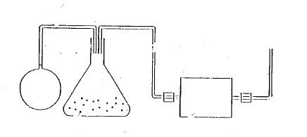
The gas sampling arrangement, as depicted in Figure 2, comprised several components: A vacuum air pump, a trap designed to absorb moisture and prevent it from entering the vacuum pump, consisting of a glass flask and absorbing material for moisture removal. A typical gas analyzer was utilized to determine the volumetric concentration of the exhaust gas. The flue gas sample was drawn into the trap to eliminate moisture content before introduction to the vacuum pump, with the resulting sample collected by a balloon for further analysis. Gas chromatography was employed to analyze the exhaust gas sample and investigate the volumetric product concentrations of carbon monoxide, carbon dioxide, oxygen, nitrogen, and sulfur.
Figure 2. Gas sampling arrangement
The heat generated during full combustion is less than the fuel's heating value because not all of the fuel is completely oxidized. The greatest heat loss occurs when hot exhaust gases rise beyond the temperature of entering air and fuel, a phenomenon known as dry gas loss (DGL) [13].
The DGL can be calculated using:
DGL=CP×(TS-Ta)
where, DGL, CP, TS are dry gas loss, specific heat of the flue gas (assumed to be equivalent to that of air), stack temperature, and air temperature respectively.
The energy lost due to the formation of carbon monoxide instead of carbon dioxide during combustion is termed as the incomplete combustion loss (ICL). This loss can be calculated by multiplying the mass of carbon burned per mass of fuel by the volumetric percentage of carbon monoxide in the exhaust gas, divided by the sum of the volumetric percentages of carbon monoxide and carbon dioxide. The equation for calculating ICL is as follows:
$\mathrm{ICL}=23030 * \mathrm{C}_{\mathrm{b}} * \frac{\mathrm{CO}}{\mathrm{CO}+\mathrm{CO}_2}$
where, ICL, Cb, CO, CO2 are represent the incomplete combustion loss, mass of carbon burned per mass of fuel, volumetric percentage of carbon monoxide in the exhaust gas, and volumetric percentage of carbon dioxide in the exhaust gas.
In the experimental setup, two distinct liquid fuels were employed. The primary fuel utilized was diesel fuel, a common choice in combustion experiments due to its widespread availability and well-understood combustion properties. Additionally, a blend of shale oil and diesel fuel was introduced into the experimental framework, providing an opportunity to explore the combustion characteristics of this composite fuel mixture.
The shale oil utilized in the experiment exhibited specific properties that influenced its combustion behavior. Notably, its specific gravity was measured at 0.081, indicating its relative density compared to water. The elemental analysis revealed a water content of 1.1% by weight, a crucial factor influencing combustion efficiency. Furthermore, the calorific value of the shale oil stood at 9180 Kcal/Kg, providing insight into its energy content. Other key properties included viscosity, measured at 8.47, and density, which was recorded as 0.8852.
In each experimental trial, a detailed and systematic procedure was adhered to ensure precise data collection. The shale oil, distinguished by its high viscosity, was subjected to preheating to enhance its handling and combustion efficiency. Concurrently, it was blended with low-viscosity diesel fuel to optimize combustion performance. Before each test, the mixture underwent purification through a paper filter to eliminate impurities and ensure clean combustion. The fuel tank was filled to capacity to establish a consistent starting point, while continuous cooling was maintained by circulating water within the jacket surrounding the combustor chamber. Close monitoring of the water supply and drainage ensured stable cooling conditions throughout the experiments. Manometer clamps were meticulously adjusted to zero readings to achieve accurate pressure measurements. Throughout the duration of each trial, pressure differentials and temperature distributions within the flame were monitored at regular five-minute intervals. Observations of flame length and color were diligently recorded to assess combustion characteristics accurately. Following one hour of continuous operation, the volume of diesel consumption was meticulously measured to evaluate fuel usage.
In addition to the experimental procedure, a series of six meticulously conducted experiments were designed to comprehensively examine the combustion characteristics of shale oil fuel. These experiments aimed to analyze key parameters such as volumetric product concentration, dry gas losses, and incomplete combustion efficiency. The preheating of the fuel to 23℃ was crucial to facilitate handling and combustion, particularly given the high viscosity of shale oil. Furthermore, the experimental setup involved blending shale oil with diesel fuel at varying proportions, ranging from 5% to 30%. This range of compositions allowed for a comprehensive investigation into combustion behavior under different fuel mixtures, offering valuable insights into combustion performance and efficiency across various scenarios.
Transient system analysis under varying inputs provides deeper insights.
During the experimental investigation, several notable observations were made, shedding light on the combustion process. Firstly, it was observed that the noise level of the combustor escalated with an increase in the mass of the fuel. Secondly, as both the mass of the fuel and the mass of air were augmented, there was a corresponding increase in the length of the flame. Additionally, when comparing a mixture of shale oil and diesel to diesel liquid fuel, it was evident that the flame length of the former surpassed that of the latter, attributable to the heightened flame temperature. Lastly, as the combustion reaction progressed through its stages after reaching steady state condition, the flame color transitioned to a lighter shade of orange due to enhanced mixing between the reactant and air. These observations offer valuable insights into the dynamic nature of combustion processes and provide a basis for further analysis and experimentation.
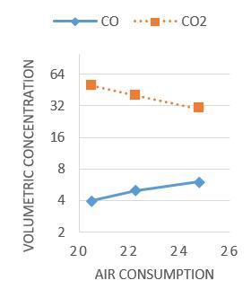
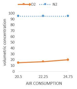
The experiments were specifically designed to investigate two primary factors: first, the volumetric product concentration of the main gaseous product, and second, the effect of air consumption on the volumetric concentration of the primary gaseous product while keeping the diesel fuel consumption constant. Figures 3 and 4 illustrate the impact of varying air consumption levels on the volumetric concentration of essential gaseous components, such as oxygen, nitrogen, carbon monoxide (CO), and carbon dioxide (CO2). These analyses aimed to provide insights into how changes in air intake affect the composition of combustion products, crucial for understanding and optimizing combustion processes.
Increasing air consumption leads to the oxidation of carbon monoxide to carbon dioxide, resulting in an increase in the volumetric concentration of carbon dioxide while decreasing the concentration of carbon monoxide due to improved combustion efficiency. Similarly, a general trend observed in the curves depicts an increase in nitrogen and carbon dioxide concentrations, alongside a decrease in oxygen and carbon monoxide concentrations with rising air consumption levels.
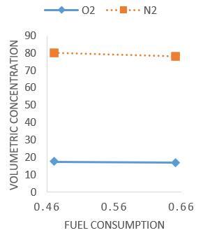
In contrast, when fuel consumption increases, the concentration of carbon monoxide rises while the concentration of carbon dioxide decreases due to incomplete combustion. This trend is illustrated in Figures 5 and 6, where an increase in fuel consumption results in a decrease in oxygen and carbon dioxide concentrations, coupled with a relative increase in carbon monoxide concentration.
Figure 3. Effect of air consumption on volumetric concentration of carbon monoxide and carbon dioxide at constant fuel consumption for diesel fuel
Figure 4. Effect of air consumption on volumetric concentration of oxygen and nitrogen at constant fuel consumption for diesel fuel
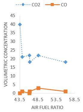
Figure 5. Effect of air fuel ratio on volumetric concentration of carbon monoxide and carbon dioxide at constant air consumption for diesel fuel
Figure 6. Effect of fuel consumption on volumetric concentration of oxygen and nitrogen at constant air consumption for diesel fuel
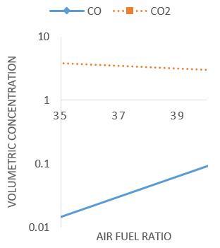
The impact of the air-fuel ratio on volumetric concentration is illustrated in Figures 7 and 8. As anticipated, the trend observed indicates an increase in the volumetric concentration of carbon monoxide and a decrease in carbon dioxide as the air-fuel ratio increases, indicative of incomplete combustion. Upon reaching the optimal air-fuel ratio, a shift occurs where the volumetric concentration of nitrogen and carbon monoxide decreases, while that of oxygen and carbon dioxide increases.
Figure 7. Variation of volumetric concentration of carbon monoxide and carbon dioxide with air fuel ratio for diesel fuel
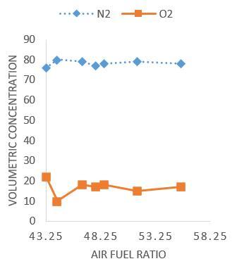
Figure 8. Variation of volumetric concentration of oxygen and nitrogen with air fuel ratio for diesel fuel
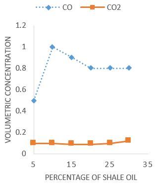
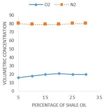
The influence of shale oil percentage on volumetric product concentration is depicted in Figures 9 and 10. The general trend observed in these curves indicates that the effect is similar to that of diesel fuel.
On other hand Jüri Loosaar et al. analyses the first data of Estonian oil shale industrial CFB firing in the light of almost 40 year experience of Estonian oil shale use in power production. They found that the very first operational experience of CFB units are very promising and all basic problems of oil shale pulverized firing like high air emissions (SO2 — 820–1360 mg/MJ; NOx — 90–110 mg/MJ), fouling and corrosion of heating surfaces, low efficiency and low operational reliability seemed to be solved. Oil shale CFB firing at much lower temperatures (∼800℃) than pulverized firing (∼1400℃) results only partial decomposition of oil shale contained carbonates, meaning lower specific fuel consumption values and decreased CO2 emissions. Also fly ash composition and properties has been changed, which results in different new prospectives of ash utilization possibilities, but also some additional ash land filling problems [17-22].
Figure 9. Variation of volumetric concentration of carbon monoxide and carbon dioxide with percentage of shale oil
Figure 10. Variation of volumetric concentration of oxygen and nitrogen with percentage of shale oil
Consequentely good agreementin combustion of oil shale in the coutant combustor and Estonian oil shale industrial CFB.
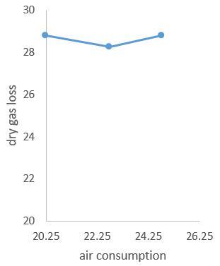
The influence of air consumption on dry gas combustion loss (DGL) is significant, primarily dependent on stack temperature and the mass of flue gas. Illustrated in Figure 11 is the impact of air consumption on the percentage of dry gas combustion loss (DCL) at a constant fuel consumption rate for diesel fuel. The general trend observed in this curve suggests that the variation of DGL remains relatively constant with increasing air consumption, attributed to a decrease in stack temperature.
Figure 11. Effect of air consumption on dry gas loss at constant fuel consumption for diesel fuel
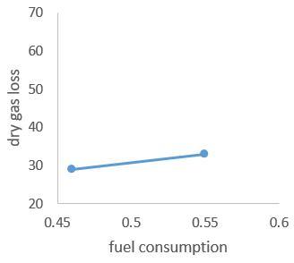
The impact of fuel consumption on dry gas combustion loss (DGL) is illustrated in Figure 12, depicting the percentage of dry gas combustion loss at a constant air consumption rate for diesel fuel. The general trend observed in this curve indicates a continuous increase in DGL as fuel consumption rises, attributed to the corresponding increase in stack temperature.
Figure 12. Effect of fuel consumption on dry gas loss at constant air consumption for diesel fuel
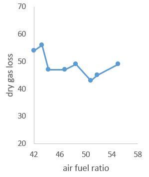
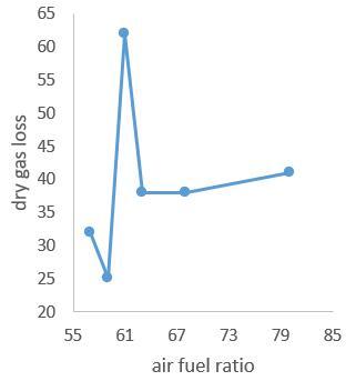
The effect of the air-fuel ratio on dry gas combustion loss (DGL) is depicted in Figures 13 and 14 for diesel fuel and a mixture of shale oil and diesel fuels, respectively. As anticipated, the general trend observed in these curves indicates that DGL increases with higher air-fuel ratios until reaching an optimal value, attributed to the increased stack temperature. Subsequently, with further increases in the air-fuel ratio, the percentage of DGL decreases due to the corresponding decrease in stack temperature.
Figure 13. Variation of dry gas loss with air fuel ratio for diesel fuel
Figure 14. Variation of dry gas loss with air fuel ratio for shale oil
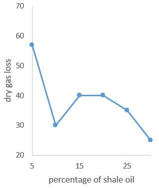
Figure 15. Variation of dry gas loss with percentage of shale oil for diesel fuel
The impact of shale oil percentage in the mixture on dry gas combustion loss is depicted in Figure 15. The general trend of this curve indicates a continuous decrease in DGL as the percentage of shale oil in the mixture increases. This decrease is attributed to the decrease in stack temperature associated with higher shale oil content.
20.1 Effects of stack temperature on dry combustion loss and dry gas loss
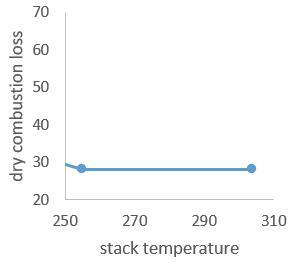
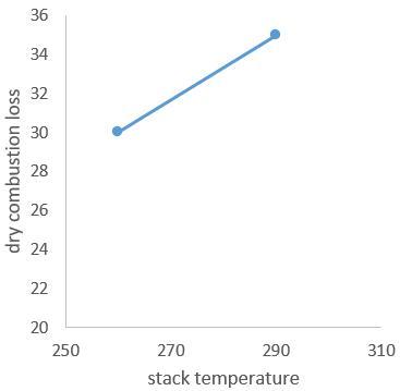
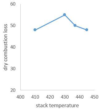
Figures 16 and 17 illustrate the effect of stack temperature on dry gas combustion loss for diesel fuel and a mixture of shale oil and diesel fuels, respectively. Dry gas combustion loss (DGL) is primarily influenced by stack temperature. Figure 16 demonstrates a continuous increase in DGL as fuel consumption rises, reflecting the corresponding increase in stack temperature. Conversely, Figure 17 indicates that DGL remains relatively constant with a relative increase in stack temperature.
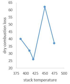
Moreover, Figures 18 and 19 depict the impact of air-fuel ratio on DGL. The general trend observed in these figures suggests that DGL increases with an increase in air-fuel ratio until reaching an optimum value, attributable to the increased stack temperature. Subsequently, with further increases in the air-fuel ratio, DGL decreases due to the corresponding decrease in stack temperature.
Figure 16. Variation of dry combustion loss percentage with stack temperature al constant air consumption for diesel fuel
Figure 17. Variation of dry combustion loss percentage with stack temperature at constant fuel consumption for diesel fuel
Figure 18. Variation of dry combustion loss percentage with stack temperature for diesel fuel
Figure 19. Variation of dry combustion loss percentage with stack temperature for mixture of shale oil & diesel fuels
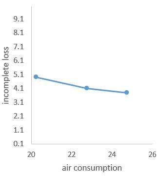
Figure 20. Effect of air consumption on incomplete loss for diesel fuel
Incomplete combustion loss (ICL) and its dependence on air consumption is depicted in Figure 20, focusing on diesel fuel at constant fuel consumption. The general trend observed in this curve demonstrates a continuous decrease in ICL with increasing air consumption. This decrease can be attributed to the reduction in carbon monoxide concentration and the simultaneous increase in carbon dioxide concentration as air consumption rises.
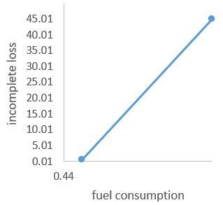
The impact of fuel consumption on incomplete combustion loss (ICL) at constant air consumption for diesel fuel is illustrated in Figure 21. The trend depicted in this curve indicates a continuous increase in ICL as fuel consumption rises. This increase is attributed to the increase in carbon monoxide (CO) concentration and the simultaneous decrease in carbon dioxide (CO2) concentration with higher fuel consumption levels.
Figure 21. Effect of fuel consumption on incomplete loss at constant fuel consumption for diesel fuel
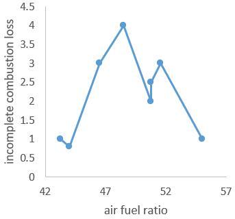
Figure 22 depicts the effect of air-fuel ratio on incomplete combustion loss for both diesel fuel and a mixture of shale oil and diesel fuels.
Figure 22. Variation of incomplete combustion loss with air fuel ratio for diesel fuel
The overall trend observed in these curves suggests that incomplete combustion loss (ICL) increases as the air-fuel ratio is increased until it reaches an optimum value. This increase is due to the rise in carbon monoxide (CO) concentration and the decrease in carbon dioxide (CO2) concentration. Subsequently, as the air-fuel ratio continues to increase beyond this optimal point, ICL decreases because carbon monoxide decreases while carbon dioxide increases.
Based on the findings of the current study, several conclusions can be drawn:
Limitations and recommendations for future work is needed.
Furthermore, the literature review and experimental investigation suggest several areas warranting further exploration, including:
These areas of research represent opportunities for enhancing our understanding of oil shale combustion processes and one of the limitations in the present work is capacity of combustor oil shale and its orientation.
[1] Ministry of Energy. (2021). Annual Report.
[2] Sharma, S., Moham, C. (1984). Fuels and Combustion, Tho MeGraw-hill Ic.
[3] Subramanian. (2013). Utilization of alternative fuels in internal combustion Engines/Vehicles. Alternative Transportation Fuels Utilization in Combustion Engines.
[4] Wang, S., Lu, H., Zhao, F., Liu, G. (2014). CFD studies of dual circulating fluidized bed reactors for chemical looping combustion processes. Chemical Engineering Journal, 236: 121-130. https://doi.org/10.1016/j.cej.2013.09.033
[5] Ohrn, T., Lee, S.I. (2010). Investigation and Design Studies of SOFC Electrode Performance at Elevated Pressure. Rolls-Royce Fuel Cell Systems (Us) Incorporated. https://doi.org/10.2172/1030645
[6] Galal, M.G., Aal, M.A., El Kady, M.A. (2002). A comparative study between diesel and dual-fuel engines: Performance and emissions. Combustion science and technology, 174(11-12): 241-256. https://doi.org/10.1080/713712964
[7] Zargar, O.A., Huang, R.F., Hsu, C.M. (2019). Effect of acoustic excitation on flames of swirling dual-disk double-concentric jets. Experimental Thermal and Fluid Science, 100: 337-348. https://doi.org/10.1016/j.expthermflusci.2018.09.018
[8] Maki, D.F., Prabhakaran, P. (2012). An experimental investigation on performance and exhaust emissions of compression ignition engine fuelled with palm oil methyl ester blends. In 2012 International Conference on Renewable Energies for Developing Countries (REDEC), pp. 1-5. https://doi.org/10.1109/REDEC.2012.6416680
[9] Chong, Y.O., Nicklin, D.J., Tait, P.J. (1986). Solids exchange between adjacent fluid beds without gas mixing. Powder technology, 47(2): 151-156. https://doi.org/10.1016/0032-5910(86)80111-5
[10] Midilli, A. (2004). Gasification of leather residues-part ii. conversion into combustible gases and the effects of some operational parameters. Energy Sources, 26(1): 45-53. https://doi.org/10.1080/00908310490251855
[11] Meng, X., Qi, Z., Yu, C., Bian, J., Ma, Z., Long, Q., Su, J. (2021). Solid-acid catalytic conversion of oil shale: Effects of sulfonic acid grafting on oil yield enhancing and quality improvement. ACS omega, 6(8): 5836-5845. https://doi.org/10.1021/acsomega.0c06264
[12] Culp. (1979). Principle of energy conversion. McGraw-hill, Inc.
[13] Stone, R. (1999). Introduction to internal combustion engines. London: Macmillan, 3.
[14] Audi. Heat and Ventilation Oil burners.
[15] O'Sulivan. Coal-Fired Process Ilenters. Energy Management, 87-91.
[16] Liu, Y., Jiang, J. (2023). Preparation of β-ionone microcapsules by gelatin/pectin complex coacervation. Carbohydrate Polymers, 312: 120839. https://doi.org/10.1016/j.carbpol.2023.120839
[17] Varde, K.S., Frame, G.A. (1983). Hydrogen aspiration in a direct injection type diesel engine-its effects on smoke and other engine performance parameters. International Journal of Hydrogen Energy, 8(7): 549-555. https://doi.org/10.1016/0360-3199(83)90007-1
[18] Khaleel, M., Yusupov, Z., Ahmed, A., Alsharif, A., Nassar, Y., EI-Khozondar, H. (2023). Towards Sustainable Renewable Energy. Renewable Energy Sources 59: 557–567. https://doi.org/10.3103/S0003701X23600704
[19] Abbasov, V.M., Mamedov, F.F., Ismailov, T.A. (2008). Heats of combustion of oil shale, bitumen, and their mixtures. Solid Fuel Chemistry, 42(4): 248-250.. https://doi.org/10.3103/S0361521908040113
[20] Shamsiev, K.A., Kh. Shamsiev, B. (2022). Ensuring safety of the functioning of a power system under the conditions of large-scale renewable energy source integration in the region of Central Asia. Applied Solar Energy, 58(5): 725-731. https://doi.org/10.3103/S0003701X2360008X
[21] Elistratov, V.V. (2022). Renewable energy trends within the concept of low-carbon development. Applied Solar Energy, 58(4): 594-599. https://doi.org/10.3103/S0003701X22040077
[22] Loosaar, J.R., Arro, H., Parve, T., Pihu, T.N., Prikk, A., Tiikma, T., Hiltunen, M. (2005). New 215 MWEL CFB power units for Estonian oil shale. In International Conference on Fluidized Bed Combustion, 41839: 153-160. https://doi.org/10.1115/FBC2005-78141