Abdullah Alwatban![]() | Anas Alwatban
| Anas Alwatban![]() | Hesham Othman*
| Hesham Othman*![]()
© 2024 The authors. This article is published by IIETA and is licensed under the CC BY 4.0 license (http://creativecommons.org/licenses/by/4.0/).
OPEN ACCESS
The flow characteristics and pressure distribution of air flow that is turbulent though a channel of rectangular cross section that fitted with three different configuration arrangements of solid vertical baffle plates are the main topics of this study's numerical analysis. The method of finite volume is utilized to solve two-dimensional differential equations in the analysis. The turbulence dynamics are elucidated by the k-ε turbulence model, which is applied in Fluent software. This simulation employed the Finite Volume Method with the SIMPLE algorithm. To thoroughly assess the system, boundary conditions were changed, including the entrance velocity field. The objective of this research is to study the effects of three different configurations of solid vertical baffles in a rectangular duct at a constant Reynolds number of 52,000 on turbulent kinetic energy, pressure drop, temperature variation, friction coefficient, velocity profile, and thermal enhancement factor. In the current model, there are three different arrangements of the solid vertical baffles. Case (1) where there are only two vertical baffles; one is situated at each wall of the channel with height of 0.08 m. In case (2), each baffle is replaced by two ones. So, there are two baffles at the top and bottom surfaces of the duct each has height of 0.04 m with total height of 0.08 m. By keeping the same approach, each baffle in case (2) is replaced by two ones with a height of 0.02 m with total height of 0.08 m, case (3), where there are four baffles at the upper and lower walls of the channel. The model's validity was confirmed using experimental data showing excellent comparability. The main purpose of the research is to study the effects of these configurations on turbulent kinetic energy, pressure drop, temperature variation, friction coefficient, velocity profile, and the factor of thermal enhancement. The Reynolds number is kept constant at 52,000. According to the current study, installing vertical baffles improves mixing. In case (1), maximal axial velocities are obtained in the channel's center; in case (2), they are found above and below the top and bottom baffles. There are several recirculation zones visible at crucial positions, including behind, above, and below the baffles. Case (2) had a thermal enhancement factor maximum of 1.39. Thus, four vertical solid baffles of 0.04 m in height are utilized to optimize this system, two of which are positioned at the top and bottom walls of the channel.
energy transfer, vortex generator, CFD, solid baffles, turbulent flow, skin friction coefficient, thermal energy, turbulent kinetic energy, rectangular duct, energy conversion, thermal enhancement factor, heat exchanger, optimization, efficiency
1.1 Background information
Air conditioning, heating, refrigeration, car radiators, and other areas are commonly used in a variety of industrial processes. To produce such heat exchangers, it is necessary to meet certain requirements, including small size and high performance. The vortex generator duct is the most capable method among the various categories of heat exchangers that are currently used in industry to satisfy these requirements, Alwatban and Othman [1], Demartini et al. [2], Khoshvaght-Aliabadi et al. [3, 4]. Plate shapes that are used as vortex generators in channels include perforated, pin, louvered, wavy, and offset strip in addition to the plain one. This method permits turbulent and swirling fluid flows, which enhances the exchange of fluid particles throughout the entire channel volume, Ahmed et al. [5].
The plain plate fin is the most broadly used type among the previously mentioned fin types because of its lower pressure drop, durability, and versatility in applications. Though they have a greater pressure drop, the corrugated or wavy fins guarantee better thermal efficiency in comparison to a plain plate because they lengthen the flow path and improve mixing, Bhuiyan and Islam [6].
In addition to causing mainstream separation, the vortex generator devices can cause local wall turbulences and break the thermal boundary layer by creating an impingement on the absorber plate, a second recirculation zone behind the vortex generator devices, and a vortex/swirling flow zone ahead of it.
1.2 Literature review
Benzenine et al. [7] carried out a mathematical work to research the air disturbance in a rectangular cross segment conduit with two waved balances successively situated in restricting walls. They used the k-ε model with a low Re to explain the turbulence. They found that when the angle of the baffle was 15°, a decrease of skin contact by 9.91% was achieved. In this case, a drop of 10% in the pressure loss was happened compared to plane-shaped baffles. They reached the resolution that for totally vertical use of the waved puzzles, where the baffle angle is 0°, the ideal extent of the distribution zone and the necessary time were accomplished. In this example, a high speed at the channel's exit was found, lessening the loss of pressure.
Jamil et al.'s [8] mathematical examination of turbulent wind current in a rectangular conduit with various, different puzzle plates was utilized in their research. The governing equations were solved by the method of finite volume using FLUENT and the k-ε turbulence model. In the values of Reynolds numbers from 44000 to 176000, they explored the standardized profiles of velocity and coefficients of skin friction at different places for plane and trapezoidal confound plates. They arrived at the conclusion that for both the trapezoidal and plane baffles, the strain decline topped upstream of the channel and crested downstream of the channel.
They discovered that the axial velocity was greater than that of the plane baffle when the trapezoidal case's upper and lower surfaces were alternately covered by four baffles. They likewise noted that confound level and thickness affected the separation of the boundary layer.
Benosman and Amraoui [9] studied how well a standard solar air collector worked at different Reynolds numbers. Reynolds Number's effect on turbulence, friction factor, Nusselt profiles, and velocity fields was examined using a mathematical model. The findings indicated that as Re numbers increased, so did the heat transfer rate. To reduce energy loss, the authors did stress the necessity to analyze a techno-economic to determine the real and useable requirements of energy.
Menni et al. [10] also performed a numeric analysis on a heat exchanger with S-shaped baffles that improve turbulent convective heat transfer by forming longitudinal vortices. Enhancing the heat exchanger's heat transfer by convection was the goal. The CFD analysis showed that the front baffle's sharp head served as a division point, dividing the flow into three separate streams. The average velocity was observed to be low and to fluctuate around the baffles. As one extended toward the exit from the top left side of the final baffle, the magnitudes of velocity were generally greater at the upper side of the duct.
Within the field of baffle-incorporated heat exchanger ducts, Salmi et al. [11] carried out a numerical analysis in order to improve air flows heat transfer in surrounding rectangular and triangular turbulators. Their investigation demonstrated extremely turbulent flows and the development of multiple vortices in several exchanger sections, highlighting the effectiveness of turbulators rectangular-shaped in enhancing transfer of heat between the air and heated regions. The study found that employing rectangular turbulators in channels with baffles raised fluid temperature readings at the outlet, highlighting the importance of these devices in enhancing the efficiency of heat transfer.
Mahdi et al. [12] investigated three methods, obstruction perforation, baffle inclination, and baffle reconfiguration, to increase the efficiency of baffled heat exchangers. In order to lower pressure in the flow areas, the first technique entailed making pores in the baffles. In order to achieve greater axial components of velocity and lower values of the vertical velocity components, the second method involved re-structuring the baffle’s design. The third tactic made use of a baffle design with angles to improve vortex formation and temperature gradients. This study examined the pressure drop and velocity profile in a rectangular channel with two baffles using air as the working fluid. The results showed that the minor flow over the perforated baffle's center hole split the large vortex into two smaller vortices. These results demonstrated how various obstruction models affect the field of the dynamic pressure. According to the research, the upper side of the inclined plate aided in fluid flow making parallel lines that lead toward the exit that a large recirculation cell was created as a result of the block that produced the stream to be divided at its right.
An investigation of the two-phase flow and forced convection of hydrogen gas for Reynolds numbers ranging from 5000 to 25000 quantitatively using fins and baffles in a solar channel was conducted by Menni et al. [13]. According to their analysis, the dynamic pressure values were significantly lower at the baffle's left and right edges and significantly higher near its top and bottom margins. Moreover, areas close to the duct walls—that is, the space between the fins' front edges and the baffle's back side—showed notable dynamic pressure values. The thermal enhancement factor increased in tandem with an increase in Reynolds number. The thermal enhancement factor reached about 4.18 at the maximum Reynolds number of 25,000, which exceeded the factor reported for typical gaseous fluid (air) applications by a factor of 275 as a consequence of the high flow rate of the heat transfer fluid, hydrogen gas, the study found that the suggested structure increased the dynamic pressure and transfer of heat while concurrently lowering values of the skin friction. The channel global thermal enhancement factor was increased as a result of this improvement.
Boonloi and Jedsadaratanachai [14] conducted a computational analysis in a different study, concentrating on the flow topologies and heat transfer mechanisms in a duct heat exchanger with square form and double-inclined baffles. The goal of the research was to study the effects of angle of flow attack, length and distance of the baffles in relation to height of the channel, and flow topologies on thermal performance and heat transfer properties. In this study, the Reynolds numbers ranged from 100 to 2000. The researchers came to the conclusion that a major factor in the higher heat transfer rate was the presence of double-inclined baffles, which caused the surface's thermal boundary layer to break by generating impacting streams and vortices. The optimum thermal enhancement factors were determined for the square duct with double-inclined baffle plates to be roughly 3.87 at a distance to duct length ratio of 1, a 30° angle to duct height, a Reynolds number of 2×10³, and a 0.15 height to duct height ratio.
Razavi et al. [15] evaluated the effect of inclined and perforated baffle plates in rectangular channels with thermal laminar flow. According to their research, using perforated plates improved the Nusselt number (Nu) and decreased the friction factor when compared to using plain plates. Notably, as the Re numbers rose, so did the baffles' efficacy. The 135° perforated baffle proved to be the most advantageous configuration among those examined, greatly increasing heat transfer and lowering friction at the similar time.
Menni et al. [16] provided a computational fluid dynamics study of fluid flow and heat transfer in a rectangular solar air channel with baffles installed. The impact of two different S-shaped baffle directions on air flow and heat exchange through the duct was the main focus of this investigation. The study included an extensive analysis of the following: the thermal performance factor, the normalized coefficient of skin friction, the local and average normalized Nusselt numbers, the temperature field, the turbulent viscosity, the coefficient of dynamic pressure, the turbulent intensity, and the turbulent kinetic energy. The findings demonstrated that the addition of S-shaped baffles greatly increased friction loss and the heat transfer rate in the channel. It was discovered that the Reynolds number and the S-shaped baffles' orientation both had an impact on these effects. The study found that, in comparison to the S-downstream baffle, there was an increase in heat transfer rate and loss of friction with the S-upstream baffle configuration. At the maximum Re number, the baffle orientation is S-downstream, the ideal thermal performance factor was roughly 1.513.
Additionally, Ameur et al. [17] used numerical simulations to investigate the effectiveness of a plate-fin heat exchanger with perforated baffles. Their study concentrated on how the heat exchanger's pressure drop, thermal performance factor, and coefficient of heat transfer were affected by circular and elliptical perforations. According to the study, elliptical perforated baffles performed better than circular ones for low viscosity fluids across all Reynolds numbers (ranging from 1 to 300), increasing thermal performance factor by 63 (4 percent). Elliptical perforations performed about 25% better at low Reynolds numbers and 27% better compared to circular ones at high Reynolds numbers for extremely viscous fluids. For elliptical and circular perforations, the overall thermal performance factors were roughly 1.74 and 1.55, respectively.
Liang et al. [18] performed a thorough investigation to find out how different baffle configurations affected the temperature distribution, frictional resistance, heat transfer coefficient, and flow patterns in cross-corrugated triangular cross-section ducts. Their study demonstrated how effective baffles are at increasing heat transfer efficiency, changing the direction of flow, enlarging the heat transfer area, and intensifying fluid disturbance. The study demonstrated the usefulness of baffle plates in thermal applications by reporting a 13 percent maximum gain in heat transfer efficiency.
Previous study examined how heat transfer and friction characteristics in an air-flowing rectangular channel, are affected by perforated and inclined baffles [19]. The results indicated that the efficiency of heat transfer and friction factor were highly influenced by the Re and the number of baffle holes. The study found that a configuration of 3-hole baffle provided the best heat transfer performance, with the friction factor decreasing as the baffles' hole count and Re number increased.
Ameur [20] looked into the impact of corrugated baffles on the air flow and thermal fields in a rectangular duct heat exchanger in a different study. The optimal overall performance factor was obtained by computational analysis with a corrugation length of 50 percent and an angle of corrugation ranging from zero to forty-five degrees. When the angle of corrugation was changed from 0° to 45°, the total performance factor increased from 1.27 to 1.53, indicating the corrugated baffles potential to improve heat exchanger performance.
An experimental study was conducted by Dutta and Dutta [21] in order to examine the frictional loss of turbulent flow and the behavior of heat transfer rate in a channel of rectangular cross section with iso-flux heating from the upper side of the duct. Their study mainly examined the effects of different inclined baffle sizes, positions, and directions on the improvement of internal heat transfer. The highest heat transfer coefficients were obtained by identifying the ideal perforation density. With other cutting-edge heat transfer techniques, this ideal perforation enabled a potent technique of jet impingement from the narrow duct at the lower side. Additionally, their research showed that using solid baffles instead of perforated ones may lead to lower coefficients of heat transfer.
Eiamsa-ard et al. [22] investigated heat transfer and cyclic flow that was laminar in a 3-D duct with triangle baffles that are wavy. Three different angles of attack for the baffles (thirty, forty-five, and sixty degrees) were examined for a range of Re, from 100 to 1000. There were two counter-rotating vortices produced by each wavy baffle. The vortices created by the baffles positioned at 30° and 45° angles were somewhat stronger than those produced by the baffles positioned at 60° angles. Similar ratios of Nusslet number normalized by the smooth channel case, significantly greater than those of 60° baffles, were obtained under the same conditions from baffles with angles of 30° and 45°. The 30° baffles produced less friction than the 45° and 60° baffles. For baffles with attack angles of sixty, forty-five, thirty and degrees, the greatest thermal performances were 1.88, 2.2, and 2.3, in that order [23].
Liu et al. [24] and Nakhchi et al. [25] found a solution in revised design that incorporated the perforated structure of the obstacle. This design relieves pressure on the high-velocity flow zones by having the flow pass over the holes as a minor stream and through the obstacle as the main stream.
The numerical investigations that conducted by Liu et al. [24] revealed that the heat transfer ability of the micro-channel sink equipped with perforated baffles and perforated sides can be significantly improved, resulting in a reduction of the maximum temperature by 17.8 K. The thermal performance evaluation criterion value was always larger than one, indicating improved performance. The optimized thermal performance evaluation criterion value was 1.53 for rectangular hole and the distance of 0.106 mm and 0.14 mm, respectively. The comprehensive heat transfer ability was found to be better when both rectangular hole and the distance were optimized at the same time, as compared to optimizing only rectangular hole.
The experiments conducted by Nakhchi et al. [25] showed that by using double-perforated that are inclined elliptic turbulators in double-pipe heat exchangers augmented the average Nusselt number by 217.4% in comparison with the tube without vortex generators. The thermal efficiency parameter of 1.849 was gained with specific parameters. The friction factor increase of 14.0% was gained for the double-perforated inclined elliptic turbulators in comparison with the typical elliptic inserts without perforations. The heat transfer was increased by around 39.4% compared to the case of typical louvered strips without perforations.
The mean Nusselt number, temperature, turbulence kinetic energy, pressure, and performance evaluation criterion number were assessed for cross-circular grooved rectangular flow ducts with rectangular baffles by Karabulut [26]. In the duct with a 90° angle and baffle with 75% of the duct height, the Nusselt number was observed to increase by 180.48% compared to the non-baffled duct at Re of 6000.
Samruaisin et al. [27] studies the thermohydraulic performance characteristics in a round tube were experimentally tested to study the influences of V-shaped delta-wing baffles. V-shaped delta-wing baffles with 8 wings exhibited elevated heat transfer rates through the encouragement of reverse and vortex flows, resulting in a Nusselt number enhancement ranging from 114.8% to 138.9%. The V-shaped winged baffles with 8 wings and pitch ratio of 3.0 provided a peak aerothermal performance factor of 1.01, suggesting potential energy conservation at lower Reynolds numbers. Many altered turbulators, such as the V-shaped delta-wing baffle turbulators, demonstrated superior aerothermal performance factors compared to traditional ones, mainly due to reduced flow blockage or pressure drop.
In the research conducted by Xi and Meng [28], they introduced a novel small-channel plug-in called double S turbulators to passively enhance heat transfer. Within the Reynolds number range of 255 to 2545, and under consistent wall temperature heating conditions, they examined the impact of interpolated double S turbulators with varying long axial radii (1 mm, 1.5 mm, 2 mm) on the average Nusselt number, pressure drop, total thermal resistance, and field synergy number in the rectangular mini-channel. Their findings indicated that compared to the smooth rectangular mini-channel, incorporating double S turbulators with different long axial radii led to an increase in the average Nusselt number by 81.74% to 101.74%, 71.29% to 94.06%, 67.16% to 88.48%, a decrease in total thermal resistance by 45.1% to 50.72%, 41.72% to 48.74%, 40.28% to 47.2%.
The study conducted by Reddy et al. [29] aimed to visually represent, assess, and comprehend how baffles impact heat transfer rates under different operational settings and design factors. Computational Fluid Dynamics analyses were conducted to evaluate how channels perform with various geometrical layouts, including Broken V-shaped, circular, and triangular configurations, across a wide range of operating conditions and baffle densities. CFD simulations were carried out for three different baffle shapes, with Reynolds numbers ranging from 1800 to 22000 and varying numbers of baffle sets of 15, 20, and 30. At lower Reynolds numbers, a channel with 30 sets of Broken-V-shape baffles showed higher Nusselt numbers due to improved turbulence and mixing efficiency. Although V-shaped baffles exhibited relatively good thermal performance, they resulted in higher friction factors. Triangular baffles, on the other hand, showed lower friction factors. The maximum friction factor of 0.92 was observed for the 30 set at Reynolds number of 1800, while the minimum of 0.76 was recorded for 15 set.
Based on the previous researches, this study objective is to determine how turbulent kinetic energy, pressure drop, temperature variation, friction coefficient, velocity profile, and thermal enhancement factor are affected by these new innovation arrangements. We use three different configurations of solid vertical baffles in a rectangular duct at constant Reynolds number of 52,000. The thickness of the baffles is kept constant while the height and distance are changed as fully descripted in section 2.1 Geometry. The working fluid utilized in this study is being air with standard properties.
It is assumed that the air flow field under investigation is 2-D and incompressible. It is also assumed that the physical properties of air do not change because the velocity profile at the channel's inlet is consistent. Consequently, in order to numerically solve the flow field, the following governing equations are required. These are the equations for momentum, continuity, and energy.
The conservation of mass equation for incompressible flow and steady conditions is:
$\frac{\partial(\rho u)}{\partial x}+\frac{\partial(\rho v)}{\partial y}=0$ (1)
where, u and v are the fluid velocities in the x- and y-directions (m/s), respectively.
The momentum conservation equation in x-direction is given by:
$\begin{aligned} \frac{\partial\left(\rho u^2\right)}{\partial x}+\frac{\partial(\rho u v)}{\partial y}= & -\frac{\partial P}{\partial x}+\frac{\partial}{\partial x}\left[\left(\mu_l+\mu_t\right)\left(\frac{\partial u}{\partial x}\right)\right] +\frac{\partial}{\partial y}\left[\left(\mu_l+\mu_t\right)\left(\frac{\partial u}{\partial y}\right)\right]\end{aligned}$ (2)
The conservation of momentum in y-direction is given by:
$\begin{aligned} \frac{\partial(\rho u v)}{\partial x}+\frac{\partial\left(\rho v^2\right)}{\partial y}= & -\frac{\partial P}{\partial y}+\frac{\partial}{\partial x}\left[\left(\mu_l+\mu_t\right)\left(\frac{\partial v}{\partial x}\right)\right] +\frac{\partial}{\partial y}\left[\left(\mu_l+\mu_t\right)\left(\frac{\partial v}{\partial y}\right)\right]\end{aligned}$ (3)
where, ρ is the air density (kg/m3), P is the static pressure (Pa), $\mu_t$ is the molecular viscosity (Pa.s) and $\mu_t$ is the turbulent viscosity (Pa.s).
The equation of energy conservation is given by:
$\begin{aligned} \frac{\partial(\rho u T)}{\partial x}+\frac{\partial(\rho v T)}{\partial y}= & \frac{\partial}{\partial x}\left[\left(\mu_1+\frac{\mu_1}{\sigma_T}\right)\left(\frac{\partial T}{\partial x}\right)\right] +\frac{\partial}{\partial y}\left[\left(\mu_1+\frac{\mu_1}{\sigma_T}\right)\left(\frac{\partial T}{\partial y}\right)\right]\end{aligned}$ (4)
The equation of turbulent kinetic energy (k) is given by:
$\begin{gathered}\frac{\partial(\rho u k)}{\partial x}+\frac{\partial(\rho v k)}{\partial y}=\frac{\partial}{\partial x}\left[\left(\mu_l+\frac{\mu_t}{\sigma_k}\right)\left(\frac{\partial k}{\partial x}\right)\right]+\frac{\partial}{\partial y}\left[\left(\mu_l+\frac{\mu_t}{\sigma_k}\right)\left(\frac{\partial k}{\partial y}\right)\right]+G_k+\rho \varepsilon\end{gathered}$ (5)
The turbulent kinetic energy ($\mathcal{E}$) equation is given by:
$\begin{aligned} \frac{\partial(\rho u \varepsilon)}{\partial x}+\frac{\partial(\rho v \varepsilon)}{\partial y} & =\frac{\partial}{\partial x}\left[\left(\mu_l+\frac{\mu_t}{\sigma_{\varepsilon}}\right)\left(\frac{\partial \varepsilon}{\partial x}\right)\right] +\frac{\partial}{\partial y}\left[\left(\mu_l+\frac{\mu_t}{\sigma_{\varepsilon}}\right)\left(\frac{\partial \varepsilon}{\partial y}\right)\right]+G_{1 \varepsilon} \frac{\varepsilon}{k} -G_{2 \varepsilon} \rho \frac{\varepsilon^2}{k}\end{aligned}$ (6)
where,
$\mu_t=\rho c_\mu k^2 / \varepsilon$ (7)
and $c_\mu=0.09 ; \sigma_k=1.00 ; \varepsilon_k=1.3 G_{1 \varepsilon}=1.44 ; G_{2 \varepsilon}=1.92$.
The definition of Reynolds number is defined as:
$R e=\frac{\rho \overline{\mathrm{U}} D_h}{\mu}$ (8)
where, $\rho$ is the air density $\left(\mathrm{kg} / \mathrm{m}^3\right), \overline{\mathrm{U}}$ is the average axia velocity and $\mu$ dynamic viscosity $\left(\mathrm{kg} /(\mathrm{ms})\right.$, and $D_h$ is the hydraulic diameter and it is defined as:
$D_h=\frac{2 H W}{(H+W)}$ (9)
where, H and W are the channel height and width (in meters) of the channel, respectively.
The skin friction coefficient (Cf):
$C_f=\frac{2 \tau_w}{\rho u_m^2}$ (10)
where, $\tau_w$ is the shear stress at the surface.
The friction coefficient (f):
$\mathrm{f}=\frac{(\Delta P / L) D_h}{\frac{1}{2} \rho \overline{\mathrm{U}}^2}$ (11)
where, ∆P is the pressure drop (Pa).
The local Nusselt number:
$N u_x=h_x \frac{D_h}{k_f}$ (12)
where, $h_x$ is the heat transfer coefficient by convection (W/(m2 .K)) and $k_f$ is the thermal conductivity (W/(m.K)).
Nusselt number:
$N u=\frac{1}{L} \int N u_x d x$ (13)
Petukhov Correlation:
$\begin{gathered}f_0=(0.79 \ln R e-1.64)^{-2} \text { for } 3 \times 10^3 \leq \operatorname{Re} \leq 5 \times 10^6\end{gathered}$ (14)
Dittus—Boelter Correlation:
$N u_0=0.023 R e^{0.8} \operatorname{Pr}^{0.4}$ for $\operatorname{Re} \geq 10^4$ (15)
where, Pr is the Prandtl number.
$T E F=\left(N u / N u_o\right) /\left(f / f_0\right)^{1 / 3}$ (16)
Thermal Enhancement Factor (TEF):
2.1 Geometry
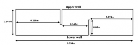
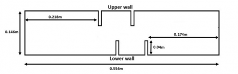
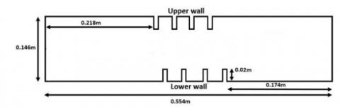
Figure 1 shows the 2-D duct configuration models as well as the exact dimensions of the vertical baffles at the upper and lower walls of the duct. The channel is 0.554 m long, 0.146 m high, and 0.193 m width. In these models, there are three different arrangements of the solid vertical baffles. Case (1) where there are only two vertical baffles; one is situated at the upper wall, 0.218 m from the duct inlet while the other is located at bottom wall, 0.174 m from the duct’s exit. The height and thickness of each baffle are 0.08, 0.01 m, respectively. The horizontal distance between the two baffles is 0.142 m. Case (2) where each baffle is replaced by two ones keeping the same distances from the channel’s boundaries with the first top baffle and second bottom baffle (i.e., 0.218 m & 0.174 m from the channel’s inlet and exit, respectively). The thickness of each baffle is unchanged (0.01 m). Each of the new two baffles has half height of the original baffle (i.e., 0.04 m). The horizontal distance between the two baffles that are mounted at the upper side of the channel is 0.095 m which is the same distance for the other two baffles located at the bottom surface. Case (3) by keeping the same approach. Each baffle in case (2) is replaced by two ones keeping the same dimensions from the channel’s boundaries with the first top baffle and last bottom one. Each of the four new baffles in case (3) has a height of 0.02 m (one fourth of the original baffle height). The horizontal distance between each successive baffles at the upper and lower walls is 0.0406 m. Keeping the thickness of each baffle as 0.01 m.
Case (1)
Case (2)
Case (3)
Figure 1. The channel's 2-D model with three cases under investigation
2.2 Numerical model
The simulations are executed with fixing flow rate, giving Reynolds number of 52,000, in order to understand the fluctuation of the velocity profile, temperature field, pressure drop, turbulent kinetic energy and skin friction coefficient along the channel.
The finite volume approach is used to numerically solve the governing equations and associated boundary conditions. Patankar [30] created the SIMPLE algorithm for processing velocity-pressure coupling. The governing equation's convection and diffusion terms are discretized using the center scheme and the QUICK scheme [31]. The latter is considered a higher order scheme.
The following presumptions are made in this study:
• Air's physical characteristics, i.e. the following are taken to be constants: dynamic viscosity, specific heat at constant pressure, density, and thermal conductivity.
• It is assumed that the air flow is incompressible, turbulent, and in a steady state.
• It is assumed that the velocity field at the channel's inlet section (at x=0) is uniform and 1-D (u=Uin) and the temperature is 300 K.
• At the channel outlet (at x=L), the atmospheric pressure (Patm) is the standard value.
• The upper wall’s temperature is kept constant at 375 K while the lower wall is insulated.
• All channel walls and baffles are subject to impermeable and non-slip boundary conditions.
• The radiation-induced heat transfer is disregarded.
• The simulations used in this research are steady state and incompressible.
The boundary conditions at the inlet, exit, and walls are described by the following equations with adiabatic baffles for all cases under study.
At inlet:
$T=300 \mathrm{~K}$ (17)
$u=U_{\text {in }}$ (18)
$v=0$ (19)
$k_{\text {in }}=0.005 U_{\text {in }}^2$ (20)
$\varepsilon_{\text {in }}=0.1 k_{\text {in }}^2$ (21)
At outlet:
$\frac{\partial u}{\partial x}=0$ (22)
$\frac{\partial v}{\partial x}=0$ (23)
$\frac{\partial k}{\partial x}=0$ (24)
$\frac{\partial \varepsilon}{\partial x}=0$ (25)
$P=P_{\mathrm{atm}}$ (26)
At walls:
$u=0$ (27)
$v=0$ (28)
$k=0$ (29)
$\varepsilon=0$ (30)
At upper wall:
$T=375 \mathrm{~K}$ (31)
At lower wall:
$Adiabatic$
2.3 Mesh study
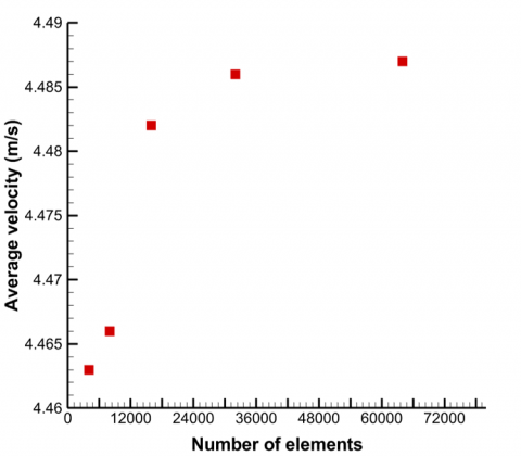
To compare the mesh independence and its impact on the outcome results, a mesh inspection was first completed. At x=0.36 m along the vertical axis and Re=52,000, the mesh study for the axial velocity is shown in Table 1.
This location, just prior to the second baffle, was specifically chosen because we expect significant variations in velocity profiles. The mesh dependence was examined by solving the flow domain for six (6) mesh arrangements with 2000, 4000, 8000, 16000, 32000, and 64000 cells, respectively.
Figure 2 shows the variations of maximum axial velocity at x=0.36 m vs the number of elements at Re=52000. As can be seen, 32000 elements were enough to simulate the system.
Table 1. The average axial velocity versus the number of elements for the mesh study at x=0.36 m along the vertical axis
|
Number of Elements |
Uavg |
|
2000 |
4.447 |
|
4000 |
4.463 |
|
8000 |
4.466 |
|
16000 |
4.482 |
|
32000 |
4.485 |
|
64000 |
4.487 |
Figure 2. Variations of average axial velocity at x=0.36 m vs the number of elements at Re=52000
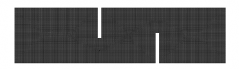
Figure 3. Mesh created from the inlet of the channel along the two vertical baffles to the exit, case (1), at 32000 elements
The mesh formed from the entry to the duct's outlet, via the two vertical baffle plates, is depicted in Figure 3.
2.4 Validation
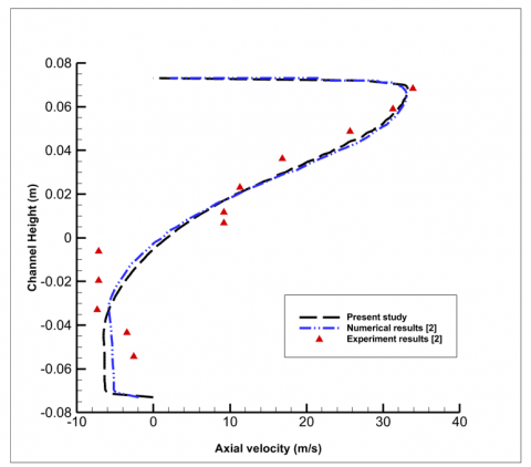
This code was validated before in one of our previous papers, Alwatban and Othman [1]. The CFD model results were validated by comparing them to experimental work conducted by Demartini et al. [2], who studied turbulent air flow in a rectangular channel with baffle plates. Our findings align closely with those of Demartini et al. [2] at x=0.525 m and Re=87300, as shown in Figure 4. This comparison demonstrates strong agreement between the current and past results, confirming the validity of our model.
To validate the code with another researcher, the output of the created CFD model was compared with Saha [23]. He investigated the turbulent fluid flow in a rectangular cross-section channel with two baffle plates that were positioned on opposite sides of the wall surfaces. The comparison between our results and Saha showed an excellent agreement. At Re=50000, the normalized friction factor (f/fo) and the thermal enhancement factor (TEF) were 40 and 1.4 while ours at Re=52000 are 37.7 and 1.27, respectively. The errors are 5.7% and 9.2%. As a result, this comparison validates our model.
Figure 4. Comparison between our results and Demartini et al. [2] at x=0.525 m and Re=87300
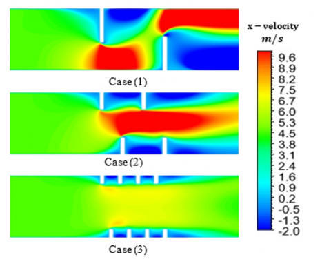
Understanding the dynamic behavior of these three configurations is necessary before the thermal aspect of cases calculated in this work is illustrated. It is well known that during the passage over a straightforward baffle plate, the flow splits at a principal zone known as the zone of reattachment, which is situated at the top of the baffle and experiences extremely high fluid particle speeds. This phenomenon is clearly visible in Figure 5 for case (1). The attachment zone exhibits a higher coefficient of the heat transfer as a result of the turbulence intensity and velocity fluctuations. The second zone, known as the secondary recirculation zone, is caused by the flow splitting at the baffle's edge and is situated behind the baffle. Because of the baffles introduced in the channel heat exchangers, the flow recirculation zone poses a significant challenge to the execution of the thermal transfer. On the other hand, for case (2), we found that the maximum velocities values are almost in the middle of the channel. In this case, the baffles act like a nozzle where flow area was reduced and, as a result, the velocity increases since the flow is assumed to be incompressible. Case (3) is almost the same behavior as case (2) but with less values of velocities. The recirculation areas were much less in size compared with cases (1 and 2).
Figure 5. Axial velocity field at Re= 52,000 for case (1), case (2), and case (3) along the channel
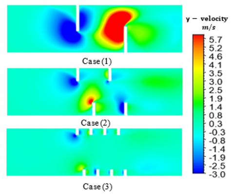
The vertical velocity scale makes it evident that some values are negative and others are positive as shown in Figure 6, case (1). It is commonly known that the currents flow in a positive direction toward the channel's upper sides. For instance, there are positive values in the flow through the second obstruction adjacent to its frontal areas. Additionally, the maximum values of vertical velocity are spread throughout the entire left section of the second baffle, particularly for currents with higher flow rates. However, because of the downward flow acceleration, the currents flowing through the first obstruction displayed negative values for the vertical velocity component, particularly in the opposite direction of the vertical axis. In case (2), the same behavior was recognized for the first pairs of baffles in the flow direction with much less size compared to case (1). On the other hand, negative values for the velocity vertical component was noticed ahead of the second baffle that is located at the bottom wall. Additionally, the maximum values of the vertical velocities were much less in case (3) compared with other cases. The velocity values close to the center of the channel are unchanged with no effect of the four baffles arrangements at the top and bottom sides of the channel.
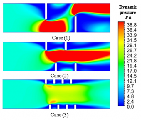
Through the analysis of the dynamic pressure fields, it becomes evident that, in the presence of evident friction with the hot surface, the main flow exhibits a periodic shape from left to right. Figure 7 demonstrates the field analysis that dynamic pressure was impacted by various obstruction models. For instance, increased dynamic pressure values are concentrated in a specific areas of the main stream, such as below top and above bottom baffles in case (1) and in the middle of the channel in case (2). On the other hand, the dynamic pressure completely decreased in the majority of the areas, particularly behind the obstacles, which led to the formation of vortices with varying intensities. The change in flow velocities, where it is evident that there is a direct proportion between the two parameters, also shows the influence of dynamic pressure values.
Figure 6. Vertical velocity field at Re=52,000 for case (1), case (2), and case (3) along the channel
Figure 7. Dynamic pressure field at Re=52,000 for case (1), case (2), and case (3) along the channel
There is an excellent agreement between the axial velocity and dynamic pressure fields. Both exhibits the same trend and behavior.
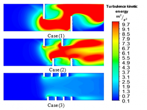
At three distinct baffles arrangements of heights 0.08, 0.04, and 0.02 m, Figure 8 depicts the turbulent kinetic energy contour of turbulence at Reynolds number of 52,000 along the channel. As can be observed, the baffles's recirculating flow enhances fluid mixing and moves heat from the heated wall into the duct's center. It was observed that some vortex flows increase the turbulent kinetic energy rate. One of the fundamental physical explanations for the improvement of the heat transfer in the presence of vortex generators is the intense kinetic energy beyond the leading edges of the turbulators. The intensity of the kinetic energy is almost the same for cases (1 and 2) although case (1) exhibits better behavior. The turbulence is less important and has an approximately constant value at upstream of the first baffle. Turbulent kinetic energy acheives its maximum value of approximately 9.7 m2/s2 for cases (1 and 2) and about 4.3 m2/s2 for case (3). The findings show that using shorter baffles significantly reduces the intensity of the kinetic energy.
Figure 8. Turbulent kinetic energy field at Re= 52,000 for case (1), case (2), and case (3) along the channel
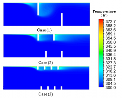
Figure 9. Temperature variation field at Re= 52,000 for case (1), case (2), and case (3) along the channel
Figure 9 shows the change in the temperature of the air passing over the duct. The top wall of the channel was kept at 375 K while the lower one and all baffles are considered to be insulated. It was noted that near the upper wall, and downstream of the upper baffle for case (1), there is a bigger zone of temperature gradient compared to cases (2 and 3). The presence of baffles significantly improves heat transfer. They augment mixing by the boundary layer separation in the duct, and this is the primary cause of the heat transfer enhancement in this system. The second reason is the continuous process of boundary layer growth and wake destruction. The temperature behavior matches very well with the axial velocity and dynamic pressure trends, Figures 4 and 6, respectively.
The summary of the results for three different heights of the baffles; 80,40, and 20 mm is presented in Table 2. It shows the variation of normalized Nusselt number, normalized friction coefficient and thermal enhancement factor at Re=52,000.
Table 2. Summary of the results for the three cases under study
|
Case |
Re |
Nu/Nuo |
f/fo |
Thermal Enhancement Factor (TEF) |
|
1) 80 mm |
52000 |
4.27 |
37.72 |
1.27 |
|
2) 40 mm |
52000 |
2.37 |
4.92 |
1.39 |
|
3) 20 mm |
52000 |
1.69 |
3.47 |
1.12 |
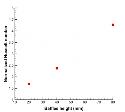
Figure 10 shows the variation of normalized Nusselt number. Its rate was significantly enhanced by increasing the baffle height, suggesting an increase in the energy exchange within the working fluid as a result. Case (1) arrangement improved the mixing of the working fluid and enhanced swirling of the fluid layers, it recorded the highest heat transfer rate.
Figure 10. Variation of normalized Nusselt number at Re=52,000 for different heights of the vertical baffles
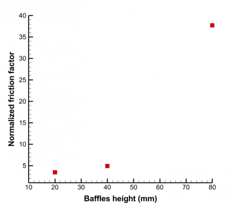
Figure 11 shows the normalized friction coefficient versus baffles configurations at constant Re of 52,000. The pressure drop rises as a result of the change in the heat transfer, which is connected to the friction coefficient consequence. It is due to weak zone's existence that allows the maximum values of friction to be reached in the zones behind each baffle. These values increase in an exponential way as the height of the baffle increases from 20 to 80 mm for the three cases under study. It is examined that the friction coefficient is insignificant upstream of the first baffle in the area preceding it.
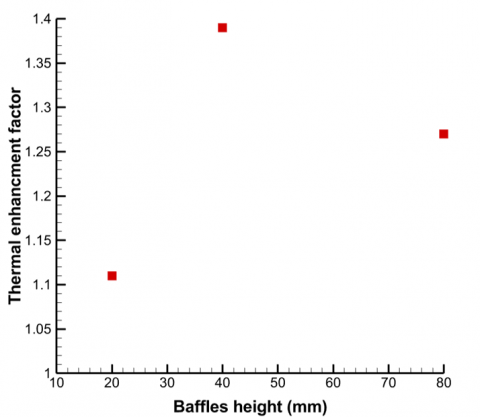
Figure 12 shows the variation of thermal enhancement factor (TEF). It is noticed that the maximum value of TEF occurred at the second case, two baffles at the top and bottom of the wall with 40 mm high each. Although the maximum rate of heat transfer was happened for case (1) but the friction value was also very high compared to the second case where an increase of about 767% of friction was calculated.
Based on our results, we recommend the second configuration among others.
It has been observed that as baffle height increases, so do the values of F, TEF, and Nu. However, the thermal enhancement factor reaches maximum value at baffle height of 40 mm then decreases while F and Nu continues the increasing trend. It has been noted that as the thermal gradient improves at peak velocity, the distance of the recirculation zone is increasingly important.
Figure 11. Variation of normalized friction coefficient at Re=52,000 for different heights of the vertical baffles
Figure 12. Variation of thermal enhancement factor at Re=52,000 for different heights of the vertical baffles
The optimal configuration of the three cases under study is one that maximizes the enhancement of heat. However, the findings revealed that higher heat transfer enhancement was linked to a rise in friction factor. This is due to the expansion of the secondary flow area, which not only boosts turbulence and fluid mixing but also leads to an increase in pressure drop. For example, case (1) shows the greatest increase in Nusselt number, but also experiences the highest growth in friction factor. Hence, determining the most effective configuration cannot rely solely on Nusselt number or friction factor enhancement. Consequently, it is essential to assess thermo-hydraulic performance, which considers both thermal enhancement and friction factor.
The primary focus of this study's numerical analysis is the flow characteristics and pressure distribution of turbulent fluid (air) flow over a rectangular channel equipped with three distinct configuration arrangements of solid vertical baffle plates. In this analysis, the finite volume method was used to solve the two-dimensional differential equations. The Fluent software implements the k-ε turbulence model, which resolves the turbulence dynamics. The entrance velocity field, the upper and lower walls' thermal conditions, and the exit atmospheric pressure, were altered as boundary conditions in order to thoroughly assess the system. The solid vertical baffles in the current model are arranged in three different ways. In case (1), there are just two vertical baffles; one is located at top and bottom channel walls, each has a height of 0.08 m. In case (2), there are two baffles in place of each baffle each has a height of 0.04 m. Using the same method, each baffle in case (2) is replaced by two new ones that have a height of 0.02 m, case (3).
Excellent comparability was demonstrated by the experimental data, which confirmed the validity of the model. Examining how these configurations affect turbulent kinetic energy, pressure drop, temperature variation, friction coefficient, velocity profile, and thermal enhancement factor is the aim of the study. At 52,000, the Reynolds number is maintained constant.
The main findings derived from the present study are as follows: (i) mixing can be enhanced by adding vertical baffles. In case (1), maximum axial velocities are reached in the middle of the channel; in case (2), they are reached above and below the top and bottom baffles. There exist multiple recirculation zones visible at strategic locations, such as behind, above, and below the baffles. (ii) Case (2) attained a thermal enhancement factor maximum of 1.39, while it was 1.27 and 1.12 for case (1) and case (3), respectively. Thus, four vertical solid baffles of 0.04 m in height are used to optimize this system; two of them are positioned at the top and bottom walls of the channel. (iii) Various obstruction models had an impact on dynamic pressure. For example, increased dynamic pressure values were found to be concentrated in specific areas of the main stream, such as below top and above bottom baffles in case (1) and in the middle of the channel in case (2). Conversely, dynamic pressure decreased significantly in most areas, especially behind the obstacles, resulting in the creation of vortices with different strengths. The alteration in flow velocities, which indicates a direct relationship between the two factors, also reflects the influence of dynamic pressure values. (iv) The change in normalized Nusselt number was observed when the baffle height was increased as 4.27, 2.37, and 1.69 for cases (1,2 and 3), respectively. This indicates a rise in energy exchange within the working fluid. The configuration in Case (1) led to better mixing of the working fluid and increased swirling of the fluid layers, resulting in the highest heat transfer rate recorded.
Lastly, based on the results of the current numerical simulation analysis, a number of further research in the future needs to be considered. These consist of the following, but are not restricted to them. (1) Modify the shape of the baffles by using angled baffles rather than straight ones. (2) Change the dimensions between the baffles and/or adding more baffles. (3) Change the Reynolds number values to cover extended ranges of inlet velocities. (4) Examine different thermal conditions at the top and bottom walls of the channel.
|
u |
fluid velocity in x-direction; m/s |
|
v |
fluid velocity in y-direction; m/s |
|
ρ |
density; kg/m3 |
|
P |
static pressure; Pa |
|
$\mu_l$ |
molecular viscosity; Pa.s |
|
$\mu_t$ |
turbulent viscosity; Pa.s |
|
$\tau_w$ |
shear stress at the wall; N/m2 |
|
$c_\mu$ |
turbulent constant |
|
$\sigma_k$ |
turbulent constant |
|
$\varepsilon_k$ |
turbulent constant |
|
$G_{1 \varepsilon}$ |
turbulent constant |
|
$G_{2 \varepsilon}$ |
turbulent constant |
|
Cf |
skin friction coefficient |
|
$D_h$ |
hydraulic diameter; m |
|
H |
height of the channel; m |
|
W |
width of the channel; m |
|
$\Delta P$ |
pressure drop; Pa |
|
$N u_x$ |
local Nusselt number |
|
$h_x$ |
convection heat transfer coefficient; W/m2K |
|
$k_f$ |
thermal conductivity; W/mK |
|
Pr |
Prandtl number |
|
Re |
Reynolds number |
|
TEF |
Thermal Enhancement Factor |
[1] Alwatban, A., Othman, H. (2023). Numerical analysis of turbulent air flow dynamics in a rectangular channel with perforated nozzle-shaped vertical baffles. International Journal of Heat & Technology, 41(6): 1407-1416, https://doi.org/10.18280/ijht.410602
[2] Demartini, L.C., Vielmo, H.A., Möller, S.V. (2004). Numeric and experimental analysis of the turbulent flow through a channel with baffle plates. Journal of the Brazilian Society of Mechanical Sciences and Engineering, 26: 153-159. https://doi.org/10.1590/s1678-58782004000200006
[3] Khoshvaght-Aliabadi, M., Hormozi, F., Zamzamian, A. (2014). Experimental analysis of thermal–hydraulic performance of copper–water nanofluid flow in different plate-fin channels. Experimental Thermal and Fluid Science, 52: 248-258. https://doi.org/10.1016/j.expthermflusci.2013.09.018
[4] Khoshvaght-Aliabadi, M., Hormozi, F., Zamzamian, A. (2014). Role of channel shape on performance of plate-fin heat exchangers: Experimental assessment. International Journal of Thermal Sciences, 79: 183-193. https://doi.org/10.1016/j.ijthermalsci.2014.01.004
[5] Ahmed, H.E., Mohammed, H.A., Yusoff, M.Z. (2012). Heat transfer enhancement of laminar nanofluids flow in a triangular duct using vortex generator. Superlattices and Microstructures, 52(3): 398-415. https://doi.org/10.1016/j.spmi.2012.05.023
[6] Bhuiyan, A.A., Islam, A.S. (2016). Thermal and hydraulic performance of finned-tube heat exchangers under different flow ranges: A review on modeling and experiment. International Journal of Heat and Mass Transfer, 101: 38-59. https://doi.org/10.1016/j.ijheatmasstransfer.2016.05.022
[7] Benzenine, H., Saim, R., Abboudi, S., Imine, O. (2013). Numerical analysis of a turbulent flow in a channel provided with transversal waved baffles. Thermal Science, 17(3): 801-812. https://doi.org/10.2298/tsci111004099b
[8] Jamil, M.M., Adamu, M.I., Ibrahim, T.R., Hashim, G.A. (2015). Numerical study of separation length of flow through rectangular channel with baffle plates. Journal of Advanced Research Design, 7(1): 19-33.
[9] Benosman, F., Amraoui, M.A. (2021). Study of air flow in a solar collector equipped with two inclined obstacles. In E3S Web of Conferences, Paris, France, p. 04015. https://doi.org/10.1051/e3sconf/202132104015
[10] Menni, Y., Lorenzini, G., Kumar, R., Mosavati, B., Nekoonam, S. (2021). Aerodynamic fields inside S-shaped baffled-channel air-heat exchangers. Mathematical Problems in Engineering, 2021: 1-11. https://doi.org/10.1155/2021/6648403
[11] Salmi, M., Afif, B., Akgul, A., Jarrar, R., Shanak, H., Menni, Y., Asad, J. (2022). Turbulent flows around rectangular and triangular turbulators in baffled channels: A computational analysis. Thermal Science, 26(1): S191-S199. https://doi.org/10.2298/TSCI22S1191S
[12] Mahdi, K., Bekrentchir, K., Hussein, A.K., Akgul, A., Shanak, H., Asad, J., Menni, Y. (2022). Using obstacle perforation, reconfiguration, and inclination techniques to enhance the dynamic and thermal structure of a top-entry channel. Thermal Science, 26(1): S475-S484.
[13] Menni, Y., Ghazvini, M., Ameur, H., Kim, M., Ahmadi, M.H., Sharifpur, M. (2020). Combination of baffling technique and high-thermal conductivity fluids to enhance the overall performances of solar channels. Engineering with Computers, 38: 607-628. https://doi.org/10.1007/s00366-020-01165-x
[14] Boonloi, A., Jedsadaratanachai, W. (2021). Heat transfer potentiality and flow behavior in a square duct fitted with double-inclined baffles: A numerical analysis. Modelling and Simulation in Engineering, 2021: 1-15. https://doi.org/10.1155/2021/9957126
[15] Razavi, S.E., Adibi, T., Faramarzi, S. (2020). Impact of inclined and perforated baffles on the laminar thermo-flow behavior in rectangular channels. SN Applied Sciences, 2(2): 284. https://doi.org/10.1007/s42452-020-2078-8
[16] Menni, Y., Azzi, A., Chamkha, A., Harmand, S. (2019). Analysis of fluid dynamics and heat transfer in a rectangular duct with staggered baffles. Journal of Applied and Computational Mechanics, 5(2): 231-248. https://doi.org/10.22055/JACM.2018.26023.1305
[17] Ameur, H., Sahel, D., Menni, Y. (2021). Numerical investigation of the performance of perforated baffles in a plate-fin heat exchanger. Thermal Science, 25(5 Part B): 3629-3641. https://doi.org/10.2298/TSCI190316090A
[18] Liang, C.H., Feng, C.N., Lei, T.Y., Li, Z.X. (2019). Numerical studies on the effect of baffle on the heat transfer and flow in cross-corrugated triangular ducts. In IOP Conference Series: Earth and Environmental Science, Hong Kong, p. 012086. https://doi.org/10.1088/1755-1315/238/1/012086
[19] Putra, A.B.K., Ahn, S.W. (2008). Heat transfer and friction behaviour in a channel with an inclined perforated baffle. International Journal of Air-Conditioning and Refrigeration, 16(2): 70-76.
[20] Ameur, H. (2020). Effect of corrugated baffles on the flow and thermal fields in a channel heat exchanger. Journal of Applied and Computational Mechanics, 6(2): 209-218. https://doi.org/10.22055/JACM.2019.28936.1521
[21] Dutta, P., Dutta, S. (1998). Effect of baffle size, perforation, and orientation on internal heat transfer enhancement. International Journal of Heat and Mass Transfer, 41(19): 3005-3013. https://doi.org/10.1016/S0017-9310(98)00016-7
[22] Eiamsa-ard, S., Pattanapipat, S., Promvonge, P. (2013). Influence of triangular wavy baffles on heat and fluid flow characteristics in a channel. Journal of Mechanical Science and Technology, 27: 2199-2208. https://doi.org/10.1007/S12206-013-0534-8
[23] Saha, S. (2021). Numerical study of air-flow phenomena through a baffled rectangular micro-channel. Journal of Modeling and Optimization, 13(2): 51-57. https://doi.org/10.32732/jmo.2021.13.2.51
[24] Liu, H.L., Guo, H.Y., Xie, Z.L., Sang, L. (2021). Numerical investigations for optimizing a novel micro-channel sink with perforated baffles and perforated walls. International Communications in Heat and Mass Transfer, 126: 105342. https://doi.org/10.1016/j.icheatmasstransfer.2021.105342
[25] Nakhchi, M.E., Hatami, M., Rahmati, M. (2021). Experimental investigation of performance improvement of double-pipe heat exchangers with novel perforated elliptic turbulators. International Journal of Thermal Sciences, 168: 107057. https://doi.org/10.1016/j.ijthermalsci.2021.107057
[26] Karabulut, K. (2024). Heat transfer and thermal–hydraulic evaluations of cross-circular grooved rectangular flow ducts depending on rectangular baffle design parameters. The European Physical Journal Plus, 139(3): 227. https://doi.org/10.1140/epjp/s13360-024-05003-7
[27] Samruaisin, P., Maza, R., Thianpong, C., Chuwattanakul, V., Maruyama, N., Hirota, M., Eiamsa-ard, S. (2023). Enhanced heat transfer of a heat exchanger tube installed with v-shaped delta-wing baffle turbulators. Energies, 16(13): 5237. https://doi.org/10.3390/ en1613523
[28] Xi, Y., Meng, F. (2024). Numerical study on flow and heat transfer characteristics of rectangular mini-channel of interpolated double S turbulators. Plos One, 19(2): e0297678. https://doi.org/10.1371/journal.pone.0297678
[29] Reddy, P.N., Verma, V., Kumar, A., Awasthi, M.K. (2023). CFD simulation and thermal performance optimization of channel flow with multiple baffles. Journal of Heat and Mass Transfer Research, 10(2): 257-268. https://doi.org/10.22075/JHMTR.2023.31108.1458
[30] Patankar, S.V. (1980). Numerical heat transfer and fluid flow. Series in Computational Methods in Mechanics and Germal Sciences, Hemisphere Publishing Corporation, New York, NY, USA.
[31] Boonloi, A., Jedsadaratanachai, W. (2019). Numerical study on flow and heat transfer mechanisms in the heat exchanger channel with V-orifice at various blockage ratios, gap spacing ratios, and flow directions. Modelling and Simulation in Engineering, 2019: 061102. https://doi.org/10.1155/2019/8656435