Sarah Rabeea Nashee![]()
© 2024 The author. This article is published by IIETA and is licensed under the CC BY 4.0 license (http://creativecommons.org/licenses/by/4.0/).
OPEN ACCESS
This study presents a comprehensive analysis of laminar convective heat transfer in water-based Titanium Dioxide (TiO2) nanofluids flowing through 90° elbow joints with distinct cross-sectional geometries. Employing computational fluid dynamics (CFD) simulations via ANSYS Fluent, the investigation encompasses Reynolds numbers ranging from 100 to 900 and nanoparticle volume fractions extending from 0.00 to 0.04. The focus is on three elbow joints, each characterized by a unique cross-sectional shape – circular, triangular, and square – while maintaining identical cross-sectional areas (0.636 m²) and curvature radii (165 mm). The study conducts these simulations under a consistent heat flux condition to evaluate thermal performance. The results demonstrate a marked superiority of the triangular cross-section in enhancing heat transfer efficiency across all tested velocities, followed by square and circular geometries, respectively. This finding reveals the significant impact of elbow cross-sectional shape on heat transfer in nanofluid flows. Furthermore, a comparative analysis with relevant previous studies validates the consistency and reliability of the current findings.
nano-fluid, elbow, heat transfer, fluid flow, pressure drop
Lately, the analysis of the transfer of heat and energy in the pipeline elements, such as the elbow, orifice, and tee junction, as basic devices in many thermal plants, has been an effective topic. In order for the devices to be sufficient instruments in the industrialization of power plants, authors and researchers have investigated them [1, 2]. To apply and design in this field, the use of bends in channels is necessary. The turns of pipes have a large pressure drop value compared to straight pipes; this behavior is caused by changes in trajectory and geometry that result in changes in the patterns of the flow. The value of the pressure drop can be found by choosing the bend angle [3]. Nanofabrication developments have led researchers to produce particles at the nanometer scale. These particles were added to the working fluid, and that has led to new fluids called ‘nanofluids’ [4]. The nanofluids could be employed for cooling electronic applications [5]. The presence of nanoparticles has a special character, which makes the fluid capable of being influenced by various applications as a magnetic field [6]. Most of the time, optimizing heat transfer systems works by raising their level, which usually leads to raising volume and size. So to avoid this, several new systems are presented, and nanofluid is considered a new method. The new technology to deal with particles in nanometer dimensions was enhanced, and a new type of solid-liquid mixture called nanofluid appeared [7, 8]. Scientific experiments on elbow pipes gradually developed, and the literature reviews show some research that focused on testing and improving the flow, as well as the effect of pressure and velocity and their characteristics on the flow of fluids in those elbows. Experimentally, Kawamura et al. [9] estimated various conditions to test the flow in several elbow pipes. measured turbulence intensity and velocity field in a 90° elbow, (r/D)=0.55, 1 and 2 at the range of Re=5×10⁴ and 5×10⁵ employing LDV measurement. The results gave important information about the turbulent intensity, the impact of Re and the unsteady flow structure formed by the separation and the secondary flow. Crawford et al. [10] conducted a test with an elbow with turbulent single-phase fluid flow around a sharp 90° and bends with a ratio of R/r<2. The Reynolds number ranged from 4×10³ to 3×10⁵. Results found that the pressure loss was due to frictional effects. Also, according to tests on the impact of employing nanoparticles, Yang et al. [11] performed a study to test the effect of the behavior of nanoparticle fractions suspended in working fluid, employing water-TiO2 for laminar flow with (Re) varying from 500-2000. A comparison between straight tubes and bent tubes has been performed. These results reported that high values of fraction nanoparticles can be maintained for nanofluids at greater (Re) and fewer elbows. Also, Korei and Benissaad [12] conducted a numerical analysis by using forced convection of an Al2O3-water through a (3D) 90° elbow. The simulation parameters included different (Re) values of 10,000-100,000, with nanoparticle volume fractions ranging from 2% to 6%. In this elbow, the results reported that the pressure drop rises with the volume fraction increasing. Tony and Tsai [13] carried out a simulation of incompressible flow in a square channel with a 90-degree bend and a curvature radius (R) of 2.3. The tests have been done for the flow at Re=790. The simulated results showed secondary flow in the curved channel.
FurtA simulation using fluid had been conducted by Farsani and Nodooshan [14] for force convection heat transfer of turbulent flow in 90- and 60-degree elbows. The working nanofluids are Al2O3 and water. The results have shown that by increasing the Reynolds number and concentration of nano, heat transfer increases in value and the friction coefficient falls. The elbow is compared, and the results obtained reported that by raising the angle of bending of the elbow, heat transfer values decreased. Ebrahimi and Niazmand [15] conducted numerical investigations for the laminar flow of water with carbon nanotubes in a 90-degree) curved pipe (elbow). The experiments indicated that, up to the secondary flows caused by the effects of curvature, the heat transfer rate is clearly enhanced, further employing nanofluids.
On the other hand, Safaei et al. [16] conducted a study dealing with erosion prediction at 90° elbow for turbulent flow. For nanofluid with a range of particle sizes from 10 nm to 100 microns of carbon and volume fractions ranging from 0.00 to 0.04, the simulation was performed for a velocity range of 5-20 m/s. The works indicate that the erosion rate is dependent on volume fraction and particles’ size. In this current work, a simulation of nanofluid (TiO2 as a nanoparticle and water as a base fluid) with three identical cross-sections of elbows (circular, triangular, and square) with 90 degrees of bending has been conducted. The heat transfer rate and the effect of the presence of nanofluid on the flow. Moreover, comparisons among the three elbow’s cases are performed, and another is made with the recent searches.
2.1 Model description
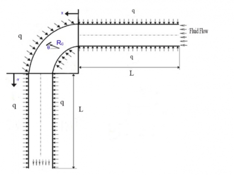
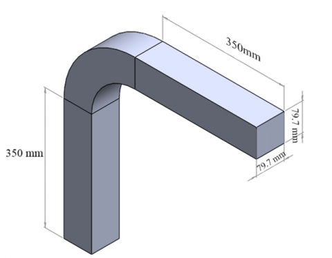
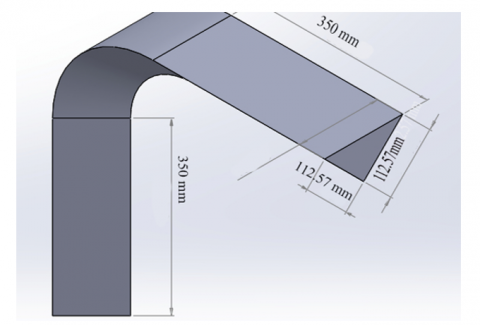
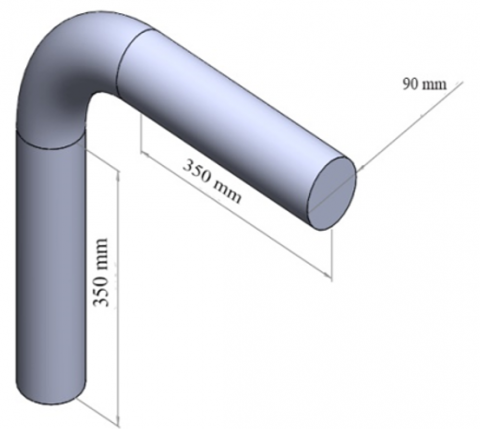
The geometry of a typical elbow is designed in 90-degree bending with three cases of identical cross-sections (circular, triangular, and square). The cross-section of all cases is 0.636 m2, and the curvature of bending is 158 mm for all cases. The working fluid is TiO2-H2O for three volume fractions of 0.00, 0.02, and 0.04. The nanoparticles volume is 75 nm. Table 1 displays the physical properties of the working fluid. The elbow is under uniform heat flux, and the temperature of the inlet fluid is 300K. The tests of this work take a specific range of the fluid’s velocity and select the Reynolds number as a base that represents the velocity (Re) values of 100-300, 500-700-900). Figure 1 shows clearly the details of the elbow geometry. Figure 2 shows schematic diagram of the elbows.
Table 1. Thermo-physical properties of base fluid water (H2O) and solid nanoparticles (TiO2)
|
Material |
$\rho$ (kg/m3) |
Cp(J/kg K) |
k(W/m K) |
|
Pure water |
997.1 |
4179 |
0.613 |
|
TiO2 |
4050 |
683 |
1.134 |
2.2 Mesh generation grid independency
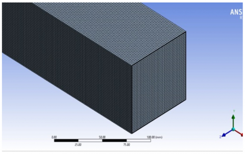
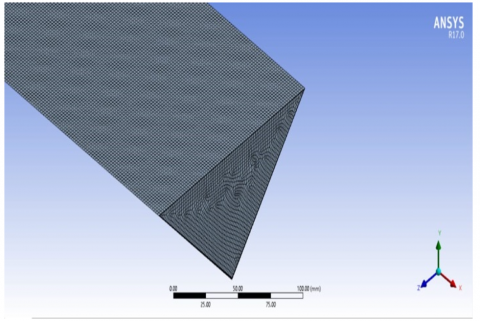
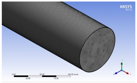
The CFD models were run successfully in all the tested cases. The non-uniform structured grid at Re=500 is displayed in Figure 3. Mish was created to discretize the computational region. Near the surface, due to the great gradient of temperature and velocity, the grid is considered very minimal. Discretization in space requires that the flow field be divided into small control volumes. Different types of control volumes are possible, including hexahedral and tetrahedral control volumes and structured or unstructured grids. The tetrahedral mesh is used because it is good for the separation flow. The number of elements for a circle is 1,254,798; 1,224,000 for a square; and 1,295,400 for a triangle. The grid independence test was conducted at Re=500 to determine the Nusselt number. In the grid independence test, the number of grids was increased until the difference in results between two consecutive grid sizes became negligible. The results are summarized in Table 2, which shows the specified grid for the three cases.
Figure 1. Two dimensional diagram
(a) Square cross-section elbow
(b) Triangular cross-section elbow
(c) Circular cross-section elbow
Figure 2. Schematic diagram of the elbow geometry
Figure 3. Mish generation for square, triangle and circle elbows
Table 2. Tested grids for the studied cases for Re=500, φ=4%
|
Cases |
Number of Element |
Nu |
|
Circular |
1,102,546 |
14.442 |
|
1,114,440 |
15.131 |
|
|
1,152,334 |
16.312 |
|
|
1,254,798 |
16.334 |
|
|
Square |
1,124,343 |
15.456 |
|
1,166,545 |
17.322 |
|
|
1,219,668 |
18.723 |
|
|
1,224,000 |
18.754 |
|
|
Triangular |
1,124,527 |
18.787 |
|
1,176,543 |
20.454 |
|
|
1,243,457 |
21.982 |
|
|
1,295,400 |
22.122 |
2.3 Governing equations
Turbulent flow is one of the most complicated kinds of flow. To analyze turbulent flow, a continuity equation, a Navier-Stokes equation, and an energy equation are used [17].
Equation of continuity:
$\frac{\partial u}{\partial x}+\frac{\partial v}{\partial y}=0$ (1)
x component of conservation of momentum:
$u \frac{\partial u}{\partial x}+v \frac{\partial u}{\partial y}+w \frac{\partial u}{\partial z}=-\frac{1}{\rho} \frac{\partial P}{\partial x}+\frac{\mu}{\rho}\left(\frac{\partial^2 u}{\partial x^2}+\frac{\partial^2 u}{\partial y^2}\right)$ (2)
y component of conservation of momentum:
$u \frac{\partial v}{\partial x}+v \frac{\partial v}{\partial y}+w \frac{\partial w}{\partial z}=-\frac{1}{\rho} \frac{\partial P}{\partial y}+\frac{\mu}{\rho}\left(\frac{\partial^2 v}{\partial x^2}+\frac{\partial^2 v}{\partial y^2}\right)$ (3)
z component of conservation of momentum:
$u \frac{\partial w}{\partial x}+v \frac{\partial w}{\partial y}+w \frac{\partial w}{\partial z}=-\frac{1}{\rho} \frac{\partial P}{\partial z}+\frac{\mu}{\rho}\left(\frac{\partial^2 w}{\partial x^2}+\frac{\partial^2 w}{\partial y^2}+\frac{\partial^2 w}{\partial z^2}\right)$ (4)
Energy equation [17]:
$u \frac{\partial T}{\partial x}+v \frac{\partial T}{\partial y}=\alpha\left(\frac{\partial^2 T}{\partial x^2}+\frac{\partial^2 T}{\partial y^2}\right)$ (5)
In this part, we ensure we have all the right equations to determine the variables.
The entrance velocity is calculated using formulas derived from the Reynolds number (Re), which serves as a measure of velocity [18].
$R e=\rho \mathrm{u}_{\mathrm{avg} .} D_h / \mu$ (6)
The net heat input to the fluid is defined as [19]:
$\mathrm{Q}=m^O \mathrm{C}_{\mathrm{p}}\left(T_o-T_i\right)$ (7)
($\overline{\mathbf{h}}$) is determined by formula [20]:
$\overline{\mathrm{h}}=\frac{Q}{A_s\left(T_w-T_b\right)}$ (8)
If the average wall temperature is reached by [20]:
$\mathrm{T}_{\mathrm{w}}=\frac{1}{n} \sum T_{w n}$ (9)
Twn is the local temperature along the channel walls.
The mean bulk temperature (Tb) is attained by the following formula [18]:
$T_b=\frac{\int_0^L \int_0^{\mathrm{H}} \int_0^W \rho\, c_p \,u T \,d x \,d y \,d z}{\int_0^{\mathrm{L}} \int_0^{\mathrm{H}} \int_0^W \rho\, u \,d x \,d y\, d z}$ (10)
The Nusselt number (Nu), a critical parameter in heat transfer analysis, represents the ratio of convective to conductive heat transfer at a boundary, its values can be estimated by formula [17]:
$N u=\frac{\bar{h} . D_h}{k}$ (11)
The overall performance factor (η) [20] is:
$\eta=\left(\mathrm{Nu} / \mathrm{Nu}_{\mathrm{o}}\right) /\left(\mathrm{f} / \mathrm{f}_{\mathrm{o}}\right) 1 / 3$ (12)
2.4 Boundary condition
In order to obtain a suitable solution to a partial differential equation, several additional conditions are necessary. A constant heat flux.
The boundary conditions of the temperature for the pipe inlet flows are constant and spatially uniform in time. Boundary conditions on the wall are set as adiabatic for the temperature and no-slip conditions for the velocity (w=v=0).
The fluid flow is in a steady state (no change in velocity with time), which was applied in the fluen ANSYS to simulate the flow.
As a comparison between volume fractions of 4 and 0, the results reported that φ=4 is greater than φ=0 by 16% and about 9% as compared with φ=2.
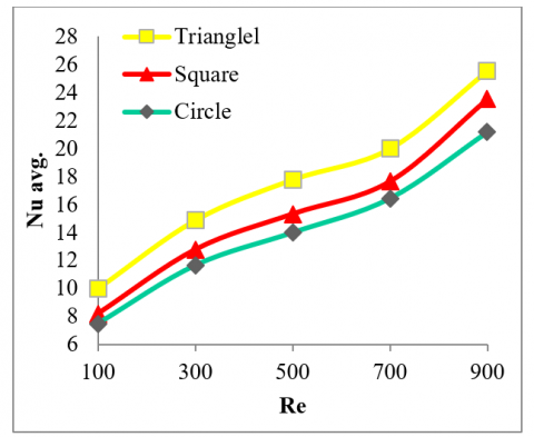
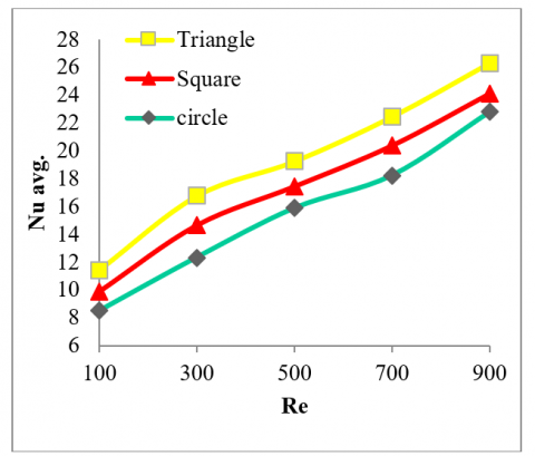
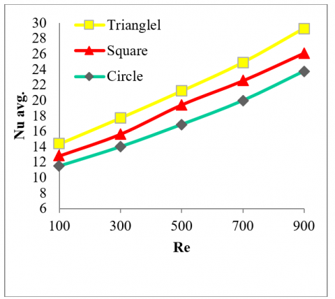
According to the comparisons between the cross-sections, the triangular gives the greater heat transfer at all volume fractions that testes. as compared with square and circular cases. Due to the more mixing of fluid between the hot surfaces and fluid,
The triangular case gives the peak intensification in the Nusselt number at 4% volume fraction, as contrasted with the other cases. The increase is about 8% for the square cases and 16% for the circular cases. Figure 4(a)-4(c) displays, in detail, the values of Nu.
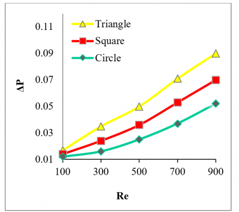
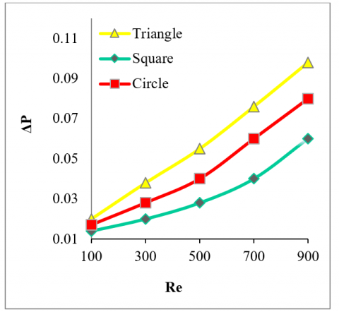
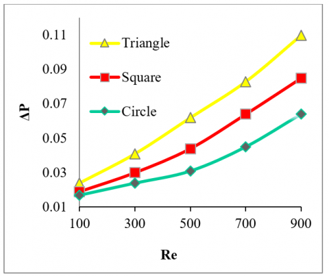
On the other hand. for the pressure drop. Figure 5 shows the clear difference in the results of the pressure drop between the three cases. The triangle gives the highest pressure compared to the square and circle for all volume fraction values. And the volume fraction of 4% gives the greatest value of pressure drop due to the fact that by raising the volume ratio of particles, the density increases, and thus the pressure drop becomes greater too.
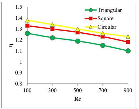
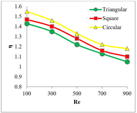
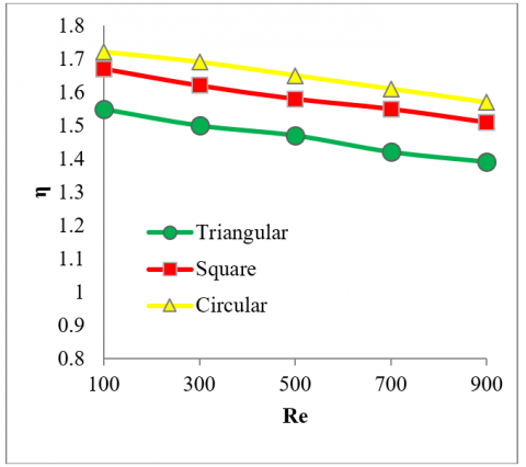
As for overall performance, Figure 6 demonstrated the performance for all the tested values of (Re). As displayed, the performance reduces slightly with increasing (Re). The result gives a maximum enhancement of 172%, 167%, and 153 for triangular, square, and circular, respectively, at Re=100 and a volume fraction of 4%.
The reason that the case of triangular cross-section gives the best overall performance as compared with square and circular for all values of volume fraction is It's due to the better turbulence given to water nanoparticles in the triangular case. It helped to increase the heat transfer between the flowing fluid and the surface of the elbow. While the case of circular gives the minimum values of overall performance.
(a) Variation of Nusselt number at φ=0%
(b) Variation of Nusselt number at φ=2%
(c) Variation of Nusselt number at φ=4%
Figure 4. Variation of Nusselt number with Re for triangle, square and circle for φ=0, 2 and 4%
(a) Variation of pressure drop at φ=0%
(b) Variation of pressure drop at φ=2%
(c) Variation of pressure drop at φ=4%
Figure 5. Variation of pressure drop with Reynold numbers for triangle, square and circle for φ=0, 2 and 4%
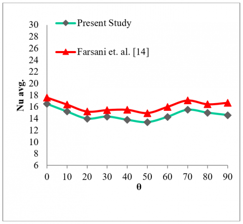
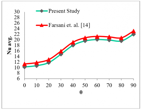
By comparison, the results of the local Nu of the inner and outer walls of the elbow pipe between the current study and Farsani et al. [14] at Re=500 and 4% fraction volume. We note the behavior of the inner and outer walls separately at different angles. The obtained data gives a deviation in the results between the two studies of 9% for the outer wall and 13% for the inner wall. As displayed in Figures 7 and 8.
(a) The overall performance φ=0%
(b) The overall performance φ=2%
(c) The overall performance φ=4%
Figure 6. The overall performance for triangular, square and circular at various Reynolds number (Re) and φ= 0, 2 and 4%
Figure 7. The local Nusselt number on the inner wall of the elbow in φ = 4%, Re=500
Figure 8. The local Nusselt number on the outer wall of the elbow in φ=4%, Re=500
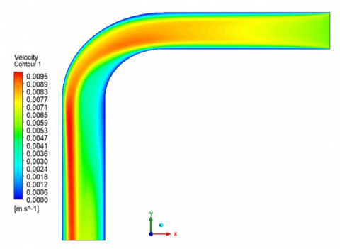
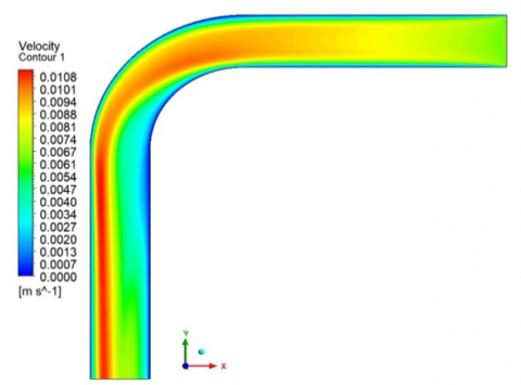
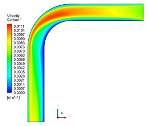
Figure 9 represents the differences in instantaneous velocity in the flow through the elbow pipe for the three cases. The profile for velocity at the inlet before the elbow region is clearly established. After that, when the nanofluid reaches downstream, the greatest velocity layer of nanofluid transfers towards the surfaces.
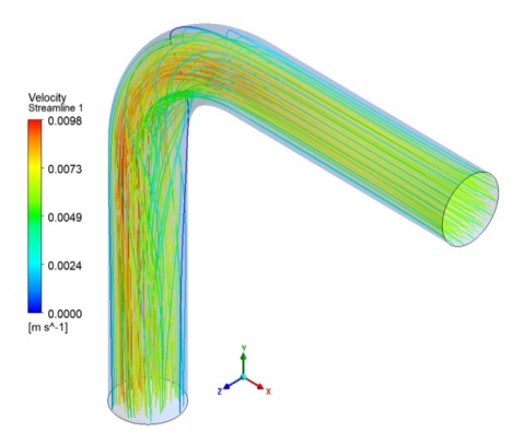
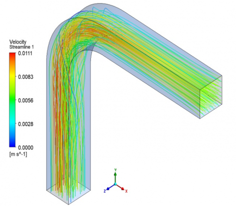
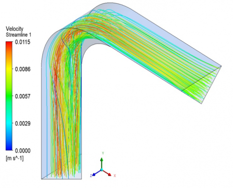
On the other hand, Figure 10 represents a clear vision of the velocity stream. The velocity is raising gradually towards the pipe's surface. After that, as a result of changing the shape of the flow stream, an irregularity and instability of the flow appear at the elbow area, and this appears clearly in the three cases. Moreover, the flow near the outlet shows an even distribution for the velocity. This behavior appears clearly in the triangular case. The reason the nano-fluid flow rate and heat transfer results are rising in the triangular case can be attributed to the cute angles of the triangular; they can induce a greater recirculation zone, hence enhancing the rate of heat transfer.
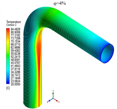
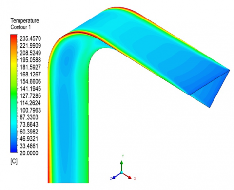
Figure 11 deals with the temperature variation along with the domain. This variation in temperature distribution was captioned for the three cases separately for airflow with (Re)=500 and fraction=4%. As represented, the fluid temperature reduces progressively from the outer of the pipe surfaces to its inner due to the absence of circulation flow. The figures (a, b, and c) show the influence of the cross section of flow on the temperature distribution. This difference reorganizes the temperature distribution. In the triangular case, there is a rise in flow mixing, where the range of temperature gradient increases in the triangular case, followed by the square case, and then the circular case.
(a) Velocity contour of circular elbow
(b) Velocity contour of square elbow
(c) Velocity contour of triangular elbow
Figure 9. Velocity contour of the three cases at Re=500, φ=4%
(a) Velocity stream line of circular elbow
(b) Velocity stream line of square elbow
(c) Velocity stream line of triangular elbow
Figure 10. Velocity stream line of the three cases at Re=500, φ=4%
(a) Temperature contour of circular elbow
(b) Temperature contour of square elbow
(c) Temperature contour of triangular elbow
Figure 11. Temperature contour of the three cases at Re=500, φ=4%
Several key findings have emerged from this investigation:
It was observed that the triangular cross-section exhibited superior heat transfer capabilities. This was evidenced by the highest Nusselt number values across all tested Reynolds number scenarios, followed by square, and then circular cross-sections.
In terms of nanoparticle volume fractions, a 4% concentration demonstrated the most significant enhancement in the Nusselt number. It was noted that the Nusselt number increased proportionally with the Reynolds number. This phenomenon can be attributed to the expanded surface areas of microparticles, which in turn enhance the heat transfer mechanisms.
However, this expansion of surface area concurrently elevates the conductive heat transfer within the nanofluid. As a consequence, there is a resultant increase in both the viscosity and density of the nanofluid, leading to an escalated pressure drop. Notably, the triangular configuration yielded the maximum pressure drop value at a Reynolds number of 900.
This study contributes to the understanding of the complex interplay between cross-sectional geometry, nanoparticle concentration, and fluid dynamics in heat transfer systems. The insights gained here have potential applications in optimizing industrial heat transfer processes, particularly in the context of nanofluid flow through varied geometries.
|
A |
Area/m2 |
|
Cp |
Heat capacity/ J kg-1 K-1 |
|
Dh |
Hydraulic diameter m |
|
H |
Microchannel height/m |
|
k |
Thermal conductivity coefficient/ Wm-1 K-1 |
|
L |
Inlet microchannel length, Outlet microchannel length / m |
|
q |
Surface heat flux/ W m-2 |
|
Nu |
Nusselt number |
|
P |
Fluid pressure/ Pa |
|
Re |
Reynolds number |
|
T |
Temperature/ K |
|
U, V |
Dimensionless velocity components in x, y directions |
|
X, Y |
Cartesian dimensionless coordinates |
|
u, v |
Velocity components in x, y directions/ ms-1 |
|
Greek symbols |
|
|
φ |
Nanoparticles volume fraction |
|
µ |
Dynamic viscosity/ Pa. s |
|
ρ |
Density/ kg. m-3 |
|
Subscripts |
|
|
b |
Bulk |
|
o |
With out Nanoparticles |
[1] Sheikholeslami, M., Gerdroodbary, M.B., Mousavi, S. V., Ganji, D.D., Moradi, R. (2018). Heat transfer enhancement of ferrofluid inside an 90° elbow channel by non-uniform magnetic field. Journal of Magnetism and Magnetic Materials, 460: 302-311. https://doi.org/10.1016/j.jmmm.2018.03.070
[2] Mokhtari, M., Gerdroodbary, M.B., Yeganeh, R., Fallah, K. (2017). Numerical study of mixed convection heat transfer of various fin arrangements in a horizontal channel. Engineering Science and Technology, an International Journal, 20(3): 1106-1114. https://doi.org/10.1016/j.jestch.2016.12.007
[3] Spedding, P.L., Bénard, E., Crawford, N.M. (2008). Fluid flow through a vertical to horizontal 90° elbow bend III three phase flow. Experimental Thermal and Fluid Science, 32(3): 827-843. https://doi.org/10.1016/j.expthermflusci.2007.10.002
[4] Sheikholeslami, M., Ashorynejad, H.R., Rana, P. (2016). Lattice Boltzmann simulation of nanofluid heat transfer enhancement and entropy generation. Journal of Molecular Liquids, 214: 86-95. https://doi.org/10.1016/j.molliq.2015.11.052
[5] Sheikholeslami, M., Ganji, D.D., Javed, M.Y., Ellahi, R. (2015). Effect of thermal radiation on magnetohydrodynamics nanofluid flow and heat transfer by means of two phase model. Journal of Magnetism and Magnetic Materials, 374: 36-43. https://doi.org/10.1016/j.jmmm.2014.08.021
[6] Sheikholeslami, M., Ganji, D.D. (2018). Influence of electric field on Fe3O4-water nanofluid radiative and convective heat transfer in a permeable enclosure. Journal of Molecular Liquids, 250: 404-412. https://doi.org/10.1016/j.molliq.2017.12.028
[7] W Ismael, L., Sultan, K.F. (2014). A comparative study on the thermal conductivity of micro and nano fluids by using silver and zirconium oxide. Al-Qadisiyah Journal for Engineering Sciences, 7(2): 189-204.
[8] Duangthongsuk, W., Wongwises, S. (2010). An experimental study on the heat transfer performance and pressure drop of TiO2-water nanofluids flowing under a turbulent flow regime. International Journal of Heat and Mass Transfer, 53(1-3): 334-344. https://doi.org/10.1016/j.ijheatmasstransfer.2009.09.024
[9] Kawamura, T., Nakao, T., Takahashi, M. (2002). Reynolds number effect on turbulence downstream from elbow pipe. Transactions of the Japan Society of Mechanical Engineers, Series B, 68(667): 645-651.
[10] Crawford, N.M., Cunningham, G., Spence, S.W.T. (2007). An experimental investigation into the pressure drop for turbulent flow in 90° elbow bends. Proceedings of the Institution of Mechanical Engineers, Part E: Journal of Process Mechanical Engineering, 221(2): 77-88. https://doi.org/10.1243/0954408JPME84
[11] Yang, J., Cheng, D., Di, Q., Zhu, J., Zhang, J. (2011). Effect of elbows on stability of water-based TiO2 nanofluids under laminar flow conditions. ASME Power Conference, 44601: 267-274. https://doi.org/10.1115/POWER2011-55348
[12] Korei, Z., Benissaad, S. (2021). Turbulent forced convection and entropy analysis of a nanofluid through a 3D 90° elbow using a two-phase approach. Heat Transfer, 50(8): 8173-8203. https://doi.org/10.1002/htj.22272
[13] Tony, S.W., Tsai, S.F. (2006). Vortical flow topology in a curved duct with 90° bend. In Proceedings of the 4th WSEAS International Conference on Fluid Mechanics and Aerodynamics, Elounda, Greece, pp. 121-129.
[14] Farsani, M.J., Nodooshan, A.A. (2016). Numerical simulation of turbulent nano-fluid flow in a circular elbow. International Journal of Advanced Design & Manufacturing Technology, 9(1): 103-110.
[15] Ebrahimnia, B.E., Niazmand, H. (2011). Convective heat transfer of nanofluids flows through an isothermally heated curved pipe. Iranian Journal of Chemical Engineering, 8(2): 81-97.
[16] Safaei, M.R., Mahian, O., Garoosi, F., Hooman, K., Karimipour, A., Kazi, S.N., Gharehkhani, S. (2014). Investigation of micro-and nanosized particle erosion in a 90° pipe bend using a two-phase discrete phase model. The Scientific World Journal, 2014: 740578. https://doi.org/10.1155/2014/740578
[17] Nashee, S.R. (2023). Numerical study for fluid flow and heat transfer characteristics in a corrugating channel. International Journal of Heat and Technology, 41(2): 392-398. https://doi.org/10.18280/ijht.410213
[18] Hamood, H.M., Mansour, M.M., Lafta, A.M., Nashee, S.R. (2024). Numerical investigation to study the effect of three height of triangular obstacles on heat transfer of nanofluids in a microchannel. International Review of Mechanical Engineering, 17(11). https://doi.org/10.15866/ireme.v17i11.23627
[19] Mushatet, K., Nashee, S. (2021). Experimental and computational investigation for 3-D duct flow with modified arrangement ribs turbulators. Thermal Science, 25(3 Part A): 1653-1663. https://doi.org/10.2298/TSCI190813093M
[20] Nashee, S.R., Hmood, H.M. (2023). Numerical study of heat transfer and fluid flow over circular cylinders in 2D cross flow. Journal of Advanced Research in Applied Sciences and Engineering Technology, 30(2): 216-224. https://doi.org/10.37934/araset.30.2.216224