Nakka Jagadesh Babu*![]() | Burra Rajesh Kumar
| Burra Rajesh Kumar![]()
© 2024 The authors. This article is published by IIETA and is licensed under the CC BY 4.0 license (http://creativecommons.org/licenses/by/4.0/).
OPEN ACCESS
This paper focuses on modelling of Heat sink for thermoelectric Generator which requires a heat sink to achieve high electrical output efficiency. Thermoelectricity refers to a phenomenon in which a temperature gradient causes a flux of the electric charge. This work deals with models of different geometries, based on heatsinks designed to improve thermoelectric generator performance. The thermo-electric generator efficiency increased with the temperature gradient $\Delta \mathrm{T}$ with the cooling junction. Here comparing of the conventional and analytical heat sinks, from analytical heat sinks, we can choose the beat efficient heat sink for thermoelectric generator high performance. The heat sink, whose device is to be improved by the geometry of the Heat sink models designed with different shapes of Fins, provides this cooling junction. After analyzing the various heat sink models, with different geometrical Heat sink fins, cylindrical-shaped fins’s-height at 10 mm temperature cooled to 6.7℃ and pressure loss to 1.8Pa from high temperature were found to be most effective for thermoelectric generator efficiency. The improvement in temperature and pressure loss was achieved using the optimized cylindrical heat sink with 10mm fins height design.
fin, heat sink, thermoelectric generator, heat dissipation, pressure loss
Thermal management is essential for electronic devices. A Thermoelectric generator device is the solid state of device that is straightaway converted into electricity. Thermoelectric generators device has non-movable parts and are ecosystem friendly compared with the conventional usable electric power generators.
A thermoelectric Generator device transforms the Thermal energy into usable Electrical energy. Electronic devices, such as Central processing unit, microprocessor-based electronic circuits, and Integrated Circuit chips, dissipate heat during operation. If the upper limit is exceeded, the machine is destroyed.
Therefore, the machine requires cooling achieved by the heatsink, which performs well without any damage. The thermoelectric generator output of the electrical voltage depends on the input of the temperature gradient; the temperature gradient needs to be optimized to obtain high-efficiency thermoelectric generator. A heat sink is a non-electrical device that absorbs heat from electric components, electronic systems, and integrated circuits (ICs).
The thermoelectric device under a heat load, temperature gradient, $\Delta \mathrm{T}$, across the thermoelectric terminal. Heatsinks geometry models designs of fin sizes, and different shapes of the Heatsink fins, comparing the heatsink parameters through different geometries of the heatsink. Here the different heat sinks design modules chosen the material is aluminium, aluminium material has high thermal conductivity, low density, and non-magnetic properties of the material.
Convection cooling of high heat flux is one of the most effective thermal energy management operation methods among the various heatsinks. Modern electronic devices have been miniaturized [1]. Thermoelectric generator harvesting waste-heat converting into usable electrical power producing a sustainable and eco-friendly energy solution depends on the optimal functioning of the TEG is the efficient management of the waste heat. Which requires to consider the heatsink. TEG operation principle is Seebeck effect, where temperature between Hot side and Cold side of device TEG induces an electric voltage and current flow, generating the electrical power. Teg finds applications in diverse fields from automotive and industrial sectors to remote power generation and space exploration offering a clean and reliable energy source. For maximize an Electricity generated output of the Thermoelectric Generator device it is essential to maintain a significant change in temperature among the Hot side-surface and Cold side-surface. This requires efficient heat-energy dissipation on the Hot side surface as excess heat accumulation can hinder performance designed to manage heat transfer and maintain temperature differentials. A heatsink is the passive thermal management device that absorbs heat and dissipates heat away from the TEG’s hot side ensuring that the temperature remains within the specified range and efficient heatsink design is paramount for achieving the following objectives. Optimal heat transfers a well-designed heatsink maximizes the amount of heat transferring from the ‘TEG’ Hot side base-surface to the outside of the environment there by maintaining a desirable temperature differential for electricity generation. Enhanced TEG efficiency by preventing overheating and minimizing thermal resistance the heat sink contributes to higher TEG efficiency and increased electrical power output. Sustainability efficient heat management through heatsinks reduces the reliance on external cooling systems or energy intensive mechanisms making TEG’s a sustainable and environmentally friendly energy source. Need for geometrical design and analysis is the geometrical design heat sink models that can improve heat dissipation within the TEG systems and selecting thermally conductive materials suitable for heat sink construction.
The heatsink dissipates heat from a heated surface by utilizing colder ambient air. Expanding heat transfer area is one method for improving heat dissipation [1]. The existence of a finned object surface and the shape and layout of the fins affect thermal performance. Fin optimization is a critical step in improving Heat transferring and lowering the pressure, dropping across Heat sinks. The fin geometry design and array optimization are also available. This necessitates the presence of outside airflow. Ambient airflow is used to create a heat sink that helps cool the gadget efficiently.
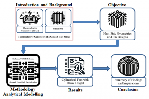
Here Figure 1 shows the temperature of the air within the heatsink fins increases during natural convection cooling as a function of heat energy from heat source. The hot-air pressure was less dense than that of the surrounding air. The thermal energy of the flow between physical systems is known as heat transfer. This is strongly influenced by the environment in which the system resides [2]. The device of the heat sink device deals with three operations heat energy transfer convection, conduction, and radiation.
Conduction $\quad \mathrm{Q}^{00}=-K \cdot \nabla t$
Convection $\quad \mathrm{Q}^{01}=-h \cdot\left(T_S-T_{\infty}\right)$
Radiation $\quad J=E+\rho G$
Figure 1. Workflow overview of heat sink geometry and fin design analysis for enhanced thermoelectric generator efficiency
High performance flexible thermoelectric generator made of polymetric thermoelectric composites and the heat sink fabrics, the generated power of 9.0 mw [1]. The micro sized heat sink based on silicon nanowires enhances heat dissipation by increasing surface to volume ration of the utilize of micro sized thermoelectric generator is significantly improved. It is very difficult to fabricate for real time applications [3]. Increased heat transfer results in increased output power optimum mass flow rate of maximum temperature difference and output power [2]. Heat sinks vertical cylinders with branched pin fins offer improved natural convection heat transfer performance compared to conventional finned cylinders. The study primarily focuses of heat transfer within the cylinder-fin system. It does not account for external factors that could affect heat transfer in real applications such as airflow variations and contaminants [4]. New heat sink design for natural convection explores its performance through numerical simulations and experiments and discusses the impact of thermal radiation, geometry optimization [5].
This work mainly focuses on a specific heatsink design that only has branched fins [6]. Copper heatsinks plan is more viable than aluminium heat sink inside of control yield. Both sorts of heat sinks require optimization in terms of control yield fetched and financial effectiveness [7]. The thermal efficiency of a heat sink in a double-height configuration were numerically studied. This study is not suitable for electronic circuits [8]. Optimal flow inlet velocity maximizes thermoelectric net power. Cross-cut plat-fin heat sinks have equal maximum power [9].
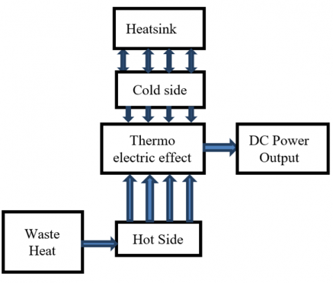
A thermoelectric generator (‘TEG’) is the devices such this transforms the heat energy into the electrical energy using of the principle of See beck effect. Figure 2 gives the details of methodology. It makes use of the change of temperature in between two sides of surfaces of the thermoelectric material to generate a voltage and subsequently produce electric power. The effects of Temperature gradient ∆T, and the geometrical parameters through which heat energy transported determine the rate at which conduction qk transfers heat [10].
Figure 2. Block diagram of thermoelectric generator with heat sink setup
3.1 Thermoelectric modules design
These modules consist of multiple pairs are ‘P-type’ of thermoelectric material, ‘N-type’ of Thermoelectric materials are electrically joined with in the series and the thermally connected with in allined. Thermoelectric materials are often made from semiconductors with different properties, allowing them to generate voltage when exposed to temperature gradients. Absorbing side: This one side of a thermoelectric Module is with direct connection accompanied by the heat source. It absorbs heat and allows it to transfer to the other side, creating a temperature difference across the thermoelectric material. On the heatsink side, this side surface of the thermoelectric modules make contact with the heatsink. It is designed to have a lower-Temperature than the heat absorbing side. Temperature differences are essential for electricity production. Module geometry of the heatsink.
The heatsink is the part responsible for dissipating heat from the thermoelectric modules. It typically consists of a thermally conductive material, such as aluminium or copper, with fins or other structures to increase surface area and improve heat dissipation through conduction, convection, and radiation. Electrical load: Electrical load is a device or system that consumes electrical energy generated by thermoelectric modules. It can be a battery charger, an electronic circuit or any other electrical device. Electricity output: It is connected to the electrical load, thus providing the necessary power for its operation. The basic operating principle is: When there is a temperature difference between thermoelectric modules, the temperature difference causes free electrons within Material for a be diffused from the hot side surface (P-type) to cold side (N-type). This movement of electrons creates a voltage difference known as the Seebeck voltage. By connecting multiple pairs of p-n modules in series, voltage will be accumulated and can be extracted into electrical energy. The heatsink plays an important role in maintaining low temperatures on cold side of surface of thermoelectric generator device module. It absorbs, dissipates the Heat to ambient environment, creating the necessary temperature gradient for continuous power generation. Overall, the thermoelectric generator system utilizes the Seebeck effect, temperature gradient, and heat sink is to transform the unwanted the heat energy into the functional electrical energy, providing efficient and sustainable way to harness heat as a power source.
$q K=-K A \frac{d T}{d x}$ (1)
Thermal resistance is a term used to describe heat sinks [2].
Wind tunnel tests measure thermal resistance and system impedance [3]:
$Q s a=\frac{T_s-T_a}{Q}=f(C F M)$ (2)
$\mathrm{T}_{\mathrm{s}}$ : Heat sink base temperature. ${ }^{\circ} \mathrm{C}$
$\mathrm{T}_{\mathrm{a}}$ : Approaching air temperature ${ }^{\circ} \mathrm{C}$
$\mathrm{Q}$ : Power provided to the heat sink
Airflow is volume flow rate; and flow velocity is the passage through the channel.
CFM: Cubic $\mathrm{ft} /$ minute
Volume flow rate $(\mathrm{V})$ units: $\left[\mathrm{m}^3 /\right.$ Second $]$
$\mathrm{V}=$ Velocity of air $\mathrm{V} \times$ Area of cross-section $\mathrm{A}_{\mathrm{c}}$
$Mass\, flow \,rate=\rho A c \vartheta=\rho \vartheta$ (3)
If must be higher than the flow rate of air, then the flow resistance faces. (Pressure loss) in the pressure drop across the flow length(pipe).
Pi: cross-section pressure.
$\Delta P=P i-P o$ (4)
$\Delta \mathrm{P}$ increases as $\mathrm{V}$ increases.
It depends on frictional resistance, shier stress, and sheer force.
$\Delta \mathrm{P}$ is the frictional pressure drop or/frictional loss.
System impedance increased the flowrate $=\mathrm{f}(\mathrm{v})$.
$\Delta \mathrm{P}$ depends on the functions $\mathrm{V}, \mathrm{S}, \mathrm{H}$, and the fluid properties.
$\mu=$ viscosity, $\rho=$ density.
$\frac{\Delta P}{L}=f v, s, H$ (5)
Pressure drop is also depending on length 'L’.
The fin spacing should be determined based on flow impedance [3], with few fins having a low object, a low-pressure drop, and many fins having a high object high-pressure drop. There is an optimal number of fins for a particular flow condition and fin spacing estimation.
$S_{\min }=1.3(H / V)^{0.5}$ (6)
H is the heatsink length in the flow direction.
'V' is the velocity (ft/min).
3.2 Fin efficiency
The efficiency of fin is one of the parameters that force the material to be used for high thermal conductivity. The heat sink fin can be flat and cylindrical, with one end of the heat flowing and dissipating to the surrounding air as it moves toward the other [4]. When fins must be isothermal, and they have infinite thermal conductivity.
Heat sink fin efficiency:
$\eta=\frac{\tanh (m L)}{m L}$ (7)
$m L=\sqrt{\frac{2 h f}{k t f} L f}$ (8)
3.3 Heat transfer theoretical model
The forced air over a tube appropriately firms up the heatsink in the ducted flow [4]. This makes sure the certain air passes across the channels created at the heatsink Fins [2]. When airflow was not ducted, some airflow passed through the heatsink [11] The flow bypass increased as the fin density and clearance increased but was unaffected by the inlet duct [3].
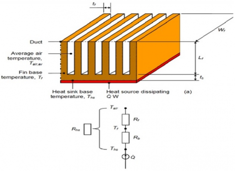
In Figure 3, the thermal resistance of a heatsink consists of two resistances. Those are 1). Resistance in base Rb, and 2). Resistance in the fins, Rf.
Base-resistance:
$R b=\frac{t b}{k A b}$ (9)
The thermal resistance of base fins to air:
$R f=\frac{1}{\eta n f w f(t f+2 \eta f L f)}$ (10)
$\eta f=\frac{\tanh m L c}{m L c}$ (11)
$m L c=\sqrt{\frac{2 h f}{k t f}} L f$ (12)
$D h=\frac{L c 4 A c h}{\rho c h}$ (13)
$\operatorname{Re}=\frac{4 G p}{\eta \pi D h u}$ (14)
$f=(0.79 \ln R e-1.64)^2$
$N u=\frac{\frac{f}{8}(R e-1000) P r}{1+12.7\left(\frac{f}{8}\right)^{20.5}\left(p r^{\frac{2}{3}}-1\right)}$ (15)
$h f=\frac{N u k_{a i r}}{D h}$ (16)
$\rho=\frac{\rho a t m}{\text { RaTin }}$ (17)
Figure 3. Heatsink (Source: Wikipedia)
A heatsink for a thermoelectric generator device (TEG) is a crucial component designed to enhance heat dissipation and maintain a temperature gradient high across the thermoelectric modules, thus maximizing efficiency of power generation. Heat sink in a TEG system serves the following purposes.
4.1 Heat absorption
The heat sink comes with direct contact in the hot side related thermoelectric device modules. Its primary function to absorbs and transfer heat from the heat source to the modules efficiently. This is typically achieved by ensuring good thermal contact and maximizing the surface area in contact with the modules.
4.2 Heat spreading
In addition to absorbing heat, the heat sink also helps in spreading the absorbed heat evenly across the thermoelectric modules. This uniform distribution of heat prevents localized hotspots, allowing for more effective utilization of the entire surface area of the modules.
4.3 Temperature transmission
The heat sink aids in keeping a lower temperature on cold side surface of device of thermoelectric generator module. By operation of dissipating Heat energy effectively, it helps establish and maintain the necessary temperature gradient required for efficient power generation. This temperature difference is critical for the Seebeck effect to occur and produce a voltage across the thermoelectric materials. Heat Dissipation: The heat sink is responsible for dissipating the absorbed heat from the thermoelectric modules into the surrounding environment. It typically utilizes various cooling mechanisms such as conduction, convection, and radiation to transfer heat away efficiently. To optimize heat dissipation, heat sinks for TEGs often incorporate the following features:
a. Finned structure: Fins are extended structures on the heat sink's surface that increase the available geometrical surface-area for the heat transfer. These fins intensity convective heat dissipation by promoting airflow and facilitating effective cooling.
b. Increased surface area: Heat sinks for TEGs are designed with a larger surface area to enhance heat dissipation. This can be achieved using extended fins, multiple fins, or a combination of design elements that maximize the exposed surface area.
c. Thermal conductivity: The heat sink material should have high thermal conductivity to proficiently transfer Heat energy from the thermoelectric modules to the Fins and the surrounding environment. Materials like aluminium and copper are commonly used for their excellent thermal conductivity properties.
d. Thermal interface material (TIM): A TIM is often used between the thermoelectric generator device modules and Heat sink to ensure optimal Thermal contacts, minimize any air gaps. This helps maximize heat transfer Efficiency amid modules and Heat sink.
e. Airflow enhancement: Airflow is vital for convective heat transfer. Some heat sink designs include features such as fans or ducts to improve airflow and increase the cooling effect. This can be especially important when the TEG system operates in environments with limited natural convection.
By effectively absorbing, spreading, and dissipating heat, a well-designed heat sink enhances the performance and efficiency of a thermoelectric generator device. It enables the structure to maintain required temperature gradient, thereby maximizing the electrical power output while keeping the thermoelectric modules within their optimal temperature range.
Heat sinks are typically based on their capacity to dissipate heat for a specific air curve. In this experiment was performed by laying a heat sink in a duct of rectangular shaped fin’s with insulated surface-area. Then the "Pressure, Temperature nearby the Inlet-outlet of the duct are monitored" [12], and power is required to maintain a certain temperature at the heatsinks values are generated and tabulated in Table 1 base surface under these conditions, the corresponding heat released by the heat sink device and Pressure loss across the duct can be estimated. The purpose of the application was to study typical experiments.
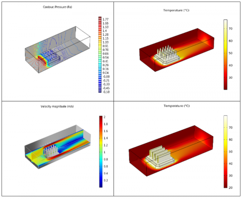
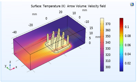
Conjugate the heat transfer interface for turbulent flow of the heat-transfer module Figure 4 shows automatically creates the model equations. You can provide the temperature of the air entering the module which serves as a boundary condition. The module calculates the heat-flux at the bottom of Heat sink boundary, assuming that the heat source temperature beneath the heat sink is keep at a constant temperature of 370°K for a certain heat transfer coefficient. Pure advective heat flow is used to control the heat flux at the output. The application sets all additional boundary criteria for the heat transfer problem to insulating borders. The flow problem specifies an adjustable inlet average velocity.
Table 1. Heat sink model geometry material parameters properties
|
Aluminum Properties |
||
|
Property |
Expression |
Unit |
|
Relative permeability |
1 |
1 |
|
Electrical conductivity |
2.326e7[S/m] |
S/m |
|
Coefficient of thermal expansion |
23.2e-6[1/K] |
1/K |
|
Heat capacity at constant pressure |
893[J/(kg*K)] |
J/(kg·K) |
|
Relative permittivity |
1 |
1 |
|
Density |
2730[kg/m3] |
kg/m³ |
|
Thermal conductivity |
155[W/(m*K)] |
W/(m·K) |
|
Young's modulus |
69[GPa] |
Pa |
|
Poisson's ratio |
0.33 |
1 |
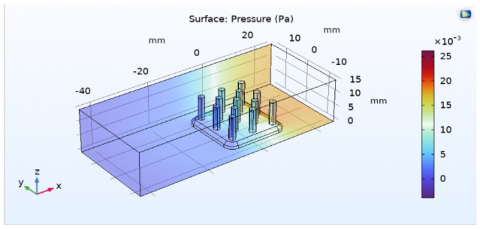
Figure 4. Cylindrical, hexagonal, rectangle fin heatsink model pressure (Pa)
Figure 5. Heat sink hexagonal shape model
Figure 6. Heat sink hexagonal shape model pressure (Pa)
Here, T0 stands for temperature about the heat source, which is adjusted to 370°K by the application, and q stands for the heat flow. N stands for the normal vector to the surface. After a simulation, the heat flow is integrated over the heat sink's bottom surface to determine the overall amount of power dissipated, which is displayed in the application's user interface (Figure 5).
A sample with two different numbers of heat fins is depicted in Figure 6. Keep in mind that as the number of fins rises, more power is lost. The pressure loss over the channel, however, also rises; it more than doubles while the power wasted rises by 20%. Finding the ideal number of fins for a particular pressure loss is the challenge.
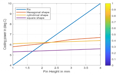
Many heatsink fin shape designs have been created, varying parameters such as fin height, fin thickness, fin spacing. Each design has been carefully simulated and tested. Increasing the blade height results in a 10 mm cylindrical blade shape at a temperature of 6.7℃ and a pressure loss of up to1.8 mm, a higher heat transfer coefficient and improved energy production efficiency. However, there is an optimal fin length beyond which further increases do not provide significant benefit.
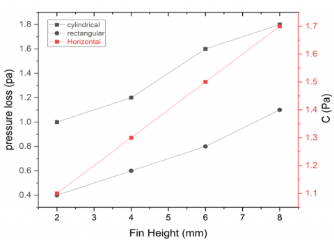
Figure 7. Heat sink fins height vs pressure loss
Here above Figure 7 is the analysis of pressure loss for different fin heights for different shapes of heat sink fins. After analyzing the results of the heat sink pressure loss is the heat exchange varies with different shapes of the heat sink fins and different heights of the heat sink fins. Hexagonal shape fin of the heat sink at fin height is 10mm more heat exchange through ambient air.
Table 2. Heat sink variable fin height with different shapes of heat sink air flowing pressure loss
|
S. No. |
Fin Height H (mm) |
Pressure Loss P (Pa) |
||
|
Cylindrical Shape |
Hexagonal Shape |
Rectangular Shape |
||
|
1 |
0 |
0 |
0 |
0.01 |
|
2 |
2 |
1.0 |
1.1 |
0.4 |
|
3 |
4 |
1.2 |
1.3 |
0.6 |
|
4 |
6 |
1.6 |
1.5 |
0.8 |
|
5 |
8 |
1.8 |
1.7 |
1.1 |
Figure 8. Heat sink fins heights vs temperature cooling power
Table 3. Heat sink variable fin height with different shapes of heat sink temperature heat exchange temperatures cooling power
|
S. No. |
Fin Height H (mm) |
Cooling Power in Temperature T (℃) |
||
|
Cylindrical Shape |
Hexagonal Shape |
Rectangular Shape |
||
|
1 |
0 |
0 |
0 |
0.01 |
|
2 |
2 |
5.8 |
6.1 |
5.3 |
|
3 |
4 |
6.1 |
6.2 |
5.4 |
|
4 |
6 |
6.5 |
6.3 |
5.5 |
|
5 |
8 |
6.7 |
6.4 |
5.6 |
Here Figure 7 shows the different fins with different shapes of the heat sinks, and in this graph plotted between the pressure loss and different fin heights tabulated in Table 2. The result is highest pressure loss at the cylindrical shape of the fin, height of the fin is 10 mm of the heat sink.
In this study Figure 8 shows the different fins with different shapes of the heat sinks, and in this graph plotted between the cooling power in degree centigrade and different fin heights. The result is highest cooling power is high at the cylindrical shape of the fin, height of the fin is 10 mm of the heat sink (Table 3).
5.1 Comparison of different heat sink models
Here the different heat sinks design modules, we selected the aluminium material, the aluminium material has low density, low weight, high thermal conductivity, and non-magnetic property of the material is not interference of magnetic with the hot surface of the application of thermoelectric generator, here comparing of the conventional and Analytical heat sinks, resulted values are tabulated in Table 4, we can choose the beat efficient heat sink for thermoelectric generator high performance. And comparing the different shapes of the fins and different heights of the fins, then the result is the best performance of the heat sink is cylindrical shape and height 10 mm of the Fin of the heat sink. Here consider the Table 4, from the design modules result analysis.
The result of the study is geometrical heatsink modules design and comparison of the fins geometry and fins.
After a few calculations and simulations of the modules, conclusions can be drawn. The fin heatsink design supports thermal cooling by heat absorption and pressure loss by heat convection, resulting in good long-term improvement in operational performance with intermittent use of the integrated chip. There are many options for choosing the appropriate fin size right size a given application. However, the solution depends on the temperature, density, and isothermal conductivity. By increasing thermal conductivity, the fins can obtain more energy. This would result in convection of the heat and pressure loss operations. From the results, the Fin peak and form of the heatsink fins will have a higher overall performance when cooling the temperature heatsink floor hooked up to the hot body of the integrated electronic circuit plate. The heatsink design module geometry and the material also plays a vital role in the heat flux. Thermal conductivity is the copper material is higher than a well-known material is aluminum, which was also designed in the simulations, and the heat convection time of the heatsink cooling depends on the fabrication.
Table 4. Comparison of different heat sinks fin shapes and cooling power, heat exchange air pressure loss
|
Fin Height H |
Temperature Cooling T in ℃ |
Average Pressure Loss P (Pa) |
||||
|
(mm) |
Cylindrical Shape |
Hexagonal Shape |
Rectangle Shape |
Cylindrical Shape |
Hexagonal Shape |
Rectangle Shape |
|
4 |
5.8 |
6.1 |
5.3 |
1.0 |
1.1 |
0.4 |
|
6 |
6.1 |
6.2 |
5.4 |
1.2 |
1.3 |
0.6 |
|
8 |
6.5 |
6.3 |
5.5 |
1.6 |
1.5 |
0.8 |
|
10 |
6.7 |
6.4 |
5.6 |
1.8 |
1.7 |
1.1 |
In this study we considered the heat sink fin shapes and heights of the heat sinks designed, compared, and analyzed. Through non-hallow fins. And another limitation is this study in only for thermoelectric generator wearable devices. It is not suitable for high temperatures, it suitable for low temperatures like human body temperatures only. And experimental commercially available heat sinks studies also consider getting high accuracy.
This study of the paper aims to get increased the performance of a Heat sinks in favor to a thermoelectric generator at low temperatures. The heat distribution through the heatsink, using simulation tool seeks to investigate and study the influence of the fin height and shape of cylindrical fins, 10 mm height of Fins change into the heat sink to improve the cooling performance and results. The carry-out efficiency of the Thermoelectric generator device improved at on temperatures. The geometrical fin cylindrical shape of a relative height fin and the fin must reach a high cooling level for the energy generation surface of potential through temperature gradient ∆T. As the temperature difference of the temperature gradient increases, then this efficiency of the thermoelectric generator increases. And future work for developments of the heat sink high performance for thermoelectric generator phase change material, environmental sustainability and flexibility of the fins design.
|
P |
Pressure Pa |
|
CP |
Specific heat, J. kg-1. K-1 |
|
g |
Gravitational acceleration, m.s-2 |
|
k |
Thermal conductivity, W.m-1. K-1 |
|
Nu |
Local Nusselt number along the heat source |
|
T |
Temperature ℃ |
|
V |
Volume flow rate m3/Second |
|
Qc |
Absorption heat W |
|
TEG |
Thermoelectric generator |
|
Greek symbols |
|
|
$\alpha$ |
Thermal diffusivity, m2. s-1 |
|
$\beta$ |
Thermal expansion coefficient, K-1 |
|
ρ |
Density Kg/m3 |
|
µ |
Dynamic viscosity, kg. m-1. s-1 |
[1] Lin, S., Zhang, L., Zeng, W., Shi, D., Liu, S., Ding, X., Yang, B., Liu, J., Lam, K.H., Huang, B., Tao, X. (2022). Flexible thermoelectric generator with high Seebeck coefficients made from polymer composites and heat-sink fabrics. Communications Materials, 3(1): 44. https://doi.org/10.1038/s43246-022-00263-1
[2] Wiriyasart, S., Naphon, P. (2021). Thermal to electrical closed-loop thermoelectric generator with compact heat sink modules. International Journal of Heat and Mass Transfer, 164: 120562. https://doi.org/10.1016/j.ijheatmasstransfer.2020.120562
[3] Van Toan, N., Ito, K., Tuoi, T.T.K., Toda, M., Chen, P.H., Sabri, M.F.M., Li., J., Ono, T. (2022). Micro-heat sink based on silicon nanowires formed by metal-assisted chemical etching for heat dissipation enhancement to improve performance of micro-thermoelectric generator. Energy Conversion and Management, 267: 115923. https://doi.org/10.1016/j.enconman.2022.115923
[4] Zhang, K., Li, M.J., Wang, F.L., He, Y.L. (2020). Experimental and numerical investigation of natural convection heat transfer of W-type fin arrays. International Journal of Heat and Mass Transfer, 152: 119315. https://doi.org/10.1016/j.ijheatmasstransfer.2020.119315
[5] Lee, G., Kim, C.S., Kim, S., Kim, Y.J., Choi, H., Cho, B.J. (2019). Flexible heatsink based on a phase-change material for a wearable thermoelectric generator. Energy, 179: 12-18. https://doi.org/10.1016/j.energy.2019.05.018
[6] Karthick, K., Suresh, S., Joy, G.C., Dhanuskodi, R. (2019). Experimental investigation of solar reversible power generation in Thermoelectric Generator (TEG) using thermal energy storage. Energy for Sustainable Development, 48: 107-114. https://doi.org/10.1016/j.esd.2018.11.002
[7] Elghool, A., Basrawi, F., Ibrahim, H., Ibrahim, T.K., Sulaiman, S.A., Ishak, M. (2018). Study on the performance of a thermo-electric generation model with two different materials of heat pipe-heat sink. In MATEC Web of Conferences. EDP Sciences, 225: 04009. https://doi.org/10.1051/matecconf/201822504009
[8] Rezania, A., Rosendahl, L.A. (2015). A comparison of micro-structured flat-plate and cross-cut heat sinks for thermoelectric generation application. Energy Conversion and Management, 101: 730-737. https://doi.org/10.1016/j.enconman.2015.05.064
[9] Jang, J.Y., Tseng, C.Y. (2015). Experimental and numerical analysis of built-in thermoelectric generator modules with an elliptical pin-fin heat sink. International Journal of Mechanical and Mechatronics Engineering, 9(5): 703-708. https://doi.org/10.5281/zenodo.1100490
[10] Elghool, A., Basrawi, F., Ibrahim, T.K., Habib, K., Ibrahim, H., Idris, D.M.N.D. (2017). A review on heat sink for thermo-electric power generation: Classifications and parameters affecting performance. Energy Conversion and Management, 134: 260-277. https://doi.org/10.1016/j.enconman.2016.12.046
[11] Simons, R.E., Ellsworth, M.J., Chu, R.C. (2005). An assessment of module cooling enhancement with thermoelectric coolers. Journal of Heat Transfer, 127(1): 76-84. https://doi.org/10.1115/1.1852496
[12] Atta, R.M. (2018). Thermoelectric cooling. In Bringing Thermoelectricity into Reality. London, UK: IntechOpen, pp. 247-267. http://doi.org/10.5772/intechopen.75791