Yong Chen![]() | Guoqi Zhang
| Guoqi Zhang![]() | Ao Song
| Ao Song![]() | Peibo You*
| Peibo You*![]()
© 2024 The authors. This article is published by IIETA and is licensed under the CC BY 4.0 license (http://creativecommons.org/licenses/by/4.0/).
OPEN ACCESS
The application of composite materials in bridge engineering is increasingly widespread, thanks to their excellent properties such as high strength, low density, and good corrosion resistance. However, in practical applications, composite material bridges often face complex thermal environments, especially thermal cycling, which imposes higher demands on the thermodynamic properties of the materials. Thermal cycling can cause not only heat transfer and expansion of composite materials but may also lead to material fatigue damage, thereby affecting the stability and safety of the bridge structure. Although existing research has some understanding of the thermal characteristics of composite materials, studies on fatigue damage mechanisms and thermal stress analysis under extreme temperature cycling conditions are still insufficient. This paper starts with the study of the thermodynamic properties of composite material bridges under thermal cycling. On the one hand, it analyzes the heat transfer and expansion deformation process of composite material bridges under thermal cycling. On the other hand, a fatigue damage constitutive model is established, and tests for model modification and constraint conditions are conducted. The research results show that the revised constitutive model can more accurately describe the fatigue damage behavior of composite materials under thermal cycling, which has important practical and theoretical value for guiding the design, construction, and maintenance of bridges.
composite material bridges, thermal cycling, thermodynamic properties, heat transfer analysis, fatigue damage, constitutive model, temperature effect
Bridges, as a key component of the transportation system, have their durability and stability directly related to the safety of people's lives and property and the sustainable development of society [1-4]. With composite materials gaining increasing application in bridge engineering due to their high strength, low density, and excellent corrosion resistance [5, 6], studying their thermodynamic performance in harsh environments has become an important topic in engineering science. Especially under thermal cycling, the thermal stress response and thermally induced deformation and fatigue behavior of composite material bridges have a profound impact on their lifecycle and safety performance [7-9].
The study of the thermodynamic properties of composite material bridges under the influence of thermal cycling is of significant importance for bridge design, construction, and subsequent maintenance [10, 11]. First, understanding the heat transfer mechanism and thermal expansion behavior of composite materials under temperature variations can guide material selection and bridge structural design [12-14]. Second, exploring the impact of thermal cycling on the fatigue performance of composite material bridges helps assess their reliability in long-term use, thereby guiding the development of maintenance strategies to extend the lifespan of the bridges [15-17].
Previous research has made some progress in evaluating the thermodynamic properties of composite materials, but there are still deficiencies. For example, most studies focus on the material properties at room temperature and pay insufficient attention to the fatigue behavior and thermal stress analysis of composite materials under extreme temperature cycling conditions [18-21]. Additionally, existing methods have not fully considered the non-linear behavior and temperature dependency of materials when simulating thermal expansion and fatigue damage, limiting the predictive accuracy and application scope of the models [22-25].
The main content of this study involves two major research areas: first, the analysis of the heat transfer process and the resulting expansion deformation of composite material bridges under multiple thermal cycles; second, the establishment of a constitutive model for thermal cycle fatigue damage of composite material bridges based on fatigue damage theory. Through the constructed model, this paper not only proposes a revision method to more accurately describe the fatigue characteristics of materials under temperature influence but also verifies the model's constraints and applicability with experimental data. These research findings will provide theoretical foundations and technical guidance for the design, construction, and maintenance stages of composite material bridges, having significant practical application value and theoretical research significance.
2.1 Analysis of heat transfer process
Bridge composite materials are designed to meet complex engineering needs and usually consist of two or more different materials, each complementing the other's characteristics. In bridge engineering, the design of composite materials aims to achieve a balance of excellent strength, durability, weight, and cost-effectiveness. Concrete is a commonly used base material in bridge construction, capable of withstanding high loads and relatively low in cost. In composite materials, concrete mainly provides strength and stiffness in the compression zone. Reinforcing bars or steel fibers in concrete mainly enhance its tensile strength, as concrete has relatively low tensile strength. Steel reinforcement significantly improves the overall structural strength of the composite material. Bridge composite materials may also include glass fiber-reinforced plastic, composed of glass fibers and resin, providing a lightweight strengthening option for composite material bridges. It not only offers good tensile strength but also excellent corrosion resistance. It can be used as external or internal reinforcement for concrete or to replace traditional steel bars, suitable for harsh environments, especially in high-corrosion settings. Bridge composites may also incorporate high-performance fiber-reinforced cementitious composites. These materials typically contain high-performance fibers, like polyethylene fibers, which can continue to bear loads after the concrete cracks, improving the material's toughness and durability. Such materials can be used in the tension zones of bridges to control cracking and improve seismic performance.
Figure 1. Characteristic point locations of the bridge composite material sample
To propose feasible and effective measures for mitigating damage to bridge composite materials under thermal cycling, it is necessary to consider the temperature stress caused by the differences in thermal expansion characteristics of the constituent materials and the internal and external temperature gradients. The difference in thermal expansion coefficients of different materials is a primary cause of internal stress. For example, the thermal expansion coefficients of concrete and steel are not the same; they expand or contract at different rates with temperature changes, leading to the accumulation of internal stress. Therefore, analyzing the differences in thermal expansion coefficients is necessary. Also, through thermal transfer analysis of composite materials, key factors leading to internal and external temperature gradients can be identified, such as the thermal conductivity of materials, environmental conditions, and their internal structural design. This is significant for guiding the design and maintenance of bridge composite materials in practical engineering.
In this paper, the heat transfer process under thermal cycling in bridge composite materials is first analyzed. Then, through detailed steps for establishing and solving the heat transfer problem, the temperature distribution and corresponding thermal stress of materials under various environmental conditions are predicted.
Figure 2. Characteristic surface locations of the bridge composite material sample
This paper first constructs a 3D model to describe how the heat within the composite material changes over time and across three-dimensional space. This model includes the material's density, specific heat capacity, and thermal conductivity, parameters that describe the material's ability to store and transfer heat. Figures 1 and 2 show the schematic diagrams of the characteristic points and surfaces of the bridge composite material samples. Assume the material density is represented by ϑ, specific heat capacity by z, temperature by s, and spatial position by a, b, and c. The following equation gives the three-dimensional transient heat conduction differential equation for the bridge composite material:
$\vartheta z\frac{\partial s}{\partial \pi }=\eta \left( \frac{{{\partial }^{2}}s}{\partial {{a}^{2}}}+\frac{{{\partial }^{2}}s}{\partial {{b}^{2}}}+\frac{{{\partial }^{2}}s}{\partial {{c}^{2}}} \right)$ (1)
To solve this model, appropriate boundary conditions must be set for the thermal exchange between the material surface and the surrounding environment. This includes considering the impact of ambient temperature on the material surface and the phenomenon of thermal convection at the surface.
By using dimensionless techniques, which involve converting temperature, time, and spatial coordinates into dimensionless forms, the mathematical expression and calculation process can be simplified. Dimensionless transformation also helps reveal the nature of similar processes under different conditions. For the composite material specimens of bridges, especially when their shape is a hexahedron, these dimensionless boundary conditions need to be applied to solve the heat exchange between the surface and the surrounding environment and the internal heat conduction problems.
Assume the excess temperature at position a at time π is represented by ϕ(a,π), and the initial excess temperature is denoted as ϕ0, where ϕ0=s0-sr. The initial temperature of the concrete and the ambient temperature are represented by s0 and sr, respectively. The root of the equation TAN(αvσ)=Yu/αvσ is denoted by α1, with the Biot number represented by Yu, where Yu=gσ/η. Half the thickness of a one-dimensional bridge concrete slab is represented by σ, and the thermal conductivity by x. The temperature solution for the one-dimensional transient heat conduction problem of a hexahedral-shaped composite material bridge specimen under the third type of boundary conditions can then be obtained by the following equation:
$\frac{\varphi \left( z,\pi \right)}{{{\varphi }_{0}}}=2{{r}^{-{{\left( {{\alpha }_{1}}\sigma \right)}^{2}}\left( \frac{\beta \pi }{{{\sigma }^{2}}} \right)}}\frac{SIN\left( {{\alpha }_{1}}\sigma \right)COS\left[ \left( {{\alpha }_{1}}\sigma \right)\left( \frac{a}{\sigma } \right) \right]}{{{\alpha }_{1}}\sigma +SIN\left( {{\alpha }_{1}}\sigma \right)COS\left( {{\alpha }_{1}}\sigma \right)}$ (2)
Due to the complexity of three-dimensional problems, numerical methods are usually employed for solutions. This means simplifying the three-dimensional problem into a series of one-dimensional problems, solving each separately, and then combining these one-dimensional solutions to obtain the temperature distribution throughout the entire three-dimensional space. Calculating the temperature change at any point within the material requires independently solving for the temperature distribution in each direction and synthesizing these results to obtain the overall temperature field. Assuming the temperature difference is represented by sr-s0, the density by ϑ, specific heat capacity by z, and surface heat transfer coefficient by g, the following equation provides the one-dimensional solution formula for the temperature at any point in a transient heat-conductive hexahedral bridge composite material:
$s\left( a,b,c,\pi \right)={{s}_{r}}+\left( {{s}_{0}}-{{s}_{r}} \right)\left[ \frac{\varphi \left( a,\pi \right)}{{{\varphi }_{0}}} \right]\left[ \frac{\varphi \left( b,\pi \right)}{{{\varphi }_{0}}} \right]\left[ \frac{\varphi \left( c,\pi \right)}{{{\varphi }_{0}}} \right]$ (3)
2.2 Analysis of the expansion deformation process
In bridge composite materials, different material phases possess distinct thermal expansion properties. When composite materials are subjected to temperature changes, these material phases expand or contract at varying rates and magnitudes. For example, in bridge composite materials, the mortar and aggregate have different coefficients of thermal expansion. During temperature changes, materials with a larger coefficient of thermal expansion will expand more than those with a smaller coefficient, leading to significant mechanical stress at the interface. Moreover, the interface between different material phases in the composite material is key to determining the material's overall performance. The interface between aggregate and mortar experiences particularly high stress, as it is the point where two different material phases bond together. Any non-coordinated deformation directly translates into interfacial stress, thereby increasing the risk of damage at this point. If these changes are not coordinated, i.e., there is a significant difference in thermal expansion coefficients, stress concentration will occur at the material interface, leading to damage, especially in areas where aggregate and mortar are bonded. To address the stress issues caused by thermal expansion differences between aggregate and mortar in bridge composite materials, measures such as selecting aggregate and mortar materials with closer thermal expansion coefficients, improving the bonding interface between aggregate and mortar through surface treatment or coating techniques, or designing the internal structure of the material to accommodate or buffer thermal expansion can be adopted to reduce the damage caused by this thermal expansion incoordination.
In the actual composition of bridge composite materials, coarse aggregates, fine aggregates, cement mortar, and possibly other additives or cellulosic materials are usually included. Coarse aggregates are typically composed of crushed stone or gravel, while fine aggregates may be sand. Cement mortar, a mixture of cement, water, and fine aggregate, acts as the binder in the composite material. These components, due to their differing physical properties, particularly in terms of thermal expansion coefficients, result in complex interactions during thermal cycling.
In thermal cycling, temperature changes first affect the material's surface and then gradually penetrate inward. Since coarse aggregates usually have lower coefficients of thermal expansion, their temperature response is relatively slow, meaning their expansion or contraction lags behind that of the cement mortar. When the external environmental temperature rises, the cement mortar expands before the aggregates. This asynchronous expansion behavior causes a displacement difference at the interface between the aggregates and the cement mortar, resulting in stress. Similarly, when the temperature drops, the cement mortar contracts before the aggregates, further increasing stress. To coordinate this displacement deformation, the ratio of the cement mortar can be adjusted to increase its flexibility, allowing it to better absorb stress caused by the expansion of the aggregates, thereby reducing the formation of cracks. Assume the radius of the aggregate is represented by E, the thermal expansion coefficients of the aggregate and cement mortar are represented by βx and βl, respectively, the elastic moduli by Rx and Rl, Poisson's ratios by ωx and ωl, temperature change by ∆S, the radial displacements caused by temperature changes in the cement mortar and aggregate are represented by σlS and σxS, and the radial displacements caused by interfacial thermal stress in the cement mortar and aggregate are represented by σlδ and σxδ. The coordination of radial displacement deformation at the interface can be characterized by the following equation:
${{\sigma }_{lS}}+{{\sigma }_{l\delta }}={{\sigma }_{xS}}+{{\sigma }_{x\delta }}$ (4)
Due to the different coefficients of thermal expansion between aggregate and cement mortar, expansion or contraction mismatches between them under rising or falling environmental temperatures can generate tensile or compressive stress at the contact surface. If this stress exceeds the material's tensile or compressive limits, it could lead to cracking at the interface. This paper further calculates the normal stress A at the interface between coarse aggregate and cement mortar, taking into account the shape, size, and distribution of the aggregate, as well as the thickness and elastic modulus of the cement mortar. By integrating these factors, the stress distribution at the interface can be derived to predict and assess potential crack risks. The calculation formula is:
$A=\frac{\left( {{\beta }_{l}}-{{\beta }_{x}} \right){{R}_{l}}{{R}_{x}}}{{{R}_{l}}\left( 1-{{\omega }_{x}} \right)+{{R}_{x}}\left( 1+{{\omega }_{l}} \right)}\Delta S$ (5)
The following formula calculates the stress at a distance e from the center of the aggregate in the cement mortar:
${{\delta }_{e}}=\frac{A{{E}^{2}}}{{{e}^{2}}}=\frac{\left( {{\beta }_{l}}-{{\beta }_{x}} \right){{R}_{l}}{{R}_{x}}}{{{R}_{l}}\left( 1-{{\omega }_{x}} \right)+{{R}_{x}}\left( 1+{{\omega }_{l}} \right)}\Delta S\frac{{{E}^{2}}}{{{e}^{2}}}$ (6)
${{\delta }_{\varphi }}=-\frac{A{{E}^{2}}}{{{e}^{2}}}=-\frac{\left( {{\beta }_{l}}-{{\beta }_{x}} \right){{R}_{l}}{{R}_{x}}}{{{R}_{l}}\left( 1-{{\omega }_{x}} \right)+{{R}_{x}}\left( 1+{{\omega }_{l}} \right)}\Delta S\frac{{{E}^{2}}}{{{e}^{2}}}$ (7)
During thermal cycling, cement mortar experiences significant volume changes due to its higher coefficient of thermal expansion. These changes lead to the development of radial compressive stress and circumferential tensile stress within the cement mortar. Radial compressive stress is due to the outward expansion of the cement mortar pressing against the surrounding aggregate; circumferential tensile stress arises as the expanding mortar tries to maintain volumetric consistency along the circumference. To analyze these stresses in detail, finite element analysis or other numerical simulations are needed in practical applications to simulate the specific impact of temperature changes on the volume changes of cement mortar. The analysis should consider the thermal properties of the cement mortar, the geometric structure of the composite material, and external temperature conditions. Further, the stress analysis of cement mortar should consider how microcracks caused by the mismatch between aggregate and mortar affect the macroscopic stress distribution, and how these microcracks affect the overall performance and durability of the composite material after multiple thermal cycles.
During thermal cycling, the Poisson's ratio significantly impacts the thermal stress distribution in materials. For bridge composite materials, analyzing the Poisson's ratio requires considering the individual Poisson's ratios of concrete mortar and aggregate, as well as their combined impact on the composite system. Particularly, when considering the mismatch in thermal expansion between mortar and aggregate, the differing Poisson's ratios can lead to complex stress states, especially near the interface between aggregate and mortar. Combining the analysis of stress and Poisson's ratio, to mitigate the deterioration of bridge composite materials under thermal cycling, strategies could include reducing the thermal conductivity of concrete, minimizing the difference in the coefficients of thermal expansion between the constituent phases, adjusting the elastic modulus, and optimizing the surface heat transfer coefficient. These approaches aim to lower the coefficient of thermal expansion of bridge composite materials, prolong their service life, and maintain their structural integrity and safety.
In bridge engineering, the fatigue damage constitutive model of composite materials is a mathematical model used to describe the stress-strain behavior of materials under repeated or cyclic loading. Such models are crucial for predicting and assessing the performance of bridges during long-term service, especially when considering the effects of thermal cycling. The constitutive model constructed in this paper provides a framework to predict the mechanical response of composite materials under various thermal cycling conditions. This includes analyzing material strain accumulation, microcrack formation, and expansion, and other fatigue behaviors under repeated thermal stress. Figure 3 presents a flowchart for the fatigue state analysis of bridge composite materials.
Figure 3. Flowchart of fatigue state analysis for bridge composite materials
3.1 Model construction
This paper divides the damage evolution process of composite material bridges under thermal cycling into two phases: performance enhancement and performance degradation. During the performance enhancement phase, bridge composite materials might experience a "strengthening" phenomenon under initial cyclic loading, where the dynamic elastic modulus increases due to the closure of microcracks or adjustment of the internal structure of the material. In the performance degradation phase, as the number of cyclic loadings increases, microcracks within the material begin to expand, leading to a gradual reduction in material performance. This phase is typically characterized by the accumulation of damage factors and exhibits nonlinear characteristics. This nonlinearity in fatigue damage is often related to the accumulation process of internal damage. In the case of composite material bridges, this means that the growth of damage is not at a constant rate but varies with the number of loading cycles, involving the initiation, expansion, and eventual possible formation of macroscopic cracks in the material. Considering the impact of the performance enhancement phase, the D-n curve can be shifted to ensure the accuracy of the damage model during the performance degradation phase. The magnitude of the shift may depend on the impact coefficient of the performance enhancement phase, which can be determined through experiments or theoretical analysis. Combining the above principles, a complete damage evolution model including both performance enhancement and degradation phases can be established. This model can reflect not only the possible strengthening effects in the initial phase but also describe the gradual reduction in material performance as the number of loading cycles increases.
Bridge composite materials often endure multiaxial stress in practical applications, meaning the material is subjected to forces in multiple directions simultaneously. For example, bridge decks under vehicle loads may experience compressive stress, tensile stress, and shear stress at the same time, often involving nonlinear damage behavior under multiaxial stress states. Multiaxial nonlinear cumulative fatigue damage accumulation models are advanced analytical tools used to describe and predict material fatigue behavior under complex stress states. In multiaxial nonlinear cumulative fatigue damage research, selecting appropriate damage variables is crucial for describing the material damage state, predicting life, and assessing performance. Direct measurement of internal stress or strain in materials is both complex and costly, especially for heterogeneous materials like composites. In contrast, dynamic elastic modulus can be relatively easily measured through non-destructive testing. Assuming the elastic modulus of the specimen after v thermal cycles is represented by R(v), and the initial elastic modulus is represented by R(0), the expression is:
$F=1-\frac{R\left( v \right)}{R\left( 0 \right)}$ (8)
To construct an accurate thermal cycling fatigue damage constitutive model, it is necessary to first determine the actual load conditions produced by thermal cycling in bridge composite materials. This includes identifying internal stress states caused by temperature changes, such as tensile and compressive stresses due to differences in coefficients of thermal expansion, and how these stresses vary over time and with temperature cycles. Furthermore, analyzing whether the loading caused by temperature changes is non-proportional, that is, whether the stress or strain in different directions changes disproportionately. In composite materials, due to anisotropy and differences in thermal expansion coefficients of different material components, such non-proportional loading is likely to occur. By replacing the main control parameter ∆γzeew/2 with ∆γ/2, the thermal cycling fatigue damage rate equation shown below can be constructed:
$dF={{\left( 1-F \right)}^{{{\theta }_{1}}}}{{\theta }_{2}}fv$ (9)
The damage parameters θ1 and θ2 in the equation can be obtained as follows:
${{\theta }_{1}}=\beta \left( {\Delta \gamma _{rw}^{ze}}/{2}\;,{{\delta }_{l}} \right)=1-\frac{G\left( J{{\left( {\Delta \gamma _{rw}^{ze}}/{2}\; \right)}^{v}}-{{\delta }_{-1}}\left( 1-y{{{\bar{\delta }}}_{G}} \right) \right)}{xLN\left| J{{\left( {\Delta \gamma _{rw}^{ze}}/{2}\; \right)}^{v}}-{{\delta }_{-1}}\left( 1-y{{{\bar{\delta }}}_{G}} \right) \right|}$ (10)
The selection of damage parameters directly affects the accuracy and reliability of the model. The choice of damage parameters is mainly influenced by the material's physical properties (elastic modulus, Poisson's ratio, etc.), loading conditions (stress level, stress ratio, loading frequency), environmental factors (temperature range, rate of temperature change, number of temperature cycles), and structural characteristics (component size, geometric shape).
${{\theta }_{2}}={{\left[ \frac{J{{\left( {\Delta \gamma _{rw}^{ze}}/{2}\; \right)}^{v}}}{{{M}_{0} }\left( 1-{y}'{{{\bar{\delta }}}_{G}} \right)} \right]}^{\alpha }}$ (11)
Considering the impact of thermal loads on the material damage process, it is necessary to evaluate the rate of damage, i.e., how damage accumulates over time. The assessment of damage rate needs to consider the material's fatigue characteristics, including its durability and fatigue limit. Constructing a damage accumulation model to simulate how internal damage in the material develops with the increase in the number of cycles under continuous thermal cycling. This model needs to include the initial state of damage, the rate of damage evolution, and potential cumulative effects of damage. Integrating Eq. (9) yields the thermal cycling fatigue damage constitutive model for bridge composite materials, as follows:
$F=1-{{\left[ 1-{{\theta }_{2}}v\left( 1-{{\theta }_{1}} \right) \right]}^{\frac{1}{1-{{\theta }_{1}}}}}\begin{matrix} {} & {{\theta }_{1}}\ne 1 \\\end{matrix}$ (12)
When the damage degree F is 1, the number of cycles v for thermal cycling fatigue failure of bridge composite materials can be considered as the fatigue life Vd. By substituting v=Vd into the above equation, the following equation is obtained:
$F=1-{{\left( 1-\frac{v}{{{V}_{d}}} \right)}^{\frac{1}{1-{{\theta }_{1}}}}}\begin{matrix} {} & {{\theta }_{1}}\ne 1 \\\end{matrix}$ (13)
3.2 Model modification
The behavior of bridge composite materials in thermal environments exhibits complex nonlinear characteristics, particularly in the initial stages of thermal exposure, where short-term phenomena that differ from long-term behavior may occur. These phenomena need to be appropriately considered and modified in the fatigue damage constitutive model. Assuming the modification coefficient is represented by j, the expression for the modified model would be:
$F=1-j{{\left[ 1-{{\theta }_{2}}v\left( 1-{{\theta }_{1}} \right) \right]}^{\frac{1}{1-{{\theta }_{1}}}}}\begin{matrix} {} & {{\theta }_{1}}\ne 1 \\\end{matrix}$ (14)
$F=1-j{{\left( 1-\frac{v}{{{V}_{d}}} \right)}^{\frac{1}{1-{{\theta }_{1}}}}}\begin{matrix} {} & {{\theta }_{1}}\ne 1 \\\end{matrix}$ (15)
3.3 Model constraint conditions verification
To reduce the disparity of the thermal cycling fatigue damage constitutive model for bridge composite materials, it is necessary to verify the model equation with multiple constraint conditions.
(1) Boundary conditions. The model needs to define the initial damage state of the material before the start of thermal cycling, including any pre-existing cracks, voids, or other defects. The state of the initial microstructure, including fiber distribution, porosity, etc., is also an important initial boundary condition. Let the initial undamaged F of bridge composite materials be 0, and F be 1 at the time of fatigue failure, then:
$v=0,F=0,v={{V}_{d}},F=1$ (16)
(2) Thermodynamic constraint conditions. In the thermal cycling fatigue damage constitutive model for bridge composite materials, thermodynamic constraint conditions provide fundamental principles about energy dissipation and damage progress. Since low-cycle fatigue damage during thermal cycling is considered irreversible, the second law of thermodynamics, especially the part related to entropy increase, is crucial to ensure the physical rationality of the constitutive model. The irreversible nature of fatigue damage means that once damage occurs, it cannot be fully restored by simple physical processes. In the constitutive model, this irreversibility is typically represented by the monotonic increase of the damage variable. In this paper, the constitutive model F(v) is approximated as a monotonically increasing function, then:
${\partial F}/{\partial v}\;>0$ (17)
(3) Physical constraint conditions. In the thermal cycling fatigue damage constitutive model for bridge composite materials, physical constraint conditions are used to ensure that the model's predictions remain consistent with actual physical phenomena. Physical constraint conditions require that the model reflects that under the same thermal cycling conditions, greater internal expansion forces will lead to more significant material damage. This is because larger thermal expansion forces increase the micro stresses within the composite material, thereby increasing the likelihood of crack formation and expansion, namely:
${{{\partial }^{2}}F}/{\partial v\partial \delta }\;>0$ (18)
The constructed constitutive model is verified based on the above three constraint conditions.
For boundary conditions, Eq. (16) satisfies V=0, F=0, V=VD, F=1;
For thermodynamic constraint conditions, taking the partial derivative of Eq. (17), the following condition satisfies the verification criteria:
$\frac{\partial F}{\partial V}=\frac{1}{{{V}_{D}}\left( 1-{{\theta }_{1}} \right)}j{{\left( 1-\frac{v}{{{V}_{D}}} \right)}^{{}^{{{\theta }_{1}}}/{}_{\left( 1-{{\theta }_{1}} \right)}}}>0$ (19)
For physical constraint conditions, taking the partial derivative of Eq. (18), the following condition satisfies the verification criteria:
$\frac{\partial F}{\partial V\partial \delta }=\frac{{{\theta }_{1}}{{^{\prime }}^{2}}{{\theta }_{2}}{{^{\prime }}^{2}}v}{{{\left( 1-{{\theta }_{1}} \right)}^{2}}}k{{\left( 1-\frac{v}{{{V}_{D}}} \right)}^{{}^{\left( 2{{\theta }_{1}}-1 \right)}/{}_{\left( 1-{{\theta }_{1}} \right)}}}>0$ (20)
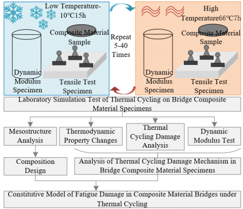
Figure 4. Experimental scheme
By integrating these physical constraint conditions into the thermal cycling fatigue damage constitutive model of bridge composite materials, it can be ensured that the model is not only mathematically complete but also physically credible. These constraint conditions help in precisely predicting the thermal cycling damage behavior of composite materials in actual bridge applications, thereby providing important guidance for bridge design, evaluation, and maintenance. Figure 4 presents the experimental scheme.
Figure 5 shows the temperature gradient variation curve at different locations in a single thermal cycle of bridge composite material. It can be seen from the figure that for the position (250,250,250), a peak value of 1.3 is reached between the time points 40 to 60, then it gradually decreases, reaching a second peak of 2.3 at 160, and then decreases again. This indicates that the material at this location might be affected by temperature fluctuations, possibly due to internal heat sources or external environmental temperature changes. For the position (250,250,125), the temperature remains stable from 20 to 60 time points, then gradually decreases, but reaches a peak of 180 at time point 160, followed by a significant decrease in temperature. This might suggest that the material at this location has a buffering effect in the thermal cycle, but when a certain critical point is reached, the temperature gradient change significantly increases. For the position (250,250,0), the temperature rises rapidly at the beginning, reaching 330 at time point 40, then decreases at time point 60, but reaches the highest peak of 700 at time point 160, followed by a rapid decline. This indicates that this location might be directly exposed to a heat source or the most direct thermal influence.
It can be concluded that different material combination positions show different temperature gradient changes during the thermal cycle, which may imply that the thermal expansion and heat conduction characteristics within the composite material vary with the proportion and location of the materials. For instance, positions closer to the heat source exhibit greater temperature fluctuations in the thermal cycle. At certain time points, such as time point 160, all positions experience peak temperature gradients, which might indicate that the thermal stability of the composite material is challenged under extreme thermal cycling conditions. Due to the repeated fluctuations in temperature gradients, especially when reaching very high or low temperature gradients, the material might undergo thermal fatigue damage. This kind of damage could affect its mechanical properties and durability, so considering fatigue due to thermal cycling is very important in the design of composite material bridges.
Figure 5. Temperature gradient variation curve at different locations in single thermal cycle of bridge composite material
Figure 6 presents the temperature change curves inside the composite material of a bridge at depths of 20mm and 40mm, after undergoing different numbers of thermal cycles. The data includes temperature changes over time at these two depths after 0, 60, and 120 thermal cycles. It can be observed that after 0, 60, and 120 thermal cycles, the temperature at both depths starts to decrease from the same initial temperatures of 65°C or 63°C. This indicates that the material might have been heated to a uniform initial temperature at the start of the experiment. The graph shows that with an increasing number of thermal cycles, the rate of temperature decrease inside the material slows down. This might suggest a reduction in thermal conductivity after multiple thermal cycles, possibly due to changes in the internal structure of the material, such as the formation of microcracks or the accumulation of internal stress. As the number of thermal cycles increases, the time it takes for the initial temperature to drop to a stable temperature becomes longer, indicating that the thermal stability of the material might decrease after repeated thermal cycling. Thermal fatigue damage in composite materials could lead to a degradation of thermophysical properties. The thermal response characteristics of the material show changes with an increasing number of thermal cycles, which could be a direct result of thermal fatigue damage. At the deeper position (40mm), the rate of temperature decrease is relatively slower, possibly because the heat takes longer to transfer through the material. The temperature change trends at both depths are broadly similar, but at the deeper position, the material's response to thermal cycling seems slower. In conclusion, the thermodynamic properties of composite material bridges might degrade under repeated thermal cycling, manifesting as a reduction in thermal conductivity and thermal stability. This degradation could affect the long-term stability and durability of the structure, especially in environments with frequent temperature fluctuations. Considering these factors is crucial in the design and evaluation of composite material bridges.
(a) Depth 20mm
(b) Depth 40mm
Figure 6. Temperature changes during heating process inside bridge composite materials under thermal cycling
(a) Depth 20mm
(b) Depth 40mm
Figure 7. Cooling process temperature change curve of bridge composite material under thermal cycling
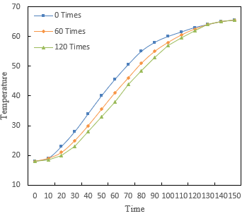
Figure 7 shows the warming process of bridge composite materials at depths of 20mm and 40mm after undergoing different numbers of thermal cycles. These data can be used to analyze how the internal thermal behavior of the material changes with an increasing number of thermal cycles. Each graph displays the process of heating from 18℃ to a certain temperature, over intervals of 10 minutes, recording temperature changes over 150 minutes. The graphs indicate that at both 20mm and 40mm depths, the rate of temperature increase in the material gradually decreases as the number of thermal cycles increases. This may be due to microstructural changes in the material caused by fatigue, leading to an increase in thermal capacity or a reduction in thermal conductivity. After repeated thermal cycling, the final temperature reached by the material within 150 minutes is slightly reduced. This suggests that the thermal stability of the material may be affected by thermal fatigue damage. Thermal fatigue damage in composite materials could cause changes in their heat transfer characteristics. The variation in the heating curves after multiple thermal cycles may reflect the cumulative effect of this damage. At the deeper location (40mm), the rate of heating is relatively slower, indicating that the transfer of heat to deeper levels is slower, which is related to the material's thermal diffusion characteristics. In summary, after multiple thermal cycles, the thermal response of bridge composite materials slows down, indicating that thermal stability and heat transfer characteristics may have been affected by fatigue damage. These changes could affect the long-term performance and reliability of the structure, especially in applications with frequent thermal loads. Therefore, when designing and evaluating composite material structures, it is necessary to consider the potential impact of thermal cycling on material properties.
Table 1. Compressive strength test results of bridge composite material under thermal cycling
|
Thermal Cycle Count |
0 |
30 |
60 |
90 |
120 |
|
Compressive Strength |
61.2 |
57.9 |
54.8 |
51.6 |
47.8 |
|
Relative Compressive Strength |
100.0 |
94.5 |
92.1 |
84.6 |
78.9 |
|
Strength Loss Rate |
0.0 |
4.3 |
8.9 |
13.8 |
21.4 |
Figure 8. Compressive strength change graph of bridge composite material under thermal cycling
Table 1 and Figure 8 show the compressive strength test results of bridge composite materials after undergoing different numbers of thermal cycles. The decrease in compressive strength and changes in relative compressive strength reflect the thermodynamic stability and structural integrity of the material under thermal cycling conditions. It can be observed that with an increasing number of thermal cycles, the compressive strength of the composite material decreases from 61.2 to 47.8. This indicates a gradual degradation of the material under the influence of thermal cycling. The relative compressive strength decreases from 100% to 78.9%, further verifying the degradation of material performance. With an increasing number of thermal cycles, the strength loss rate rises from 0% to 21.4%. This value can be seen as a quantitative indicator of the impact of thermal cycling on material performance. The conclusion can be drawn that the compressive strength of the composite material significantly decreases with an increasing number of thermal cycles, suggesting that the material might undergo some irreversible chemical or physical changes during thermal cycling, such as the growth of microcracks, degradation of material interfaces, or rearrangement of molecular structures. Continuous thermal cycling leads to a gradual decrease in the strength of composite materials, which could affect the long-term durability and safety of bridges. In the design and evaluation of composite material bridges, this strength reduction caused by thermal cycling must be considered. Design may require the introduction of certain safety factors or the selection of materials more resistant to thermal cycling. The fatigue life of the material may need to be predicted based on the strength loss rate at specific thermal cycle counts. Careful assessment is needed to determine after how many thermal cycles the material will reach the critical point of its service life. Continuous use under high temperatures or periodic exposure in high-temperature environments may require materials with better thermal stability. These test results are crucial for predicting the thermal stability of the material and determining its applicability under extreme temperature conditions.
Table 2. Static elastic modulus test results of bridge composite material under thermal cycling
|
Thermal Cycle Count |
0 |
60 |
120 |
|
Static Elastic Modulus |
35.9 |
35.2 |
31.2 |
|
Relative Static Elastic Modulus |
100.0 |
92.8 |
82.4 |
|
Static Elastic Modulus Loss Rate |
0.0 |
6.7 |
15.9 |
Data provided in Table 2 and Figure 9 show the static elastic modulus test results of bridge composite materials under different numbers of thermal cycles, which can be used to analyze the impact of thermal cycling on the material's stiffness. Initially, at 0 thermal cycles, the static elastic modulus is 35.9, representing the baseline modulus of elasticity for the composite material without any thermal cycling. The static elastic modulus slightly decreases to 35.2, with the relative static elastic modulus dropping to 92.8%, and the loss rate of static elastic modulus being 6.7%. This indicates that even after 60 thermal cycles, the material's structure remains relatively intact, but some degree of performance degradation can be observed. The static elastic modulus further decreases to 31.2, with the relative static elastic modulus dropping to 82.4%, and the loss rate increasing to 15.9%. This larger loss rate suggests that after more thermal cycles, the material's damage is more severe, and its stiffness significantly reduced. The data indicate that the static elastic modulus of the composite material decreases with an increasing number of thermal cycles. This degradation might be due to changes in the material's microstructure caused by high-temperature cycling, such as thermal cracking, oxidation, or other chemical changes. The static elastic modulus is an indicator of a material's ability to resist deformation. With the reduction in static elastic modulus, the material is more likely to deform under load, which may affect the overall stability and lifespan of the bridge structure. Significant loss in modulus of elasticity indicates substantial changes in the material's mechanical properties after thermal cycling, pointing to a decrease in thermal stability after experiencing high-temperature cycles. In bridge design, the potential impact of thermal cycling on material properties must be considered. Design may require additional measures, such as using more heat-resistant materials, increasing cross-sectional dimensions, or introducing other reinforcement measures, to compensate for the impact of the decrease in modulus of elasticity on structural performance. The impact of thermal cycling on the static elastic modulus of composite materials suggests that the fatigue life may be shortened due to degradation in material properties. Therefore, when assessing the material's fatigue life, the impact of thermal cycling must be considered.
Figure 10 presents the mortar damage and static elastic modulus of bridge composite materials after undergoing different numbers of thermal cycles. The data in the figure can be used to assess the impact of thermal cycling on the performance of bridge composite materials. It shows that the average damage value of the mortar linearly increases from 0.0000 at 0 thermal cycles to 0.2640 at 120 cycles. The increase in damage is continuous and gradual, suggesting that damage accumulates with the number of thermal cycles. The damage growth rate appears to remain relatively constant with increasing thermal cycle counts, but there is a slight acceleration in the last few data points. The loss rate of elastic modulus starts from 0.00% and grows with the number of thermal cycles, reaching 19.50% at 120 cycles. The growth of the loss rate is not entirely linear, and the rate of increase accelerates with the number of thermal cycles, especially in the later stages (around 100 thermal cycles and beyond).
Figure 9. Static elastic modulus change graph of bridge composite material under thermal cycling
Figure 10. Mortar damage and static elastic modulus of bridge composite material after different numbers of thermal cycles
It can be concluded that bridge composite materials experience continuous damage and performance degradation after undergoing thermal cycling. This could be due to microcracking caused by thermal stress, thermal aging, or changes in the chemical structure. The data indicate that the damage to the mortar and the loss of elastic modulus are cumulative, meaning that the damage caused by thermal cycling is irreversible and difficult to restore with simple repair measures. As the number of thermal cycles increases, the loss of elastic modulus in the composite material intensifies, indicating a reduction in thermal stability. Under extreme temperature cycling conditions, the material may not be able to maintain its original mechanical properties. The long-term behavior of composite materials under the influence of thermal cycling must be considered in bridge design. It may be necessary to select materials with higher thermal stability or design more conservative structures to compensate for the loss of strength and stiffness caused by thermal cycling. For existing bridges, regular assessment of the impact of thermal cycling on the material's elastic modulus is essential to ensure structural safety. As the loss rate increases, the structure may require more frequent inspections and possible reinforcement.
Table 3. Dynamic elastic modulus test results of bridge composite material under thermal cycling
|
Thermal Cycle Count |
0 |
60 |
120 |
|
Fundamental Vibration Frequency |
2354 |
2189 |
2056 |
|
Relative Static Elastic Modulus |
100.0 |
87.9 |
72.5 |
Figure 11. Change graph of dynamic elastic modulus of bridge composite material under thermal cycling
Table 3 and Figure 11 show the fundamental vibration frequency and changes in the dynamic elastic modulus of bridge composite materials under different numbers of thermal cycles. These data can be used to evaluate the impact of thermal cycling on the dynamic response characteristics of the materials. Initially, at 0 thermal cycles, the fundamental vibration frequency is 2354, and the relative dynamic elastic modulus is 100.0%, representing the initial vibration characteristics of the composite material without any thermal cycling. After 60 thermal cycles, the fundamental vibration frequency decreases to 2189, and the relative dynamic elastic modulus drops to 87.9%, indicating a reduction in the material's dynamic stiffness. After 120 thermal cycles, the fundamental vibration frequency further decreases to 2056, and the relative dynamic elastic modulus significantly drops to 72.5%, showing further degradation of material performance.
It can be concluded that the dynamic performance of bridge composite materials significantly decreases with an increasing number of thermal cycles, suggesting that the material may undergo microstructural changes, such as thermal cracking, material interface deterioration, or polymer chain breaking. The significant reduction in dynamic elastic modulus indicates that the material's ability to withstand dynamic loads decreases after thermal cycling. Dynamic load-bearing performance, more than static load-bearing, reflects the material's actual working condition and reliability. The reduction in fundamental vibration frequency may change the bridge's response behavior during normal operation, which could affect the bridge's service life and safety. The impact of thermal cycling on the dynamic performance of composite materials needs to be considered in bridge design and safety assessment. Design may require the selection of materials with higher heat resistance or the application of additional protective measures.
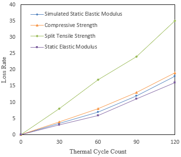
Figure 12. Comparison of mechanical property degradation test results and simulated damage in bridge composite materials
Figure 12 lists the changes in the simulated static elastic modulus, compressive strength, split tensile strength, and measured static elastic modulus of bridge composite materials after different numbers of thermal cycles. Assuming all values are relative or percentage changes, the trend of mechanical property degradation and the relationship between experimental and simulated data can be analyzed. The simulated and measured static elastic modulus both increase linearly with the number of thermal cycles. This shows that the trends of simulation and measurement are consistent, and the stiffness of composite materials decreases with an increasing number of thermal cycles, with the simulated values slightly higher than the measured values, possibly indicating a conservative approach in assessing material damage. The compressive strength and split tensile strength also increase with the number of thermal cycles, indicating a gradual decline in the compression and tensile load-bearing capacity of composite materials. Especially, the rate of increase in split tensile strength is faster than that in compressive strength, possibly implying that composite materials are more sensitive to damage caused by thermal cycling under tensile conditions than under compression.
The comparison analysis of simulation and measurement data shows that the trends in simulated and measured data are broadly aligned, suggesting that the simulation method may be effective in predicting material behavior after thermal cycling. There is a gap between simulated and measured values in all mechanical property parameters, possibly due to assumptions in the simulation model or simplifications, or differences between experimental and simulation conditions. It can be concluded that the mechanical properties of composite materials degrade with an increasing number of thermal cycles, indicating that the material may undergo thermal stress, microcracking, material depolymerization, or other microstructural degradation. The decline in mechanical properties, particularly the rapid decrease in split tensile strength, may indicate a reduction in the thermal stability of composite materials, which is a key consideration for structural applications such as bridges. In bridge design and maintenance, the impact of thermal cycling on the performance of composite materials must be considered. Design may require the introduction of larger safety factors or the selection of more heat-resistant materials to ensure long-term structural integrity and safety.
The comprehensive conclusions of this paper focus on two main research areas: first, the heat transfer and thermally induced expansion deformation process of composite material bridges under multiple thermal cycles; second, the establishment and verification of a thermal cycling fatigue damage constitutive model for composite material bridges based on fatigue damage theory. Experimental data show that bridge composite materials under thermal cycling exhibit uneven temperature distribution, leading to different temperature gradients and thermal expansion phenomena in various parts. This temperature gradient and expansion deformation may cause internal stress, affecting the integrity and service life of the structure. By testing the mechanical properties of bridge composite materials (including compressive strength, static elastic modulus, and split tensile strength) under different thermal cycles, the study reveals the impact of thermal cycling on the degradation of mechanical properties of composite materials. The model, based on fatigue damage theory, can describe the fatigue characteristics of composite materials under the influence of temperature changes, and the modification method improves the predictive accuracy of the model. The proposed modification method more accurately describes the fatigue behavior of materials under thermal cycling conditions, enhancing predictive accuracy. The validation of experimental data shows that the model is applicable under established constraints, indicating its relevance to real engineering problems.
Through this research, comprehensive conclusions can be drawn that composite material bridges undergo structural performance degradation under the influence of thermal cycling, including but not limited to a reduction in compressive strength, static elastic modulus, and split tensile strength. The damage caused by thermal cycling is cumulative and irreversible, emphasizing the importance of considering thermal cycling effects in material selection and bridge design. The established thermal cycling fatigue damage constitutive model provides an effective prediction tool for the design of bridge composite materials, helping engineers assess changes in material performance over long-term use. Furthermore, the modification method and experimental validation of the model provide a scientific basis for the safety assessment and lifespan prediction of bridge composite materials under extreme temperature environments.
[1] Liang, Y., Wei, Y., Li, P., Li, L., Zhao, Z. (2023). Time-varying seismic resilience analysis of coastal bridges by considering multiple durability damage factors. International Journal of Structural Integrity, 14(4): 521-543. https://doi.org/10.1108/IJSI-12-2022-0147
[2] Musha, H., Watanabe, T., Hashimoto, O., Ishii, Y., Ikeda, M. (2021). The features of various UFC bridges and its durability investigation in Japan. In Bridge Maintenance, Safety, Management, Life-Cycle Sustainability and Innovations - Proceedings of the 10th International Conference on Bridge Maintenance, Safety and Management, IABMAS 2020, pp. 2454-2462.
[3] Xin, X., Xu, Y., Wuliji, H., Sun, F., Liu, Q., Wang, Z., Wei, T.R., Zhao, X., Song, X., Gao, L. (2023). Covalently assembled black phosphorus/conductive C3N4 hybrid material for flexible supercapacitors exhibiting a superlong 30,000 cycle durability. ACS Nano, 17(1): 657-667. https://doi.org/10.1021/acsnano.2c09970
[4] Mohamed, A.A., Liu, X., Qiu, J. (2021). Effect of alumina on structure and chemical durability of borosilicate glasses. Kuei Suan Jen Hsueh Pao/Journal of the Chinese Ceramic Society, 49(8): 1527-1542.
[5] Stroikov, V., Biryukov, O., Ermoshin, N., Belyi, A., Vukolov, S. (2021). Structure bridge span of polymer composite materials. In: Vatin, N., Borodinecs, A., Teltayev, B. (eds) Proceedings of EECE 2020. EECE 2020. Lecture Notes in Civil Engineering, vol 150. Springer, Cham. https://doi.org/10.1007/978-3-030-72404-7_42
[6] He, J. (2022). Mechanical properties of high temperature resistant energy storage dielectric materials and radiation scintillation detection composite materials in bridge construction. Integrated Ferroelectrics, 228(1): 51-66. https://doi.org/10.1080/10584587.2022.2072122
[7] Jia, M.X., Wang, Q.D., Ren, X.F., Kang, G.J. (2023). Benchmarking composite methods for thermodynamic properties of nitro, nitrite, and nitrate species relevant to energetic materials. Chemical Physics Letters, 815: 140360. https://doi.org/10.1016/j.cplett.2023.140360
[8] Hu, F., Luo, L., Cai, Y., Zhao, X., Li, Y., Luo, L., Zhai, T., Zhang, Y. (2019). Investigation of microstructure and electrochemical hydrogen storage thermodynamic and kinetic properties of ball-milled CeMg12-type composite materials. Materials and Design, 182: 108034. https://doi.org/10.1016/j.matdes.2019.108034
[9] Hu, F., Luo, L., Zhao, X., Cai, Y., Xu, J., Zhang, G., Zhang, Y. (2019). Investigation of the microstructure and the thermodynamic and kinetic properties of ball-milled CeMg12-type composite materials as hydrogen storage materials. Materials Characterization, 156: 109824. https://doi.org/10.1016/j.matchar.2019.109824
[10] Kim, T.K., Jung, W.T. (2022). Enhancement of bond performance of advanced composite materials used in cable bridge structures based on tensile tests. Materials, 15(8): 2948. https://doi.org/10.3390/ma15082948
[11] Islam, M.S., Miran, M.S., Rahman, M.M., Mollah, M.Y.A., Susan, M.A.B.H. (2013). Polyaniline-silica composite materials: Influence of silica content on the thermal and thermodynamic properties. Journal of Nanostructured Polymers and Nanocomposites, 9(3): 84-90.
[12] Zou, H., Feng, Y., Qiu, L., Zhang, X. (2020). Effect of the loading amount and arrangement of iodine chains on the interfacial thermal transport of carbon nanotubes: A molecular dynamics study. RSC Advances, 10(72): 44196-44204. https://doi.org/10.1039/D0RA06870E
[13] Li, J., Zhang, P., He, H., Shi, B. (2020). Enhanced the thermal conductivity of flexible copper foil by introducing graphene. Materials and Design, 187: 108373. https://doi.org/10.1016/j.matdes.2019.108373
[14] Sahoo, B., Nanda, B.P., Satapathy, A. (2022). Palm leaf fibers: A potential reinforcement for enhancing thermal insulation capability of epoxy based composite. Journal of Natural Fibers, 19(15): 11547-11559. https://doi.org/10.1080/15440478.2022.2028213
[15] Mahdavi, S., Gupta, S.K., Hojjati, M. (2018). Thermal cycling of composite laminates made of out-of-autoclave materials. IEEE Journal of Selected Topics in Quantum Electronics, 25(6): 1145-1156. https://doi.org/10.1515/secm-2017-0132
[16] Gigliotti, M., Pannier, Y., Gonzalez, R.A., Lafarie-Frenot, M.C., Lomov, S.V. (2018). X-ray micro-computed-tomography characterization of cracks induced by thermal cycling in non-crimp 3D orthogonal woven composite materials with porosity. Composites Part A: Applied Science and Manufacturing, 112: 100-110. https://doi.org/10.1016/j.compositesa.2018.05.020
[17] Gigliotti, M., Pannier, Y., Sinchuk, Y., Antoranz-Gonzalez, R., Lafarie-Frenot, M.C., Lomov, S.V. (2018). X-ray μcT based assessment of thermal cycling induced cracks in non-crimp 3D orthogonal woven composite materials with porosity. IOP Conference Series: Materials Science and Engineering, 406(1): 012008. https://doi.org/10.1088/1757-899X/406/1/012008
[18] Palumbo, D., De Finis, R. (2023). Fatigue and fracture behavior of composite materials. Materials, 16(23): 7292. https://doi.org/10.3390/ma16237292
[19] Vieira, P.R., Carvalho, E.M.L., Vieira, J.D., Toledo Filho, R.D. (2018). Experimental fatigue behavior of pultruded glass fibre reinforced polymer composite materials. Composites Part B: Engineering, 146: 69-75. https://doi.org/10.1016/j.compositesb.2018.03.040
[20] Wang, J., Sun, Q., Wang, H., Wang, X. (2018). High cycle fatigue behavior of GFRP composite materials cross arm. Jianzhu Cailiao Xuebao/Journal of Building Materials, 21(3): 440-445.
[21] Bravo, A., Toubal, L., Koffi, D., Erchiqui, F. (2018). Gear fatigue life and thermomechanical behavior of novel green and bio-composite materials VS high-performance thermoplastics. Polymer Testing, 66: 403-414. https://doi.org/10.1016/j.polymertesting.2016.12.031
[22] Amraei, J., Katunin, A. (2022). Recent advances in limiting fatigue damage accumulation induced by self-heating in polymer–matrix composites. Polymers, 14(24): 5384. https://doi.org/10.3390/polym14245384
[23] Wang, H., Xie, Z., Cheng, X., Jing, K., Zhang, L., Yang, J., Liu, R., Han, L., Cao, L., Wang, X., Fang, Q., Liu, C., Wu, X. (2023). Microstructural evolution and thermal fatigue damage mechanism of second-phase dispersion strengthened tungsten composites under repetitive thermal loads. Journal of Materials Science and Technology, 140: 221-232. https://doi.org/10.1016/j.jmst.2022.09.007
[24] Na, J.X., Wang, G.B., Zhuang, W.M., Mu, W.L., Xu, Q.H. (2021). Review on strength and environmental durability of composite adhesive structures. Journal of Traffic and Transportation Engineering, 21(6): 78-93. https://doi.org/10.19818/j.cnki.1671-1637.2021.06.006
[25] Cai, D., Chen, P., Shi, Y., Yao, J., Yan, H., Peng, P. (2022). Analytical calculation method for passive tensile damage of asphalt concrete waterproof sealing structure of ballastless track subgrade. Construction and Building Materials, 320: 126158. https://doi.org/10.1016/j.conbuildmat.2021.126158