Bernardo Buonomo![]() | Oronzio Manca*
| Oronzio Manca*![]() | Sergio Nardini
| Sergio Nardini![]() | Renato Elpidio Plomitallo
| Renato Elpidio Plomitallo![]()
(This article is part of the Special Issue The 8th AIGE/IIETA International Conference and 18th AIGE Conference)
© 2024 The authors. This article is published by IIETA and is licensed under the CC BY 4.0 license (http://creativecommons.org/licenses/by/4.0/).
OPEN ACCESS
The development of energy storage systems has become crucial to reduce negative environmental impacts and overcome the mismatch between the required and produced energy. Thermal energy storage systems (TESS) have become highly relevant, and one of the most promising TESS systems is the latent heat thermal energy storage system (LHTESS) based on phase change materials (PCMs). However, the low thermal conductivity and poor heat transfer capabilities of PCMs limit their performance. The use of metal foams as porous media in LHTESS can enhance the low thermal conductivity of PCM and exploit its high energy density. The study performs a simulation on a vertical shell and convergent tube geometry composed of metal foam filled with pure paraffin wax as the PCM considering external heat losses and using the Darcy-Forchheimer model and the enthalpy-porosity theory to analyze the thermal behavior of the system. The numerical results show that the combination of metal foam with PCM significantly improves heat transfer, resulting in a much faster phase change process and reduced melting time. The study can also be expanded further to simulate other types of metal foam and PCMs.
thermal storage, latent heat storage, phase change material, metal foam, shell and tube system, heat losses
The utilization of renewable energy has grown recently. By the end of 2021, renewable energy sources made about 38% of the capacity installed globally [1]. An increase in renewable energy also means an increase in the gap between energy supply and demand. The Thermal Energy Storage systems (TESs) must be improved to cover this gap. The TESs can essentially be separated into sensible, thermochemical, and latent heat. Sensible heat storage (SHS) is a method for storing thermal energy without undergoing any phase changes in the substance that is being employed. The energy is kept through material phase transitions with latent heat thermal energy storage (LHTES), whereas thermochemical storage (TCS) necessitates a reversible physio-chemical condition upon heating to store the thermal energy. The most promising of the three thermal energy storage techniques (TES) is LHTES because of its high energy storage density and isothermal phase transitions [2, 3]. Phase change materials (PCMs) are used in LHTESs because they can store thermal energy during phase changes from solid to liquid caused by temperature increases, and to release thermal energy during phase changes from liquid to solid caused by temperature decreases. Due to their distinct thermal characteristics, PCMs can nevertheless be effective in energy storage applications despite having limited thermal conductivity. Due to phase transition, PCMs have a high energy storage density, and the process of storing heat takes place in an almost isothermal operating environment. For these reasons, PCMs in LHTESs may store more energy per volume and are more practical than SHS materials. Additionally, the most crucial factor in choosing the optimum material for any application is the melting temperature of PCMs [4]. Organic PCMs can be used in residential applications including drying, heating, and hot water because of their low melting temperature less than 100℃, and they also offer safe working temperatures for research and development [5, 6]. A state-of-the-art review of SHS and LHTES on porous media was made by Mabrouk et al. [7]. They demonstrate some common methods for improving the PCMs' poor heat conductivity. As they demonstrated to deal with this issue, the suggested solutions include creating a composite by embedding the PCM in a porous matrix (metal foam or expanded graphite), adding metal spheres, fins, and wool to an existing PCM to create a new one with improved thermal conductivity, or incorporating some nanomaterials inside the PCM [7].
Truncated cone shell-and-tube TESs were proposed by Mao et al. [8]. Comparing the cylindrical and truncated cone TES tanks, they found that the truncated cone tank performed better than the conventional cylindrical tank under the same operating conditions and that the total melting time was reduced by about 30.69%. Alhusseny et al. [9] investigated a TES made of staggered coiled tubes filled with paraffin wax compounded to open-cell copper foam to address the issue of the PCMs' inadequate conductivity. A moderately hot or cold-water stream that is running across the tube-bundle units is used to charge or discharge the PCM unit. An enhanced LHTES was presented by Karimi et al. [10]. The energy storage storage container was separated into two parts, and these portions were in contact with a helical coil through which the heat transfer fluid (HTF) flowed. The coil's outside portion included pure PCM, while its interior region contained PCM embedded within open-cell metal foams. Some different configurations were studied in studies [11-13].
In their experimental study of a novel group of combined sensible-latent heat configurations for medium temperature, Zahid et al. [14] published their findings. The objective of the research was to suggest a more cost-effective and highly heat efficient TES technology.
The topology optimized fin, metal foam, longitudinal fin, and composite PCM were the four alternative improved designs that Li et al. [15] assessed and analyzed.
Shafiei Ghazani and Gholamzadeh [16] work examined the numerical impact of the conicality of either the shell or tube on the storage rate of a latent heat thermal energy storage tank. The study concluded that the melting time is not an appropriate criterion for evaluating the performance of a storage tank. Instead, a new parameter was introduced, which is defined as the time taken by the system to reach 99% of the maximum storable thermal energy. The study also found that, when the height of the tank is kept constant, the shape factor, defined as the cross-sectional area ratio of the PCM at the top to the bottom of the tank, is the most important determining parameter. The optimal shape factor in this study was around 10, and it can be achieved by increasing the tilting angle of either the shell or tube wall or a combination of both.
Nie et al. [17] have studied the effect the effect of geometry on the melting and solidification behavior of PCM on a vertical shell and tube configuration considering a conical shell or a frustum tube.
It appears that there is a lack of information about shell and tube TESs, specifically for PCMs embedded in metal foam having a variable internal section. Due to this, the shell and converging or diverging internal tube topologies with a PCM embedded in a metal foam are examined in this article. PCM and metal foam are used to fill the TES completely. Moreover, different heat transfer coefficients are assigned to the external surface of the TES to simulate a heat loss towards this surface. This work is novel in that it investigates the possibility of higher buoyancy effects, which could decrease the time the PCM takes to melt inside the tank, if the inner section is not constant. According to the writers' knowledge, this represents the first paper on this arrangement that also consider the PCM embedded in a metal foam and the heat losses toward the external surface of the shell and tube configuration.
The aim of this study is to investigate how the inclination of the interior tube affects the performance of thermal energy storage (TES) systems, taking into account the heat loss that occurs within the environment where the TES is installed. The study compares the effectiveness of two different setups: one with a vertical shell and tube configuration that has a convergent portion at its top, and the other with a top part that diverges. The inclination angle of the inside wall is varied between these two setups, with angles of 0°, 2.5°, 5°, and 10° selected to determine whether the melting time is shortened compared to the case without inclination. It is assumed that the heat transfer fluid flows from the bottom to the top, and external heat transfer coefficients of 0, 0.1, 1, 0.5, and 5 W/m2K are considered for each analyzed configuration. The study also assumes that the surrounding temperature is approximately 293 K.
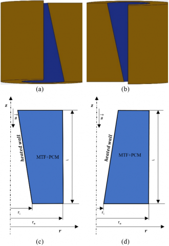
The focus of this paper is to investigate a shell and tube configuration that is vertical and has an internal tube with a non-constant section and considering its external heat losses. The study considers various inclinations of the internal tube, and the space between the external shell and internal tube is filled with a phase change material (PCM) and metal foam. Figures 1(a)-(b) depicts the 3D configuration, where a converging tube is considered in either an up or down position. Figures 1(c)-(d) shows the 2D axisymmetric model that is used for the computational domain. The key geometric parameters of this configuration include L, which is the height of the cylinder and is equal to 100 mm, ri, the internal radius, and re, the external radius, which is equal to 50 mm. The minimum internal radius is equal for each inclination value and its value is 6 mm. The assumption of a constant minimum internal radius is made to arrange the inclination of the internal tube. This assumption allows the volume of the tank to change due to the variation of the inclination angle, while avoiding the interference of the axisymmetric computational domain on the axis of symmetry due to higher inclination angles. The aluminum foam has a porosity of ε=0.95 and a pore density of 20 PPI. The melting process of PCM is analyzed using the enthalpy-porosity method by Voller and Prakash [18].
Figure 1. (a) converging 3D physical model; (b) diverging 3D physical model; (c) converging 2D computational domain; (d) diverging 2D computational domain
The heat transfer between the PCM and metal foam is modeled using the Forchheimer-extended Darcy model under the local thermal non-equilibrium (LTNE) hypothesis [10]. In this model, the PCM is considered the fluid part of the porous media, while the metal foam is considered the solid part. The study assumes a two-dimensional physical model with an unsteady and laminar two-dimensional axisymmetric flow. The Boussinesq approximation is used to model the buoyancy effect in the momentum equation, and the viscous effects in the energy equation are neglected. The PCM is paraffin wax, and its thermal properties are temperature independent. The metal foam is assumed to be isotropic and homogeneous.
This paper examines two different configurations with four distinct inclination angles. The first configuration features a converging section at the top of the shell and tube geometry, while the second has a diverging section in the same position. The analysis applies an isothermal condition to the internal surface of the cylinder, with a selected temperature of 350 K for the internal surface (Tw). The bases of the cylinder are assumed to be adiabatic. The initial temperature of the system is 293 K. In this paper it is considered a heat loss towards the external surface. To model it a heat transfer coefficient is assumed on the external surface for each simulation. The chosen convective heat transfer coefficients are: 0, 0.1, 0.5, 5 W/m2 K. The free stream temperature is assumed 293 K.
In this section the mathematical model of the above physical problem is described. Considering all the assumptions, the governing equations have the following form starting from the Continuity equation [19]:
$\nabla u=0$ (1)
u denotes the velocity vector of the PCM in the liquid phase.
The following momentum equation is referred to the study [19]:
$\begin{align} & \frac{{{\rho }_{p}}}{\varepsilon }\frac{\partial u}{\partial t}+\frac{{{\rho }_{p}}}{{{\varepsilon }^{2}}}u\cdot \nabla u=-\nabla p+\frac{{{\mu }_{p}}}{\varepsilon }{{\nabla }^{2}}u+ \\ & -\frac{{{(1-\beta )}^{2}}}{({{\beta }^{3}}+\omega )}{{A}_{mush}}u+ \\ & -\frac{{{\mu }_{p}}}{K}u-\frac{{{C}_{F}}}{\sqrt{K}}{{\rho }_{p}}u\left| u \right|+{{\rho }_{p}}g\gamma \Delta {{T}_{0}} \\\end{align}$ (2)
In this context, ρp represents the density of PCM and is dependent on temperature, assuming the Boussinesq approximation. μp is the viscosity of the PCM in its liquid phase, and p represents pressure. Amush is a constant termed as the "mushy constant," which has a value of 1×10⁶ kg m−3 s−1. This value was derived from Buonomo et al. [20] paper, which carried out an analysis on this constant. β represents the liquid fraction, and a constant ω is added to prevent division by zero when β is close to zero. Additionally, γ represents the thermal expansion coefficient of the PCM.
The PCM energy equation and the metal foam energy equation must both be solved under the LTNE assumption.
Under the LTNE assumption two energy equations must be solved, the first for the PCM and the second for the metal foam. These equations are [19]:
$\begin{align} & \frac{{{\rho }_{p}}{{c}_{p}}\partial (\varepsilon {{T}_{p}})}{\partial t}+{{\rho }_{p}}{{c}_{p}}u\cdot \nabla {{T}_{p}}={{k}_{eff,p}}{{\nabla }^{2}}{{T}_{p}}+ \\ & -\varepsilon {{\rho }_{p}}{{H}_{L}}\frac{\partial \beta }{\partial t}+{{h}_{sf}}{{a}_{s}}_{f}({{T}_{s}}-{{T}_{f}}) \\\end{align}$ (3)
$\frac{{{\rho }_{s}}{{c}_{s}}\partial \,[(1-\varepsilon ){{T}_{s}}]}{\partial t}={{k}_{eff,s}}{{\nabla }^{2}}{{T}_{s}}-{{h}_{sf}}{{a}_{s}}_{f}({{T}_{s}}-{{T}_{f}})$ (4)
The energy equations incorporate several variables, including ε, which refers to the porosity of the metal foam, and ρp and cp, which denote the density and specific heat of the PCM. The latent heat of the PCM is represented by HL, while time is denoted by t. The effective thermal conductivity keff is determined by the conductivity of the metal foam (keff,s) and the conductivity of the PCM (keff,p). It can be defined using the following equations [21]:
${{k}_{eff,p}}=\varepsilon {{k}_{RT50}}+{{k}_{d}}$ (5)
${{k}_{eff,s}}=0.181\left[ {{(1-\varepsilon )}^{0}}^{.763} \right]\cdot {{k}_{Al}}$ (6)
The symbols kRT50 and kAl represent the conductivity of RT50 and aluminum at a temperature of 293 K. In this paper, the contribution of dispersion thermal conductivity (kd), which increases linearly with velocity as per the correlation provided by Calmidi and Mahajan [22], is ignored due to the very low intensity of the velocity field. It is important to note that kd has a thermal conductivity two orders of magnitude lower than kRT50.
The term hsf refers to the convective heat transfer coefficient, which represents the convective heat transfer between metal foam and PCM. This coefficient is obtained using the Churchill correlation [23], which is implemented with a User-Defined Function in C++, and then used in Ansys-Fluent. On the other hand, the term asf represents the surface area of the metal foam per unit volume and is calculated as per [22]:
${{a}_{sf}}=\frac{3\pi {{d}_{f}}(1-{{e}^{-((1-\varepsilon )/0.04)}})}{\begin{align} & {{(0.59{{d}_{p}})}^{2}} \\\end{align}}$ (7)
In Eq. (2), the porous zone is modeled using the Darcy and Forchheimer laws. These terms account for the pressure losses caused by viscous and inertial effects resulting from the presence of PCM and metal foam, where the permeability of the porous media is denoted by K and the inertial drag factor is denoted by CF. The value of K can be determined using the following equation [22]:
$\frac{K}{{{({{d}_{p}})}^{2}}}=~0.00073{{(1-\varepsilon )}^{-0.224}}{{\left( \frac{{{d}_{f}}}{{{d}_{p}}} \right)}^{-1.11}}$ (8)
The inertial drag factor, CF, is equal to [22]:
${{C}_{F}}=0.00212{{(1-\varepsilon )}^{-0.132}}{{\left( \frac{{{d}_{f}}}{{{d}_{p}}} \right)}^{-}}^{1.63}$ (9)
Both parameters are influenced by the foam ligament diameter, df, and the pore diameter, dp, which describe the structure of the foam. The two parameters are related to each other by the following ratio [22]:
$\frac{d_f}{d_p}=1.18 \sqrt{\frac{(1-\varepsilon)}{3 \pi}}\left(\frac{1}{1-(e)^{-((1-\varepsilon) / 0.04)}}\right)$ (10)
In this paper, the value of dp is obtained from the studies of Calmidi and Mahajan [22], and Bhattacharya et al. [24]. The physical properties of PCM and metal foam used in numerical simulations are presented in Table 1 and Table 2, respectively. Table 1 summarizes the physical properties of aluminum and Paraffin wax RT 50 [25], assuming that the thermal conductivity and specific heat of Paraffin wax remain the same in both liquid and solid phases. Aluminum foam is selected as the porous medium due to its low cost, density, and weight compared to other materials. The parameters of aluminum foam, as reported in Table 2, are obtained following the work of Battacharya et al. [24], with a particular reference to sample 6. The momentum equation introduces a parameter known as the liquid fraction, β, which describes the mixed region of the enthalpy-porosity model and represents the ratio of the liquid volume to the total volume of a cell in the mixed region. The β value varies between 0 and 1 and depends on the local temperature in the cell:
$\left\{ \begin{align} & \beta =0\quad \quad \quad \quad \quad \quad for\ \ \ T<{{T}_{solidus}} \\ & \beta =\frac{T-{{T}_{solidus}}}{{{T}_{liquidus}}-{{T}_{solidus}}}\quad for\ \ \ {{T}_{solidus}}<T<{{T}_{liquidus}} \\ & \beta =1\quad \quad \quad \quad \quad \quad for\ \ \ T>{{T}_{liquidus}} \\\end{align} \right.$ (11)
When the region is entirely solid, the value of β is 0, and vice versa, when the region is entirely liquid, β is 1. In Eq. (11), T represents the local temperature, Tsolidus represents the temperature in the solid phase below which the domain is entirely solid, and Tliquidus represents the temperature in the liquid phase above which the domain is completely liquid. Melting occurs when the temperature falls between Tliquidus and Tsolidus. The enthalpy-porosity method includes a source term in the momentum equations during the melting or solidification phases, accounting for the solid portion of the mixed zone. This solid portion is modeled as a pseudo-porous zone, with the liquid fraction representing the porosity.
Table 1. Thermal properties
|
Properties |
RT 50 |
Aluminum |
|
ρ [kg/m3] |
820 |
2719 |
|
cp [J/kg K] |
2000 |
871 |
|
k [W/m K] |
0.2 |
202.4 |
|
μ [kg/ms] |
0.0038 |
- |
|
γ [W/m K] |
0.0006 |
- |
|
HL [J/kg] |
168000 |
- |
|
Ts [K] |
318 |
- |
|
TL [K] |
324 |
- |
Table 2. Foam parameters
|
PPI |
20 |
|
ε |
0.9546 |
|
df[m] |
0.0003 |
|
dp [m] |
0.0027 |
|
CF |
0.093 |
|
K × 107 [m2] |
1.3 |
|
keff[W/m K] |
3.42 |
The governing equations are solved using the Ansys-Fluent commercial code [26] through numerical methods. The finite volume method (FVM) is employed to discretize and solve the problem. The pressure-velocity coupling and the pressure calculation are solved using the SIMPLEC and PRESTO algorithms, respectively. A time step of 0.2 seconds is chosen for the transient analysis. The convergence errors are assumed to be 10-5 for continuity and momentum equations, and 10-8 for energy equations.
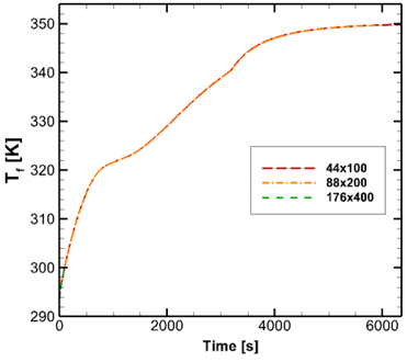
To strike a balance between simulation time and solution accuracy, a mesh comparison is carried out between three different numerical grids: 44×100 (4400 cells), 88×200 (17600 cells), and 176×400 (70400 cells). Figure 2 illustrates the mesh comparison using the average fluid temperature as a comparing variable. Additionally, a comparison of timesteps is presented by considering three values: 0.05 s, 0.2 s, and 0.5 s.
The grid dependence and time step analysis are carried out on the case without an inclination angle. Figure 2 compares the grids in terms of the time evolution of the average fluid temperature. The analysis shows that a grid of 4400 cells strikes the best balance between solution accuracy and processing cost, and it is used for the simulations.
Figure 3 shows the time function of the average fluid temperature inside the domain at different timestep values. A timestep of 0.2 s provides the best compromise between result accuracy and computation load for the numerical simulations.
Figure 2. Grid independence
Figure 3. Timestep independence
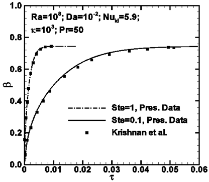
Furthermore, a validation is performed by comparing the data from the numerical model used in this analysis with the results obtained by Krishnan et al. [27], which validates the model. The same boundary and initial conditions are applied to both the model and the data collection, and the same non-dimensional temperature on the domain's midline is monitored at different time steps. Both the numerical data and Krishnan's data are comparable, as shown in Figure 4.
Figure 4. Comparison of the temporal evolution of the average liquid fraction for Ra=108, Nuid=5.9, Pr=50, and Da=10-2 with Krishnan et al.'s results for various Ste values
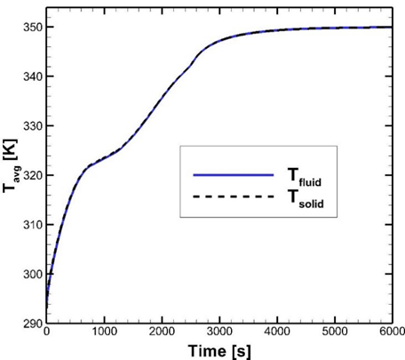
Firstly, a comparison is made between the temperature of the fluid and solid in the porous zone. As shown in Figure 5, the two curves match well, indicating that the Local Thermal Equilibrium (LTE) hypothesis is a valid assumption in this case. Therefore, the corresponding term can be considered negligible in the energy equation.
Figure 5. Time evolution of solid and fluid average temperature
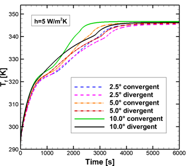
In Figure 6 is shown the average fluid temperature for different configurations and different inclinations angle using the same value of the convective heat transfer coefficient on the external surface. Figure 6 shows that the converging configuration has the shortest charging time. In fact, the temperature at thermal equilibrium is reached faster by converging configurations than by diverging configurations with the same tilt angle. Also, the higher the tilt angle, the faster the TES charges.
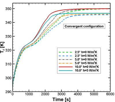
Figure 7 displays the time evolution of the average fluid temperature for the convergent configuration at different inclinations angle comparing the cases without and with heat losses. Figure 7 shows how in configurations where a convective heat transfer coefficient is assigned to the external surface, the temperature at thermal equilibrium decreases compared to the adiabatic case. In addition, since the volume varies as the tilt angle varies, it is seen that the temperature at thermal equilibrium is slightly different as the tilt angle varies for the cases with outward heat loss. For the adiabatic cases, the temperature at thermal equilibrium is the same.
Figure 6. Time evolution of the fluid temperature for different configurations at constant value of the convective heat transfer coefficient
Figure 7. Time evolution of the fluid temperature for the convergent configuration with different inclination angles and for different values of heat transfer coefficient on the external surface
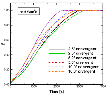
Figure 8 shows the liquid fraction as a function of time for different geometric configurations as the tilt angle changes with a convective heat transfer coefficient value of 5 W/m2K. As previously mentioned, the higher the tilt angle the faster the PCM melts inside the TES. Likewise, the convergent configuration is always faster than the divergent configuration at the same tilt angle. This is due to the greater buoyancy effects present in the convergent configuration.
Figure 8. Time evolution of the average liquid fraction for different geometries
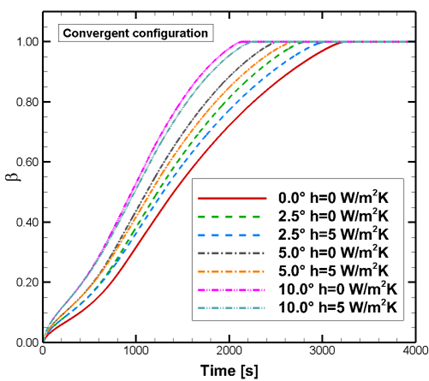
Figure 9 shows the liquid fraction as a function of time for the convergent configuration as the convective heat transfer coefficient changes. In this case, melting is faster in adiabatic configurations than in those with outward heat losses.
Figure 9. Time evolution of the average liquid fraction of the convergent configuration for different heat losses
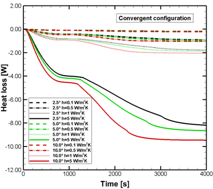
Although the configuration with a tilt angle of 10° is the one with a larger volume, it is still faster than the others. In addition, in Figure 10, it can be seen that the configuration with a tilt angle of 10° is also the one with higher external heat losses. Obviously, the higher the convective heat transfer coefficient, the larger the value of heat loss to the outside.
Figure 10. Time evolution of the heat losses for different inclination angles and different convective heat transfer coefficient
Figure 11 shows the trend of outward heat loss as a function of time considering the same value of convective heat transfer coefficient. Converging and diverging configurations as the angle of inclination changes are shown in this figure.
Figure 11. Time evolution of the heat losses for different configurations and different inclination angles using the same heat transfer coefficient on the external surface
Converging configurations undergo a rapid increase in outward heat loss around 1200 seconds, this effect is surely due to the fact that the melting is totally completed in the upper part of the TES, this results in lower thermal resistance in that region. In addition, for such configurations the effects due to natural convection are more pronounced. Divergent configurations, on the other hand, have a more continuous pattern. Initially, it seems that the heat losses are greater for the diverging configurations, but instead, it is shown that the converging ones have the greatest losses. This is due to the fact that at the top of the TES the thermal resistances of the two configurations are different. For the divergent case, the top section is less than the converging case and therefore melts earlier initially decreasing its thermal resistance. While for the converging case that has larger top section than the diverging case, the such section melts slower, so the thermal resistance is initially higher. When such a section melts totally, the thermal resistance decreases very quickly.
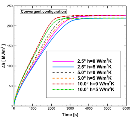
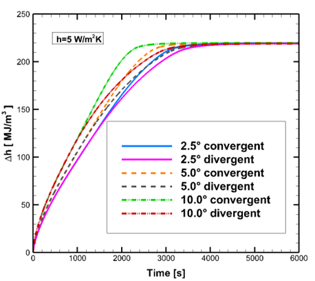
Figures 12 and 13 show the specific enthalpy. It can be seen that by introducing heat losses to the outside, the energy stored by the thermal reservoir decreases. Also, as mentioned earlier, the higher the angle of inclination, the faster the maximum storable energy is reached.
Figure 12. Specific enthalpy for the convergent configuration with different inclination angles and heat transfer coefficient values
Figure 13. Time evolution of the specific enthalpy for different configurations with the same heat transfer coefficient values
In this paper, the analysis related to a shell-and-tube latent heat thermal energy storage was carried out by considering two main configurations as the angle of inclination of the inner pipe of the tank changes. In the first configuration, the inner pipe is convergent at the top of the tank; in the second configuration it is divergent at the top of the TES.
In addition, outward heat losses were considered by assigning different values of the convective heat transfer coefficient on the external surface. The temperature of the external environment is considered equal to 293 K. The results show that although the configuration with the highest angle of inclination, has not only larger volume than the others, but also higher losses, it turns out to be the one with less charging time than the others. In addition, it can be said that the converging configurations have faster charging time than the diverging ones.
Finally, the work is based on the assumption of constant minimum internal radius at different inclinations. This implies a change in volume as the angle of inclination changes. For this reason, a future development will surely be to be able to work at constant volume going to amplify what are the advantages of increasing the tilt angle.
The Authors would like to thank you very much Professor Enrico Lorenzini for the very useful discussion and suggestions on the paper.
This research was partially funded by MIUR (Ministero dell’Istruzione, dell’Università e della Ricerca), grant number PRIN-2017F7KZWS.
|
Acronyms |
||
|
2D |
two dimensional |
|
|
3D |
three dimensional |
|
|
LHTESs |
Latent Heat Thermal Energy Storage System |
|
|
LTE |
Local Thermal Equilibrium |
|
|
LTNE |
Local Thermal non-Equilibrium |
|
|
PCM |
Phase Change Material |
|
|
PPI |
pore per inch |
|
|
TESs |
Thermal Energy Storage System |
|
|
conv |
converging configuration |
|
|
div |
diverging configuration |
|
|
Symbols |
||
|
(ρc)eff |
effective density and specific heat product, J. m-3. K-1 |
|
|
Amush |
mushy zone constant |
|
|
c |
specific heat, J. kg-1.K-1 |
|
|
CF |
inertial drag coefficient |
|
|
df |
fiber diameter, m |
|
|
dp |
pore diameter, m |
|
|
g |
gravitational acceleration, m.s-2 |
|
|
HL |
Latent heat, J. kg-1 |
|
|
h |
specific enthalpy, J. m-3 |
|
|
L |
Height, m |
|
|
K |
Permeability, m2 |
|
|
keff |
effective thermal conductivity, W. m-1. K-1 |
|
|
r |
radial coordinate, m |
|
|
re |
external radius, m |
|
|
ri |
internal radius, m |
|
|
T |
Temperature, K |
|
|
Tliquidus |
liquidus temperature, K |
|
|
Tsolidus |
solidus temperature, K |
|
|
Tw |
wall temperature, K |
|
|
u |
velocity vector, m. s-1 |
|
|
z |
axial coordinate, m |
|
|
Greek symbols |
||
|
Δh |
specific enthalpy variation, J. m-3 |
|
|
β |
liquid fraction |
|
|
γ |
thermal expansion coefficient, K-1 |
|
|
ε |
porosity of metal foam |
|
|
μ |
dynamic viscosity, kg. m-1.s-1 |
|
|
ρ |
density, kg. m-3 |
|
[1] Renewable Energy Agency. (2022). Renewable Capacity Statistics 2022 Statistiques De Capacité Renouvelable 2022 Estadísticas De Capacidad Renovable 2022. Retrieved from www.irena.org.
[2] Jaisatia Varthani, A., Shasthri, S., Baljit, S., Kausalyah, V. (2022). A systematic review of metal foam and heat pipe enhancement in Latent Heat Thermal Energy Storage system. Journal of Energy Storage, 56: 105888. https://doi.org/10.1016/J.EST.2022.105888
[3] Dincer, I., Rosen, M.A. (2010). Thermal Energy Storage: System and Application (2nd ed.). New York: John Wiley & Sons.
[4] Srivastava, M., Sinha, M. (2019). Mathematical modelling for the performance of encapsulated phase change Tess and effect of Stefan’s number. Mathematical Modelling of Engineering Problems, 6(2): 280-284. https://doi.org/ 10.18280/mmep.060216
[5] Khademi, A., Shank, K., Mehrjardi, S.A.A., Tiari, S., Sorrentino, G., Said, Z., Ushak, S. (2022). A brief review on different hybrid methods of enhancement within latent heat storage systems. Journal of Energy Storage, 54: 105362. https://doi.org/10.1016/J.EST. 2022.105362
[6] Kudabayev, R., Suleimenov, U., Ristavletov, R., Kasimov, I., Kambarov, M., Zhangabay, N., Abshenov, K. (2022). Modeling the thermal regime of a room in a building with a thermal energy storage envelope. Mathematical Modelling of Engineering Problems, 9(2): 351-358. https://doi.org/10.18280/mmep.090208
[7] Mabrouk, R., Naji, H., Benim, A.C., Dhahri, H. (2022). A state-of-the-art review on sensible and latent heat thermal energy storage processes in porous media: Mesoscopic Simulation. Applied Sciences (Switzerland), 12(14): 6995. https://doi.org/10.3390/APP12146995
[8] Mao, Q., Liu, N., Peng, L., Liu, D. (2019). A novel shell-and-tube thermal energy storage tank: Modeling and investigations of thermal performance. Applied Thermal Engineering, 159: 113964. https://doi.org/10.1016/J.APPLTHERMALENG.2019.113964
[9] Alhusseny, A., Al-Zurfi, N., Nasser, A., Al-Fatlawi, A., Aljanabi, M. (2020). Impact of using a PCM-metal foam composite on charging/discharging process of bundled-tube LHTES units. International Journal of Heat and Mass Transfer, 150: 119320. https://doi.org/10.1016/J.IJHEATMASSTRANSFER.2020.119320
[10] Karimi, A.R., Siavashi, M., Tahmasbi, M., Norouzi, A.M. (2022). Experimental analysis to improve charge/discharge of thermal energy storage in phase change materials using helical coil and porous metal foam. Journal of Energy Storage, 55: 105759. https://doi.org/10.1016/J.EST.2022.105759
[11] Buonomo, B., Ercole, D., Manca, O., Nardini, S. (2016). Thermal behaviors of latent thermal energy storage system with PCM and aluminum foam. International Journal of Heat and Technology, 34(S2): S359-S364. https://doi.org/10.18280/ijht.34S224
[12] Buonomo, B., Manca, O., Nardini, S., Plomitallo, R.E. (2022). Numerical investigation on shell and tube latent heat thermal energy storage with external heat losses partially filled with metal foam. International Journal of Heat and Technology, 40(4): 895-900. https://doi.org/10.18280/ijht.400405
[13] Hussien, F.M., Hassoon, A.S., Faraj, J.J. (2023). Performance analysis of a triple pipe heat exchanger with phase change materials for thermal storage. International Journal of Heat and Technology, 41(3): 619-628. https://doi.org/10.18280/ijht.410314
[14] Zahid, M.S., Ahmed, N., Qaisrani, M.A., Mahmood, M., Ali, M., Waqas, A., Assadi, M. (2022). Charging and discharging characterization of a novel combined sensible-latent heat thermal energy storage system by experimental investigations for medium temperature applications. Journal of Energy Storage, 55: 105612. https://doi.org/10.1016/J.EST.2022.105612
[15] Li, C., Li, Q., Ge, R. (2022). Enhancement of melting performance in a shell and tube thermal energy storage device under different structures and materials. Applied Thermal Engineering, 214: 118701. https://doi.org/10.1016/J.APPLTHERMALENG.2022.118701
[16] Shafiei Ghazani, A., Gholamzadeh, A. (2023). The effect of conical shell and converging/diverging tube on the charging performance of shell and tube latent heat thermal energy storage system. Journal of Energy Storage, 65: 107262. https://doi.org/10.1016/J.EST.2023.107262
[17] Nie, C., Liu, J., Deng, S. (2021). Effect of geometry modification on the thermal response of composite metal foam/phase change material for thermal energy storage. International Journal of Heat and Mass Transfer, 165: 120652. https://doi.org/10.1016/J.IJHEATMASSTRANSFER.2020.120652
[18] Voller, V.R., Prakash, C. (1987). A fixed grid numerical modelling methodology for convection-diffusion mushy region phase-change problems. International Journal of Heat and Mass Transfer, 30(8): 1709-1719. https://doi.org/10.1016/0017-9310(87)90317-6
[19] Buonomo, B., Ercole, D., Manca, O., Nardini, S. (2018). Numerical investigation on Nano-PCM in aluminum foam in latent thermal energy storages. Modelling, Measurement and Control B, 87(3): 207-212. https://doi.org/10.18280/mmc_b.870313
[20] Buonomo, B., Celik, H., Ercole, D., Manca, O., Mobedi, M. (2019). Numerical study on latent thermal energy storage systems with aluminum foam in local thermal equilibrium. Applied Thermal Engineering, 159: 113980. https://doi.org/10.1016/j.applthermaleng.2019.113980
[21] Calmidi, V.V., Mahajan, R.L. (1999). The effective thermal conductivity of high porosity fibrous metal foams. Journal of Heat Transfer, 121(2): 466-471. https://doi.org/10.1115/1.2826001
[22] Calmidi, V.V., Mahajan, R.L. (2000). Forced convection in high porosity metal foams. Journal of Heat Transfer, 122(3): 557-565. https://doi.org/10.1115/1.1287793
[23] Churchill, S.W., Chu, H.H.S. (1975). Correlating equations for laminar and turbulent free convection from a horizontal cylinder. International Journal of Heat and Mass Transfer, 18(9): 1049-1053. https://doi.org/10.1016/0017-9310(75)90222-7
[24] Bhattacharya, A., Calmidi, V.V., Mahajan, R.L. (2002). Thermophysical properties of high porosity metal foams. International Journal of Heat and Mass Transfer, 45(5): 1017-1031. https://doi.org/10.1016/S0017-9310(01)00220-4
[25] Buonomo, B., di Somma, F., Manca, O., Nardini, S., Plomitallo, R.E. (2021). Numerical investigation on latent thermal energy storage in shell and corrugated internal tube with PCM and metal foam. E3S Web of Conferences, Rome, Italy, p. 03003. https://doi.org/10.1051/e3sconf/202131203003
[26] Ansys-Fluent. (2018). Computational Fluid Dynamic Code Version 19.2 User Guide. Retrieved from https://www.ansys.com/.
[27] Krishnan, S., Murthy, J.Y., Garimella, S.V. (2005). A two-temperature model for solid-liquid phase change in metal foams. Journal of Heat Transfer, 127(9): 995-1004. https://doi.org/10.1115/1.2010494