Mohammed A. Ahmed*![]() | Ibrahim K. Alabdaly
| Ibrahim K. Alabdaly![]() | Saad M. Hatema
| Saad M. Hatema![]() | Maher M. Hussein
| Maher M. Hussein![]()
© 2023 IIETA. This article is published by IIETA and is licensed under the CC BY 4.0 license (http://creativecommons.org/licenses/by/4.0/).
OPEN ACCESS
This study presents a numerical investigation of laminar forced convective flow through a backward-facing step channel integrated with an oval rib, spanning a Reynolds number range of 200-1000. Two-dimensional governing equations of continuity, momentum, and energy were solved in body-fitted coordinates employing the finite volume approach. The investigation sought to elucidate the effects of rib height, rib location, and the Reynolds number on key parameters including the reattachment length, friction factor, total entropy generation, average Nusselt number, and the hydrothermal performance factor. Results demonstrated that both the average Nusselt number and the total entropy generation exhibited an increase with the augmentation of rib height, and conversely, a decrease with the expansion of the step-to-rib distance. In addition, the friction factor was found to increase in proportion to the distance between the rib and the step, and decrease with the rise in rib height, particularly when the Reynolds number exceeded 400. Furthermore, the reattachment length of the primary vortex was observed to increase with the step-to-rib distance and decrease with the rib height. The study concludes that a backward-facing step channel utilizing an oval rib, with a rib height of 0.3 and a rib-to-step distance of 2, delivers an optimal performance factor around 2.1 at a Reynolds number of 400. Therefore, the implementation of the oval rib in a backward-facing step channel is recommended for high thermal performance and compact heat exchanger design.
backward facing step, oval rib, entropy generation, laminar flow, finite volume method
In recent years, the augmentation of heat transfer in heat exchangers and electronic devices has become a focus for researchers, in response to the escalating demands for higher performance from these devices. The utilization of flow over a step or obstacle has been recognized as an effective strategy to enhance the heat transfer rate in thermal devices. These channels, characterized by flow separation and reattachment, are instrumental in improving fluid mixing and the heat transfer rate.
Numerous numerical and experimental studies have been conducted on flow over backward and forward-facing steps [1-3]. Nie and Armaly [4] undertook a numerical investigation into the effect of step height on flow and heat transfer characteristics within a rectangular duct. Their findings indicated an increase in the Nusselt number and friction coefficient in correlation with the step height. A separate numerical study by Abu-Nada [5] examined laminar forced convection over a backward-facing step, applying a second law analysis. The results demonstrated an increase in the total entropy generation in accordance with the Reynolds number and Brinkman number. Further research by Abu-Nada et al. [6] presented a numerical investigation into the influence of blowing and suction on the behavior of thermal and fluid flow over a backward-facing step. Their findings exhibited an increase in the average Nusselt number proportional to Reynolds numbers and the rate of suction bleed. Additionally, the reattachment length was found to increase with the rate of blowing bleed, and decrease with the rate of suction bleed. In another study, Abu-Nada [7] explored the effect of suction and blowing on entropy generation in forced convection flow over a backward-facing step. The numerical results revealed an increase in entropy generation with blowing, and a corresponding decrease with suction.
The boundary conditions of the outflow and inlet channel, and their influence on fluid flow, were investigated by Erturk [8]. The study varied the position of the outflow boundary in different computational domains to examine its impact on results. The findings suggested that the size of recirculating regions exhibited an almost linear growth with the increase in the Reynolds number. In a distinct investigation, Al-Aswadi et al. [9] examined the laminar forced convection flow of nanofluids over a two-dimensional horizontal backward-facing step within a duct. Their results showed the formation of the primary recirculation area following abrupt expansion, which gradually transitioned into a fully developed flow downstream of the reattachment point. They also observed the reattachment point moving downstream and away from the step with an increase in the Reynolds number. Togun et al. [10] reported findings from a numerical investigation of forced convection flow over a backward-facing step, indicating an increase in the average Nusselt number in correlation with the Reynolds number. Similarly, an investigation conducted by Selimefendigil and Öztop [11] into fluid flow, heat transfer, and entropy generation in a backward-facing step revealed that the overall entropy generation increased in line with the Reynolds number. Xie and Xi [12] explored the characteristics of heat transfer and fluid flow over a backward-facing step. Their numerical results showed that as the expansion ratio decreased, the size of the recirculation zone increased. Lastly, Abedalh et al. [13] conducted an experimental study on heat transfer and fluid flow over a backward-facing step in a heated rectangular channel under laminar flow. Their findings revealed an increase in the Nusselt number in correlation with the Reynolds number, while the friction factor decreased as the Reynolds number decreased.
Several researchers have turned their attention to the impact of a corrugated wall or ribs (also known as a turbulator), combined with a backward-facing step channel, on the characteristics of heat transfer and fluid flow. In a study conducted by Nie et al. [14], a numerical investigation was carried out to examine the heat transfer and fluid flow characteristics of a backward-facing step in a rectangular duct with a baffle. It was found that as the distance between the baffle and the inflowing fluid increased, the highest value of the Nusselt number on the stepped wall moved further downstream and closer to the sidewall. Simultaneously, the friction coefficient at the stepped wall decreased with the increasing distance of the baffle from the step. Kumar and Dhiman [15] presented a numerical analysis of heat transfer enhancement in laminar forced convection flow over a backward-facing step in a channel fitted with a circular-cylinder turbulator. The results indicated a heat transfer enhancement of around 155% compared to a stepped channel without a turbulator. In a separate numerical study, Heshmati et al. [16] investigated convection heat transfer over a backward-facing step with an inclined baffle. They observed that the inclined slotted baffle demonstrated the highest heat transfer along the heated wall, accompanied by an increase in pressure drop and skin friction coefficient. Ahmed et al. [17] proposed a numerical investigation of the laminar forced convection flow on a micro-scale backward-facing step with different shapes of turbulators. Their findings showed an increase in the rate of heat transfer and the pressure drop with the use of turbulators in a backward-facing step channel. Boruah et al. [18] conducted a numerical study of the thermo-hydraulic features and entropy generation for mixed convection flow through a backward-facing step channel with baffles. Their examination of the effects of baffle-to-step obstruction space and the number of baffles on fluid flow, heat transfer, and entropy generation characteristics revealed that adding baffles to the lower wall led to a reduction in the reattachment length. They also found that the reattachment length was inversely related to the size of the baffle, and the peak value of the local Nusselt number was observed near the baffle, with these values being dependent on both the size and shape of the baffle. Hilo et al. [19] investigated heat transfer and fluid flow through backward-facing steps combined with different corrugated walls. Their study indicated that the use of a backward-facing step with a corrugated wall led to a significant enhancement in heat transfer, albeit with an increase in the skin friction coefficient. Lastly, Tahseen et al. [20] performed a numerical analysis of laminar fluid flow and heat transfer enhancement using non-rotating adiabatic cylinders in the backward-facing step channel. Their results suggested an increase in heat transfer and a decrease in reattachment length with the use of non-rotating cylinders. Abdollahpour et al. [21] conducted an analysis of the effect of the cylinder on the flow over a backward-facing step channel, finding an increase in the skin friction coefficient in the recirculation zone with the use of a cylinder.
The primary objective of the present study is the comprehensive investigation of the enhancement of heat transfer, the characteristics of fluid flow, and the generation of entropy in a flow through a backward-facing step channel outfitted with an oval rib. The governing equations pertinent to the study have been effectively addressed by deploying the finite volume method. The study methodically explores the impact of varying factors such as the height of the rib, its location, and the Reynolds number. The effects of these variables have been rigorously examined in relation to the reattachment length, the friction factor, the total average entropy generation, the average Nusselt number, and the hydrothermal performance factor. The findings derived from these inquiries are presented and discussed in detail.
2.1 Problem description
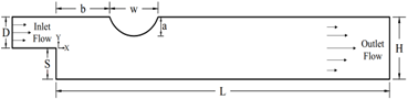
The geometry of current study is shown in Figure 1. It consists of a channel with inlet height of (D), outlet height of (H=10mm), expansion height of (S) and length of (L). One Oval rib, with width of (w) and height of (a), is positioned on the upper surface of the mini-channel at a distance (b) from the inlet. In this investigation, the parameters of geometry are examined in a dimensionless form as follows: L/H=20, w/H=1, S/H=0.5, a/H=0, 0.1, 0.2 and 0.3 as well as b/H=1, 2, and 3. The flow is assumed laminar, steady, incompressible, two-dimensional and no-slip velocity boundary condition at the walls of the channel. The flow at the inlet of channel is assumed to be fully developed. The lower wall of channel is heated with constant wall temperature. The distilled water is used as the working fluid in this investigation.
Figure 1. Geometry of current study
2.2 Governing equations and boundary conditions
Governing equations in terms of body-fitted coordinates in non-dimensional form can be expressed as the study [22, 23]:
Continuity:
∂Uc∂ζ+∂Vc∂η=0 (1)
X-Momentum:
∂∂ζ(UUc)+∂∂η(UVc)=−∂∂ζ(YηP)+∂∂η(YζP)+1Re[∂∂ζ(β11∂U∂ζ)+∂∂η(β22∂U∂η)+∂∂ζ(β12∂U∂η)+∂∂η(β21∂U∂ζ)] (2)
Y-Momentum:
∂∂ζ(VUc)+∂∂η(VVc)=∂∂ζ(XηP)−∂∂η(XζP)+1Re[∂∂ζ(β11∂V∂ζ)+∂∂η(β22∂V∂η)+∂∂ζ(β12∂V∂η)+∂∂η(β21∂V∂ζ)] (3)
Energy:
∂∂ζ(θUc)+∂∂η(θVc)=1RePr[∂∂ζ(β11∂θ∂ζ)+∂∂η(β22∂θ∂η)+∂∂ζ(β12∂θ∂η)+∂∂η(β21∂θ∂ζ)] (4)
where,
Uc=UYη−VXη,Vc=−UYζ+VXζ,J=XζYη−XηYζ,β11=(Y2η+X2η)/J,β22=(X2ζ+Y2ζ)/J,β21=β12=−(XζXη+YζYη)/J (5)
The total average entropy generation equations in the non-dimensional form are presented by the study [24]:
Ntot. =1(Tin ∗+θ)2[(∂θ∂X)2+(∂θ∂Y)2]+Ec⋅Pr(Tin∗+θ)[2{(∂U∂X)2+(∂V∂Y)2}+(∂U∂Y+∂V∂X)2] (6)
The dimensionless parameters that are used in the above equations can be expressed as:
X=xH,Y=yH,U=uuin ,V=vVin,θ=T−TinTw−Tin,P=pρu2in,T∗in=TinTw−Tin,Ec=v2inCp(Tw−Tin) (7)
In this study, the boundary conditions that have been considered can be expressed as follows [25]:
U=12(y−2y2),V=0,θ=1−2y (8a)
∂U∂X=0,∂V∂X=0,∂θ∂X=0 (8b)
U=0,V=0,θ=1 (8c)
U=0,V=0,θ=0 (8d)
The continuity, momentum, and energy equations governing the flow, which expressed in dimensionless form, are converted from Cartesian coordinates to body-fitted coordinates. These equations are then discretized using the finite volume method [26] and solved iteratively using the SIMPLE algorithm [27]. The convection components within the momentum and energy equations have been discretized through the utilization of a second-order upwind scheme. While, the diffusive terms have been discretized using central difference scheme. In this investigation, the computational domain was generated by solving two-dimensional Poisson equations. A configuration of the collocated grid was employed, where all physical variables, including pressure, velocities, and temperature, were stored at the same nodes in the computational domain [28]. Figure 2 shows the computational grid of the present investigation at a/H=0.3 and b/H=1. The CFD code used for simulating the current study is developed using the FORTRAN programming language. To attain convergence of the numerical solution, a convergence standard of 10-5 was employed for all variables.
After solving the above governing equations, the features of the flow and thermal fields should be obtained to calculate the average Nusselt number, friction factor, hydrothermal performance factor and entropy generation. Hence, the local Nusselt number at the lower surface of the mini-channel can be illustrated as follows [29]:
Nux=−∂θ∂Y (9)
The average Nusselt number can be calculated as [30]:
Nuave. =1L∫L0Nuxdx (10)
The thermal-hydraulic performance factor can be determined as [31]:
PEC =(Nuave,with rib Nuave,without rib )/(fwith rib fwithout rib )1/3 (11)
where, f is the friction factor which can be expressed as [30]:
f=ΔPHL2ρnfu2in (12)
The total entropy generation of thermal and friction is defined as [32]:
Nt=1L∫L0Ndx (13)
Figure 2. The computational grid employed in this study
The physical properties of water studied in this investigation are given in Table 1 [25].
Table 1. Physical properties of the present study
|
|
|
k (W/m K) |
α (m2/s) |
|
4179 |
997.1 |
0.613 |
1.47×10⁷ |
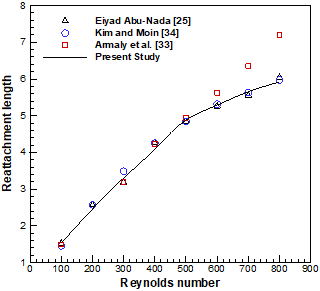
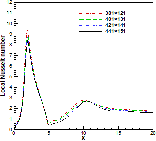
In order to validate the results of present study, the reattachment length of a 2D horizontal backward-facing step was determined and compared with other previous numerical results obtained by Abu-Nada [25], an experimental result of Armaly et al. [33] and numerical results of Kim and Moin [34] at Pr=0.7, and AR=2.0. According to Figure 3, it is noted that results show a high level of agreement. To test the grid independence for the flow over backward facing step using oval rib, the local Nusselt number at the lower wall has been calculated for different grid sizes (381×121, 401×131, 421×141, and 441×151) at Re=1000, a/H=0.3, and b/H=1 as shown in Figure 4. It is found that the grid size 421×141 (i.e., 421 nodes in the x-direction and 141 nodes in the y-direction) can present the grid independence solution which is adopted in the present study.
Figure 3. Comparison the results of current study with the previous numerical and experimental result
Figure 4. Local Nusselt number for different grid sizes at a/H=0.3, b/H=1
5.1 Effects of the rib heights
Figures 5 and 6 present the streamwise velocity and temperature contours, respectively, for fluid flow in backward facing step channel using oval rib with various rib heights at b/H=2 and Re=600. It is found that the rib height has a clear influence on the flow and thermal fields. Looking at velocity contours, it is observed that a recirculation zone (primary vortex) is created downstream of the step on the lower surface of the channel due to the effect of the sudden change in streamwise velocity at the upper corner of the step causes the formation of the adverse pressure gradient. On the other hand, the secondary vortex is created on the upper surface of the channel due to the influence of step on the upper wall. Further, using an oval rib at the upper wall has a significant effect on the primary and secondary vortexes that appear in channel. It is seen that the primary vortex size decrease, while the size of the secondary recirculation increases as the height of the rib increases. As a result, the intensity of recirculation zones increases and the flow becomes more troubled and consequently enhances the fluid mixing in the channel.
Figure 5. Streamwise velocity contours for various rib heights at Re=600 and b/H=2
From the temperature contours, it can be indicated that the increase in rib height leads to a reduction in the thermal boundary layer thickness at the lower-heated wall. This is because the primary vortex size decrease and the reattachment point of this vortex moves in the direction of the step as the rib height increases as a result decrease the thickness of thermal boundary layer. However, the mixing of fluid in the channel will improve with increases the rib height due to the presence and influence of the primary and secondary vortexes which appear in the channel.
Figure 7 shows the reattachment length of the primary recirculation zone versus Reynolds number for various rib height. It is noted that the reattachment length rises with Reynolds number for different value of rib height. This is due to the adverse pressure gradient produced by the sudden expansion. It is also shown that the reattachment length decreases with increasing the height of the rib for all values of Reynolds number because of the influence of the oval rib on the primary vortex created near the step which led to reduce its size with an increase in the rib height, see Figure 4.
Figure 6. Isotherms contours for various rib heights at Re=600 and b/H=2
Figure 7. Effects of the rib heights on reattachment length
The variation of the friction factor with respect to Reynolds number for various ribs height at b/H=2 is shown in Figure 8. It is found that at different rib height, the friction losses decrease as Reynolds number increases up to 400, while it is increased when Reynolds number beyond 400. This is to be expected because the primary vortex size, that created downstream of the step on the lower surface, increases with Reynolds number. Therefore, the additional shear forces on the walls of the channel lead to an increase in the friction factor. Furthermore, results found that when Re>400, the friction losses decreases as the rib height increases. This effect can be attributed to the decrease in both the intensity and size of the primary vortex. (see Figure 4) with increases the rib height and hence decrease the friction factor. In addition, the values of the friction factor at a/H=0 are very close to that at a/H=0.1 over the entire range of Reynolds numbers.
Figure 9 displays the overall average entropy generation versus Reynolds number for various rib height. Results noted that the total entropy generation increases with an increase in Reynolds number at a given rib height due to heightened velocity and temperature gradients. Additionally, the overall average entropy generation also rises with the rib height at a given value of Reynolds number. This happens because of the increase in frictional and thermal irreversibilities caused by the presence of recirculation regions adjacent to the upper and lower surfaces of the channel.
Figure 8. Effects of the rib heights on friction factor
Figure 9. Effects of the rib heights on total average entropy generation
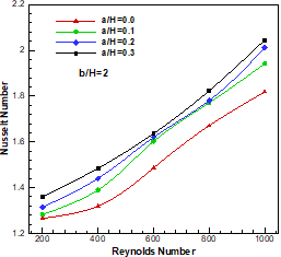
Figure 10 illustrates the relation between Reynolds number and the average Nusselt number for various rib heights at b/H=2. As expected, for all rib heights, it is obvious that the overall Nusselt number rises with an increase in Reynolds number, owing to the rise in temperature gradient at the lower wall as Reynolds number increases. Also, it is detected that the average Nusselt number increases with rib height, especially at a high Reynolds number. This is because enhances the fluid mixing within the core with the hot fluid close to the lower surface of the mini-channel and hence increases the heat transfer enhancement. This trend is similar to the pervious results that reported by Eleiwi et al. [20].
Figure 11 displays the influence of oval rib height on the hydrothermal performance factor (PEC) at b/H=2. Clearly, the performance factor is significantly influenced by the height of the rib. Results indicate that the maximum value of the performance evaluation criterion (PEC) can be achieved at a/H=0.3, whereas the smallest value of PEC is achieved at a/H=0.1. Furthermore, the values of PEC remain greater than unity for all rib height values over the entire range of Reynolds numbers. This indicates that the heat transfer enhancement is more than the rise in friction losses, resulting in an overall positive impact on the performance. The maximum values of PEC about 2.1 at Re=400 and a/H=0.3.
Figure 10. Effects of the rib heights on average Nusselt number
Figure 11. Effects of the rib heights on thermal-hydraulic performance factor (PEC)
In summary, it can be deduced that the backward-facing step channel using an oval rib with a rib height of 0.3 is a suitable choice in terms of heat transfer enhancement and friction factor.
5.2 Effects of the rib locations
The streamwise velocity and temperature contours for fluid flow in backward facing step channel for different rib location at a/H=3 and Re=600 are presented in Figures 12 and 13. It can be shown that from these figures, rib location has a significant influence on the velocity and temperature contours. According to velocity contours, it can be observed that the size of recirculation zone (primary vortex) that appear near the lower surface of channel increase with increase the distance between the step and the rib. While the size of secondary vortex that created on the upper wall of channel decrease as the rib located away (i.e. increase the distance) from the step. In addition, the velocity and thermal boundary thickness at the lower surfece rises with increasing the distance between the oval rib and the step which leads to decrease the rate of heat transfer.
Figure 12. Streamwise velocity contours for different rib locations at Re=600, a/H=0.3
Figure 13. Isotherm contours for various rib locations at Re=600, a/H=0.3
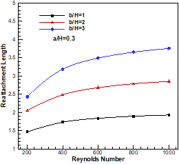
Figure 14. Effects of the rib location on reattachment length
Figure 14 illustrates the variation of the reattachment length of the primary recirculation zone with Reynolds number for various rib locations at a/H=0.3. As expected, for all rib locations, it is noticeable that the reattachment length rises with an increase in Reynolds number. It is seen that the reattachment length increases with the step-to-rib distance increases. This means that the effect of rib on the primary vortex size decrease with rising the value of b/H, see Figure 12, and hence increase the primary vortex size and consequently increase the reattachment length.
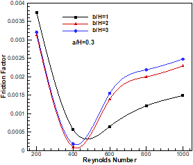
Figure 15 displays the relation between the friction factor and Reynolds number for various distances between the rib and the step at a/H=0.3. It can be noted that the friction factor decreases with an increase in Reynolds number up to 400. This effect because the presence of the secondary and primary recirculation reigns at the upper and the lower surfaces of the channel, respectively. Also, it can be noted that when Re>400, The friction losses increase with an increase in the step-to-rib distance. In addition, when Re<400, it is observed that the maximum friction factor occurs at b/H=1.
Figure 15. Effects of the rib location on friction factor
Figure 16 present the influence of rib location on the overall average entropy generation for different Reynolds numbers at a/H=0.3. In general, the entropy generation increases with an increase in Reynolds number for all rib locations. Also, the entropy generation increases with decreases the space between the rib and the edge of the step. This is because the intensity of recirculation regions increases as the distance decrease and consequently increases the frictional and thermal irrever-sibilities.
Figure 16. Effects of the rib location on total average entropy generation
Figure 17 describes the relation between Nusselt number and Reynolds number for various rib locations at a/H=0.3. As expected, it can be observed that the average Nusselt number increases with an increase in Reynolds number for all rib locations due to increase the temperature gradient with Reynolds number. Additionally, it is showed that the average Nusselt number increases as the distance between the rib and the step decreases. This is because when the location of the rib is closer to the step, the flow become more disturbed and the fluid mixing is improved as well as decrease the thickness of thermal boundary layer and hence increase the rate of heat transfer.
Figure 17. Effects of the rib location on average Nusselt number
Figure 18 presents the variation of the performance factor with Reynolds number for different rib locations. It can be observed that both Reynolds number and rib locations have a significant influence on the performance factor. Overall, the Performance Evaluation Criterion (PEC) remains greater than one for all the rib height values and Re>200. This indicates that the rate of heat transfer enhancement overpowers the increase in friction losses. Furthermore, the highest value of PEC around 2.1 which obtained at b/H=2 and Re=400. It can be concluded that the preferable choice of ribs locations at b/H=2.
Figure 18. Effects of the rib location on thermal-hydraulic performance factor (PEC)
In this paper, laminar forced convective flow through backward facing step channel with oval rib has been numerically investigated over Reynolds range of 200-1000. The influences of rib height, the rib location and Reynolds number on the flow and thermal characteristics are presented and analyzed.
Based on the above results, the following conclusions can be summarized:
Therefore, the backward-facing step channel with an oval rib is theoretically recommended as the ideal design for heat exchangers to achieve the highest thermal performance and a more compact design.
|
a |
rib height (mm) |
|
|
AR |
aspect ratio (H/D) |
|
|
b |
distance between step and rib (mm) |
|
|
CP |
specific heat (J/kg.K) |
|
|
D |
inlet channel height (mm) |
|
|
Ec |
Eckert number |
|
|
f |
friction factor |
|
|
h |
heat transfer coefficients (W/m2.K) |
|
|
H |
outlet channel height (mm) |
|
|
J |
Jacobian of transformation |
|
|
K |
thermal conductivity (W/m.K) |
|
|
L |
channel length (mm) |
|
|
N |
dimensionless entropy generation |
|
|
Nu |
Nusselt number |
|
|
Pr |
Prandtl number |
|
|
P |
pressure (Pa) |
|
|
PEC |
Thermal-hydraulic Performance factor |
|
|
Re |
Reynolds number (Re=ρ uin H/µ) |
|
|
T |
temperature (K) |
|
|
Tin* |
dimensionless reference temperature |
|
|
u, v |
velocity components (m/s) |
|
|
U, V |
dimensionless velocity component |
|
|
W |
Oval rib width (mm) |
|
|
x, y |
2D cartesian coordinates (mm) |
|
|
X, Y |
dimensionless cartesian coordinates |
|
|
Greek symbols |
||
|
ζ, η |
body-fitted coordinates |
|
|
β11, β12 |
transformation coefficients |
|
|
β21, β22 |
transformation coefficients |
|
|
ρ |
density (kg/m3) |
|
|
θ |
non-dimensional temperature |
|
|
Δp |
pressure drop (pa) |
|
|
µ |
dynamic viscosity (N.s/m2) |
|
|
Subscripts |
||
|
ave |
average value |
|
|
f |
base fluid |
|
|
in |
inlet |
|
|
t |
total entropy generation |
|
[1] Goldstein, R.J., Eriksen, V.L., Olson, R.M., Eckert, E.R.G. (1970). Laminar separation, reattachment, and transition of the flow over a downstream-facing step. Journal of Fluids Engineering, 92(4): 732-739. https://doi.org/10.1115/1.3425124
[2] Armaly, B.F., Durst, F., Pereira, J.C.F., Schönung, B. (1983). Experimental and theoretical investigation of backward-facing step flow. Journal of Fluid Mechanics, 127: 473-496. https://doi.org/10.1017/S0022112083002839
[3] Aung, W. (1983). An experimental study of laminar heat transfer downstream of backsteps. ASME Journal of Heat and Mass Transfer, 105(4): 823-829. https://doi.org/10.1115/1.3245668
[4] Nie, J.H., Armaly, B.F. (2002). Three-dimensional convective flow adjacent to backward-facing step-effects of step height. International Journal of Heat and Mass Transfer, 45(12): 2431-2438. https://doi.org/10.1016/S0017-9310(01)00345-3
[5] Abu-Nada, E. (2005). Numerical prediction of entropy generation in separated flows. Entropy, 7(4): 234-252. https://doi.org/10.3390/e7040234
[6] Abu-Nada, E., Al-Sarkhi, A., Akash, B., Al-Hinti, I. (2007). Heat transfer and fluid flow characteristics of separated flows encountered in a backward-facing step under the effect of suction and blowing. ASME Journal of Heat and Mass Transfer, 129(11): 1517-1528. https://doi.org/10.1115/1.2759973
[7] Abu-Nada, E. (2008). Investigation of entropy generation over a backward facing step under bleeding conditions. Energy Conversion and Management, 49(11): 3237-3242. https://doi.org/10.1016/j.enconman.2007.10.031
[8] Erturk, E. (2008). Numerical solutions of 2-D steady incompressible flow over a backward-facing step, Part I: High Reynolds number solutions. Computers & Fluids, 37(6): 633-655. https://doi.org/10.1016/j.com-pfluid.2007.09.003
[9] Al-Aswadi, A.A., Mohammed, H.A., Shuaib, N.H., Campo, A. (2010). Laminar forced convection flow over a backward facing step using nanofluids. International Communications in Heat and Mass Transfer, 37(8): 950-957. https://doi.org/10.1016/j.icheatmasstransfer.2010.06.007
[10] Togun, H., Safaei, M.R., Sadri, R., Kazi, S.N., Badarudin, A., Hooman, K., Sadeghinezhad, E. (2014). Numerical simulation of laminar to turbulent nanofluid flow and heat transfer over a backward-facing step. Applied Mathematics and Computation, 239: 153-170. https://doi.org/10.1016/j.amc.2014.04.051
[11] Selimefendigil, F., Öztop, H.F. (2015). Influence of inclination angle of magnetic field on mixed convection of nanofluid flow over a backward facing step and entropy generation. Advanced Powder Technology, 26(6): 1663-1675. https://doi.org/10.1016/j.apt.2015.10.002
[12] Xie, W.A., Xi, G.N. (2017). Fluid flow and heat transfer characteristics of separation and reattachment flow over a backward-facing step. International Journal of Refrigeration, 74: 177-189. https://doi.org/10.1016/j.ijrefrig.2016.10.006
[13] Abedalh, A.S., Shaalan, Z.A., Yassien, H.N.S. (2021). Mixed convective of hybrid nanofluids flow in a backward-facing step. Case Studies in Thermal Engineering, 25: 100868. https://doi.org/10.1016/j.csite.2021.100868
[14] Nie, J.H., Chen, Y.T., Hsieh, H.T. (2009). Effects of a baffle on separated convection flow adjacent to backward-facing step. International Journal of Thermal Sciences, 48(3): 618-625. https://doi.org/10.1016/j.ijthermalsci.2008.05.015
[15] Kumar, A., Dhiman, A.K. (2012). Effect of a circular cylinder on separated forced convection at a backward-facing step. International Journal of Thermal Sciences, 52: 176-185. https://doi.org/10.1016/j.ijthermalsci.2011.09.014
[16] Heshmati, A., Mohammed, H.A., Darus, A.N. (2014). Mixed convection heat transfer of nanofluids over backward facing step having a slotted baffle. Applied Mathematics and Computation, 240: 368-386. https://doi.org/10.1016/j.amc.2014.04.058
[17] Ahmed, H.E., Kherbeet, A.S., Ahmed, M.I., Salman, B.H. (2018). Heat transfer enhancement of micro-scale backward-facing step channel by using turbulators. International Journal of Heat and Mass Transfer, 126: 963-973. https://doi.org/10.1016/j.ijheatmasstransfer.2018.05.082
[18] Boruah, M.P., Randive, P.R., Pati, S. (2018). Hydrothermal performance and entropy generation analysis for mixed convective flows over a backward facing step channel with baffle. International journal of Heat and Mass Transfer, 125: 525-542. https://doi.org/10.1016/j.ijheatmasstransfer.2018.04.094
[19] Hilo, A.K., Iborra, A.A., Sultan, M.T.H., Hamid, M.F.A. (2020). Effect of corrugated wall combined with backward-facing step channel on fluid flow and heat transfer. Energy, 190: 116294. https://doi.org/10.1016/j.energy.2019.116294
[20] Tahseen, T.A., Eleiwi, M.A., Hameed, A.F. (2020). Numerical study of fluid flow and heat transfer in a backward facing step with three adiabatic circular cylinder. Journal of Advanced Research in Fluid Mechanics and Thermal Sciences, 72(1): 80-93. https://doi.org/10.37934/arfmts.72.1.8093
[21] Abdollahpour, M., Gualtieri, P., Vetsch, D.F., Gualtieri, C. (2023). Numerical study of flow downstream a step with a cylinder part 2: Effect of a cylinder on the flow over the step. Fluids, 8(2): 60. https://doi.org/10.3390/fluids8020060
[22] Alabdaly, I.K., Ahmed, M.A. (2019). Numerical investigation on the heat transfer enhancement using a confined slot impinging jet with nanofluid. Propulsion and Power Research, 8(4): 351-361. https://doi.org/10.1016/j.jppr.2019.06.004
[23] Mohammed, M.K., Ahmed, M.A. (2018). Numerical study on the convective heat transfer of nanofluid flow in channel with trapezoidal baffles. Anbar Journal of Engineering Sciences, 9(1): 185-194. https://doi.org/10.37649/AENGS.2018.145597
[24] Mukhopadhyay, A. (2010). Analysis of entropy generation due to natural convection in square enclosures with multiple discrete heat sources. International Communications in Heat and Mass Transfer, 37(7): 867-872. https://doi.org/10.1016/j.icheatmasstransfer.2010.05.007
[25] Abu-Nada, E. (2008). Application of nanofluids for heat transfer enhancement of separated flows encountered in a backward facing step. International Journal of Heat and Fluid Flow, 29(1): 242-249. https://doi.org/10.1016/j.ijheatfluidflow.2007.07.001
[26] Versteeg, H.K., Malalasekera, W. (2007). An Introduction to Computational Fluid Dynamics: The Finite Volume Method. Pearson Education.
[27] Pletcher, R.H., Tannehill, J.C., Anderson, D. (2012). Computational Fluid Mechanics and Heat Transfer. CRC Press.
[28] Ferziger, J.H., Perić, M., Street, R.L. (2019). Computational Methods for Fluid Dynamics. Springer.
[29] Ahmed, M.A., Shuaib, N.H., Yusoff, M.Z., Al-Falahi, A.H. (2011). Numerical investigations of flow and heat transfer enhancement in a corrugated channel using nanofluid. International Communications in Heat and Mass Transfer, 38(10): 1368-1375. https://doi.org/10.1016/j.icheatmasstransfer.2011.08.013
[30] Ahmed, M.A., Yusoff, M.Z., Ng, K.C., Shuaib, N.H. (2015). Numerical investigations on the turbulent forced convection of nanofluids flow in a triangular-corrugated channel. Case Studies in Thermal Engineering, 6: 212-225. https://doi.org/10.1016/j.csite.2015.10.002
[31] Ahmed, M.A., Yusoff, M.Z., Ng, K.C., Shuaib, N.H. (2015). Numerical investigations on the turbulent forced convection of nanofluids flow in a triangular-corrugated channel. Case Studies in Thermal Engineering, 6: 212-225. https://doi.org/10.1016/j.csite.2015.10.002
[32] Lam, P.A.K., Prakash, K.A. (2015). A numerical investigation of heat transfer and entropy generation during jet impingement cooling of protruding heat sources without and with porous medium. Energy Conversion and Management, 89: 626-643. https://doi.org/10.1016/j.enconman.2014.10.026
[33] Armaly, B.F., Durst, F., Pereira, J.C.F., Schönung, B. (1983). Experimental and theoretical investigation of backward-facing step flow. Journal of Fluid Mechanics, 127: 473-496. https://doi.org/10.1017/S0022112083002839
[34] Kim, J., Moin, P. (1985). Application of a fractional-step method to incompressible Navier-Stokes equations. Journal of Computational Physics, 59(2): 308-323. https://doi.org/10.1016/0021-9991(85)90148-2