Xianjie Di![]() | Yijun Wang
| Yijun Wang![]() | Chunshui Huang*
| Chunshui Huang*![]()
© 2023 IIETA. This article is published by IIETA and is licensed under the CC BY 4.0 license (http://creativecommons.org/licenses/by/4.0/).
OPEN ACCESS
With the rapid progression of urbanisation and the continual refinement of transportation networks, prefabricated box culverts have increasingly attracted attention as modern structural components. Their rapid construction and environmentally friendly characteristics have rendered them a favoured choice within the engineering community. However, under high-temperature conditions, such as in fires or high-temperature industrial processes, concerns remain about the temperature distribution within these culverts and the subsequent impact on joint performance. Although some studies have addressed the temperature distribution and thermal effects associated with these culverts, most have been grounded in theoretical assumptions or have only engaged in preliminary experiments. In this research, an in-depth analysis of the temperature distribution within prefabricated box culverts under high-temperature conditions and the implications for joint performance is undertaken. Advanced finite element analysis tools are utilised for simulations. The findings provide the engineering community with comprehensive and precise reference data, holding significant implications for the design, construction, and maintenance of future prefabricated box culverts.
prefabricated box culverts, elevated temperature environments, temperature distribution, joint performance, finite element analysis
The acceleration of urbanisation worldwide necessitates the urgent refinement of transportation networks. Prefabricated box culverts, a novel structural component, are gaining widespread attention within the engineering domain due to their rapid construction, minimal environmental impact, and significant economic benefits [1-4]. However, the unpredictability of high-temperature scenarios in real-world applications, such as fires and high-temperature industrial processes, places emphasis on the safety and temperature distribution of these culverts [5-7]. Specifically, the joints, a crucial part of the culverts, play a pivotal role in determining the overall safety of the structure under high temperatures. Though some research has touched upon this issue, further exploration in this realm remains essential [8, 9].
Understanding the performance of prefabricated box culverts and their joints under elevated temperatures serves dual purposes. It not only assures structural safety but also provides a scientific basis for engineers during the design, construction, and maintenance phases [10-13]. In events like fires or other high-temperature incidents, the thermal effects and temperature variations of the joints become determinants of the culvert's structural integrity. Hence, a profound understanding of these effects is paramount for enhancing fire prevention measures, averting potential damage due to thermal expansion, and ensuring long-term stability and safety of the prefabricated box culverts [14, 15].
While thermal effects on prefabricated box culverts have been investigated, most studies tend to rely on theoretical assumptions and preliminary experimental data. Common methodologies often presuppose uniform temperature distributions or consider only simplified one-dimensional heat conduction issues. Multi-directional heat conduction effects and the complexity of the joints in real-world applications are frequently overlooked [16-19]. Moreover, research on joint performance under high temperatures is still in its nascent stages, with most relevant studies focusing on ambient or low-temperature environments [20-23].
Addressing these research gaps, this work is segmented into two core sections. Initially, an in-depth examination of the temperature distribution of prefabricated box culvert components under high temperatures was undertaken, especially when factoring in realistic multi-directional heat conduction effects. Through advanced mathematical modelling, multi-directional heat conduction issues were simplified into one-dimensional problems, and precise temperature distribution predictions were obtained. Subsequently, comprehensive simulation analyses of the culvert structure and joint performance under elevated temperatures were conducted, harnessing advanced finite element analysis tools such as ANSYS and Fluent. This comprehensive exploration not only offers invaluable reference data for engineering applications but also establishes a new benchmark for future thermal effect research.
In certain circumstances, the thickness of box culvert components is substantially smaller than other dimensions, such as length and width. Under these conditions, the temperature variation in the direction of thickness might greatly surpass that in other directions, leading to an assumption that heat conduction primarily occurs along the thickness. This study simplifies the heat conduction problem of prefabricated box culvert components under high temperature along the thickness direction into a one-dimensional conduction problem, greatly simplifying the mathematical model and computational process. With this one-dimensional model, only one spatial variable and time variable need consideration, allowing for simpler mathematical tools for solutions without the need for complex finite element software or other numerical methods. Laboratory tests often face size and condition constraints. For smaller components or restricted test conditions, the one-dimensional model along the thickness might be a more appropriate choice.
2.1 Analytical solution of one-dimensional steady-state heat conduction problem
When analysing the one-dimensional steady-state heat conduction problem of prefabricated box culvert components under high temperature, it's pivotal to define the problem's boundaries and initial conditions. Physical properties of the prefabricated box culvert components, such as material type, density, thermal conductivity, and specific heat, need identification. These properties dictate the material's thermal response. If the box culvert material is heterogeneous or composite, the attributes of each layer and their inter-layer interactions should be taken into account. Any additional heat sources, such as solar radiation or nearby equipment, must be identified, and their impacts on the box culvert temperature assessed.
Subsequently, an appropriate heat conduction equation is chosen and relevant boundary conditions applied. For various materials or multi-layered structures, internal thermal resistance or interfacial thermal resistance might require consideration. The one-dimensional steady-state equation remains a simplified model. In practical application, the equation might require modifications based on other influencing factors, such as material anisotropy. Boundary conditions must not only consider the interior and exterior boundaries of the box culvert but also any potential thermal bridges or leaks.
Further, the equation is solved. Numerical methods like the finite difference method or finite element method might offer solutions for complex boundary conditions or varying material properties. When material properties vary with temperature, iterative methods might be required for solutions until satisfactory convergence conditions are met.
Assuming the thermal conductivity of the insulation board and the concrete component are represented by η1 and η2, respectively, and that the temperatures of the high-temperature side gas and the low-temperature side gas are represented by Yd1 and Yd2, respectively. The heat transfer coefficients between the walls and the high and low-temperature gases are given as g1 and g2. Assuming that the surface heat transfer coefficients and material thermal conductivity don't change with temperature variations, the heat transfer process of the prefabricated box culvert components under high temperature can be deemed a one-dimensional steady-state heat transfer process. A numerical simulation of the above analytical process follows.
Initially, the Newton cooling equation, expressed between the high-temperature gas and the insulation board contact wall, is established:
$\Theta=g_1 S\left(Y_{d 1}-Y_{q 1}\right)$ (1)
Thermal conduction within the insulation board can be derived and calculated:
$\Theta=\eta_1 S \frac{Y_{q 1}-Y_{q 2}}{\sigma_1}$ (2)
Moreover, thermal conduction within the concrete component can be determined through the following:
$\Theta=\eta_2 S \frac{Y_{q 2}-Y_{q 3}}{\sigma_2}$ (3)
Similarly, the equation between the right-side concrete component and the low-temperature gas is as follows:
$\Theta=g_2 S\left(Y_{q 3}-Y_{d 2}\right)$ (4)
Under the assumption of steady-state heat transfer, the calculated heat flow is represented by Θ, and if the values calculated in equations 1-4 are consistent, the total thermal resistance is represented by Ej:
$\Theta=\frac{Y_{d 1}-Y_{d 2}}{\left(\frac{1}{g_1}+\frac{\sigma_1}{\eta_1}+\frac{\sigma_2}{\eta_2}+\frac{1}{g_2}\right) \frac{1}{S}}=\frac{Y_{d 1}-Y_{d 2}}{E_j}$ (5)
Assuming the heat transfer coefficient is represented by j, the heat flux density of the prefabricated box culvert component's flat wall per unit area can be further obtained:
$w=\frac{Y_{d 1}-Y_{d 2}}{\left(\frac{1}{g_1}+\frac{\sigma_1}{\eta_1}+\frac{\sigma_2}{\eta_2}+\frac{1}{g_2}\right)}=j\left(Y_{d 1}-Y_{d 2}\right)$ (6)
Upon calculating the heat flux density of the prefabricated box culvert component's flat wall per unit area, other quantities can be computed using this heat flux density.
In practical engineering applications, the thermal conduction analysis of prefabricated box culvert components under high temperature is often much more intricate than the model presented here. Factors such as radiative heat transfer, temperature-dependent thermo-mechanical properties of materials, and contact thermal resistance also need consideration under high temperatures. Radiative heat transfer becomes crucial, especially for materials with high reflectivity or emissivity, wherein radiation might be the dominant heat transfer mechanism. Furthermore, many materials' thermal conductivity, density, and specific heat can change with temperature, potentially affecting thermal behaviour significantly. At interfaces where two different materials come into contact, prominent contact thermal resistance might occur due to surface roughness or material mismatches, impacting heat transfer between the two materials.
For simplicity, clarity, and ease of resolution, engineers often employ assumptions to reduce real-world complexities. If the errors these assumptions introduce remain within acceptable limits, or if certain factors have negligible effects in a specific application, those factors might be disregarded.
2.2 Analytical solution for one-dimensional transient heat conduction
In certain scenarios, when one dimension (such as thickness) is significantly smaller than others (e.g., length and width), this particular dimension can be considered "infinitesimally small", whereas the other dimensions are treated as "infinite". Consequently, only heat conduction along this smaller dimension, in this instance, thickness, needs to be considered, simplifying the problem to one-dimensional. Thus, the transient heat conduction issue of box culvert components under high-temperature conditions was reduced to a one-dimensional problem concerning an infinitely large wall. Should heat conduction in a specific direction of the box culvert component be significantly faster than other directions, primary attention can be allocated to the conduction in that direction. For instance, if the thermal resistance in the direction of the culvert's thickness is less than other directions, the thickness may be the dominant heat conduction pathway.
To analyse the one-dimensional transient heat conduction problem of prefabricated box culvert components under high-temperature conditions, the governing equation for one-dimensional transient heat conduction was initially established based on Fourier's Law. Subsequently, boundary conditions were constructed to depict the thermal exchanges on both sides of the wall. One boundary condition, known as the Dirichlet boundary condition, corresponds to known temperatures on both sides of the wall. Another boundary condition, the Neumann boundary condition, relates to known heat flow or heat flux on both wall surfaces.
For the transient one-dimensional heat conduction issue, solutions can be obtained using the method of separation of variables or the finite difference method. In this study, finite element analysis simulations were predominantly employed. Therefore, the governing equation was discretised and solved using the finite element method. Based on the results of the finite element simulation, temperature distributions in the direction of the culvert component's thickness, and their variations over time, were analysed. Furthermore, sensitivity analyses for various boundary conditions or material properties can be conducted to evaluate their impacts on temperature distribution.
The finite element simulation analysis of temperature distribution in prefabricated box culvert components under high-temperature conditions has been recognised as crucial in design and evaluation. Given the complexity involved and the requirement for specific tools, computations based on ANSYS and Fluent have been selected for this study.
The one-dimensional heat conduction problem of prefabricated box culvert components is more conveniently addressed within the framework of finite element analysis. ANSYS, an extensively employed finite element analysis tool, has been shown to handle such simplified issues effectively. Thermo-physical parameters like thermal conductivity, specific heat capacity, density, and heat transfer coefficients all vary with temperature. ANSYS offers tools and features to manage these variations, ensuring that these parameters' dynamics are accurately considered during the simulation process. Heat transfer under high-temperature conditions encompasses conduction, convection, and radiation. While most finite element software can tackle conduction and convection, radiation computations are more intricate. ANSYS incorporates functionalities to manage radiative heat transfer, rendering it an optimal choice for such applications.
Figure 1. Experimental component pipe joint
Figure 2. Experimental component section joint
Considering the joints involve heat exchange between solids and fluids (such as air), calculations of fluid-solid coupling are indispensable. This is where Fluent plays its role. As a CFD software, Fluent is specifically designed for fluid dynamics and thermal interactions with solid interfaces, making it the prime tool for addressing this particular challenge. Figures 1 and 2 display various joint configurations of the experimental components.
3.1 Construction of the heat conduction equation
The heat conduction equation offers a fundamental physical understanding of the problem. It ensures adherence to basic physical laws during the simulation of temperature propagation, such as Fourier's law. The heat conduction characteristics of various materials under different conditions can be described by this equation, providing theoretical support for practical engineering applications. Furthermore, guidance for the application of the finite element method is also derived from the heat conduction equation. Through the discretisation of the heat conduction equation, continuous physical problems can be transformed into a series of discrete equation sets, which can subsequently be solved within finite element software. This procedure is critical for converting actual physical problems into numerical issues.
When considering the heat conduction question for concrete components, the establishment of the heat conduction equation in finite element analysis is undertaken systematically. Initially, the heat conduction control equation is set up based on Fourier's heat conduction law:
$\vartheta v \frac{\partial Y}{\partial y}=\frac{\partial}{\partial z}\left(\eta(Y) \frac{\partial Y}{\partial z}\right)+\frac{\partial}{\partial t}\left(\eta(Y) \frac{\partial Y}{\partial t}\right)+\frac{\partial}{\partial x}\left(\eta(Y) \frac{\partial Y}{\partial x}\right)$ (7)
Assuming the elemental volume is represented by C, {M}Y=[β/βz,β/βt,β/βx]. Heat flux density is represented by w; the overall heat transfer coefficient is denoted by gd, the temperature of the solid surface by Ya, and the surrounding fluid's temperature by Yn. The temperature's virtual variable is symbolised by σY, the area where heat flux is applied by A2, and the area where convection is applied by A3. Its corresponding equivalent integral form is given by:
$\begin{aligned} & \int\left(\vartheta v \sigma Y\left(\frac{\partial Y}{\partial t}+\{c\}^Y\{M\}^Y\right)+\{M\}^Y \sigma Y\left([F]\{M\}^Y\right)\right) f C=\int \sigma Y w f A_2+\int \sigma Y g_d\left(Y_a-Y_n\right) f A_3\end{aligned}$ (8)
Subsequently, temperature calculations within the element are undertaken. When using the finite element method, the concrete component is discretised into numerous finite element units. Inside each unit, temperature can be approximated using shape functions and nodal temperatures. In this study, nodal temperatures represent the temperature inside the unit, assuming the shape function of the unit is denoted by {B}Y, and the nodal temperature vector of the unit by {Yr}Y, resulting in:
$Y=\{B\}^Y\left\{B_r\right\}^Y$ (9)
Assuming the thermal gradient vector is represented by {β}, [N]={M}Y{B}. The gradient of the temperature can be ascertained by deriving the aforementioned shape function. Based on Fourier's law, combined with the results of the previous equation, the temperature gradient and heat flow values for each element can be further acquired:
$\{\beta\}=\{M\} Y=[N]\{Y r\}$ (10)
Heat flux density describes the heat flow amount passing through a unit area. Supposing the thermal conduction property matrix of the material is represented by [F], combined with the aforementioned heat flow and the geometry of the unit, the heat flux density can be computed based on:
$\left.\{w\}=[F]\{M\} Y=[F][N]\} Y_r\right\}=[F]\{\beta\}$ (11)
By connecting the assumed temperature variation with the integral form of the heat conduction equation, the result is:
$\begin{aligned} & \int \vartheta v\{B\}^Y\{B\} f C\left\{\dot{Y}_r\right\}+\int \vartheta v\{B\}^Y[N] f C\left\{Y_r\right\} +\int[N]^Y[F][N] f C\left\{Y_r\right\}=\int\{B\} w f A_2 +\int Y_n g_d\{B\} f A_3-\int g_d\{B\}^Y\{B\}\left\{Y_r\right\} f A_3\end{aligned}$ (12)
Let [V]=∫ϑv{B}Y{B}fC, [Jl]=∫ϑv{B}Y{cY}[N]fC, [Jf]=∫[B]T[D][B]dV, [Kc]=∫gd{B}Y{B}fA3, {Wd}=∫{B}wfA2, {Wv}=∫Yngd{B}fA3. Simplifying these produces:
$[V]\} \dot{Y}\}+\left(\left[J^l\right]+\left[J^f\right]+\left[J^v\right]\right)\{Y\}=\left\{W^d\right\}+\left\{W^v\right\}$ (13)
Based on the heat conduction equation within each element, a total equation matrix can be integrated for the entire concrete component. This usually includes a stiffness matrix and a load vector. By applying boundary and initial conditions and solving this total equation matrix, the temperature distribution of the entire concrete component can be obtained. Let[V]=∑bu=1=[V],[J]=∑bu=1[Jl,f,v];{W}=∑bu=1[Wd,v]u+{W0}. The total number of units is represented by b, and the heat flow on the applied node is denoted by {W0}, derived from the aforementioned deduction process:
$[V]\{\dot{Y}\}+[J]\{Y\}=\{W\}$ (14)
3.2 Selection of parameters
In finite element simulation analysis of prefabricated box culvert components under high temperatures, a myriad of parameters must be considered to ensure the accuracy of the simulation. These parameters reflect the behaviour of materials during the process of heat conduction. Specifically, these parameters include the thermal conductivity, specific heat capacity, overall heat transfer coefficient, density, and enthalpy of both the concrete components and the insulation boards.
The thermal conductivity of concrete delineates its ability to transmit heat internally. This parameter proves to be pivotal as it directly impacts how heat propagates within the concrete component. For siliceous aggregate concrete, its thermal conductivity is given by:
$\eta=2-0.24\left(\frac{Y}{120}\right)+0.012\left(\frac{Y}{120}\right)^2$ (15)
For calcareous aggregate concrete, the formula for thermal conductivity is:
$\eta=1.6-0.16\left(\frac{Y}{120}\right)+0.008\left(\frac{Y}{120}\right)^2$ (16)
The thermal conductivity of the insulation board dictates its insulating effectiveness. A lower coefficient suggests superior insulating capabilities of the board.
Specific heat capacity of concrete conveys the amount of heat it stores or releases for a unit change in temperature. This influences the rate at which the temperature of the concrete rises under the action of an external heat source. The specific heat capacity of concrete components can be computed using the following equation:
$V(Y)=0.2+\left(\frac{0.1}{850}\right) Y$ (17)
For the insulation board, its specific heat capacity determines its responsiveness to thermal changes.
The overall heat transfer coefficient represents the ability of the concrete component or insulation board surface to exchange heat with its surrounding environment. This coefficient takes into account multiple mechanisms of heat exchange such as convection and radiation. Under high temperatures, heat exchange with the external environment can markedly influence the temperature distribution within the component.
Density of the concrete is related to its heat capacity, influencing its temperature response when subjected to heat input. The variation of the concrete component's density with temperature can be characterised by:
$\vartheta(Y)=2400-0.56 Y$ (18)
The density of the insulation board also impacts its thermal response, especially when considering the thickness of the board and the overall heat conduction.
Enthalpy, a thermodynamic parameter representing the internal energy of materials, is typically employed to describe heat exchange during phase transitions or chemical reactions. At elevated temperatures, should the concrete or insulation board undergo any form of phase transition or chemical reaction, the enthalpy change becomes a critical factor to consider.
Finite element transient temperature field analysis of the prefabricated box culvert test component under high temperatures was carried out using the ANSYS software tool. Fluent modules were utilised to handle the coupled heat transfer issues between fluid and solid. Details of the analysis steps and discussion on temperature distribution results are presented below.
Initially, a three-dimensional model of the box culvert was established in ANSYS, ensuring geometrical shape and size consistency with the actual model. Thermal properties of the concrete and other materials, such as thermal conductivity, density, and specific heat capacity, were then assigned to respective parts of the model. Transient high-temperature boundary conditions were applied to the external surfaces of the box culvert. This included time-temperature curves to emulate temperature variations in actual fire scenarios. The model was further discretised using appropriate mesh sizes and types. Finer mesh sizes were required for regions with significant temperature gradients.
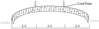
With the Fluent module, heat exchange between fluid and solid, especially in joint areas such as segment joints and pipe joints, was considered. Simulations were run to obtain temperature field distributions under high temperatures. Subsequently, temperature distributions, especially in crucial areas like joints, were evaluated and compared with requirements for fire protection. Figure 3 illustrates the mode of time-load application, marking various load points.
Figure 3. Mode of load application
Simulation results indicated that the outer layer of the prefabricated box culvert reaches elevated temperatures when exposed to high heat, particularly areas in direct contact with the heat source. Due to distinctive structures and materials at joint areas compared to the main body of the culvert, temperature distributions here differ. Depending on joint design and material choices, joints can become hotspots under high temperatures. Inner layers of the box culvert remain relatively cooler, decreasing in temperature as distance from the outer surface increases. Fluid flow within the box culvert can cause rapid temperature spikes in certain areas, especially where flow velocity is high or fluid temperatures are elevated. If fire-resistant measures, such as insulating coatings or boards, are applied, temperature rises in these regions are significantly curtailed.
When fluids and solids come into contact and exchange heat, changes in their temperatures and states ensue. A detailed elucidation of the calculation steps for the coupled heat transfer between fluid and solid is given below. First, interfaces where fluid and solid interact were identified and demarcated. Temperature and pressure on these interfaces became central to the coupled calculations. Fluent was utilised to simulate internal fluid flow, solving the Navier-Stokes equations of the fluid and computing internal velocity, pressure, and temperature distributions. In ANSYS, thermal conduction analysis was performed for the solid part, obtaining internal temperature distributions. Appropriate boundary conditions, such as Robin boundary conditions or other interface-related thermal resistance conditions, were applied to fluid-solid interfaces. Data was iteratively exchanged between fluid and solid until a stable solution, compliant with all boundary and initial conditions, was achieved. Lastly, evaluations were made on heat flows and temperature gradients at the interface, along with other relevant results from the fluid-solid coupling.
For an accurate assessment of fire protection measures, contact thermal resistance effects at joints and other contact points were analysed. An effective insulating material or design can substantially augment contact thermal resistance, thus reducing the rate of heat flow into the structure. Performance of various insulating materials or combinations under high temperatures also warranted evaluation. Some materials may lose their insulating properties at specific temperatures, while others remain relatively stable across a wide temperature range. Further evaluations were made on the time it takes for the prefabricated box culvert to reach its critical temperature, a decisive factor in determining its performance in a fire. Effective fire protection can significantly extend this time. Lastly, the structural integrity and stability under high-temperature influence were assessed, ensuring the structure doesn't prematurely fail during a fire.
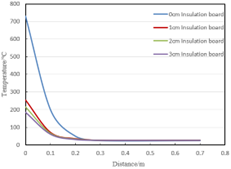
Figure 4. Temperature distribution along the thickness direction under insulation boards of 0cm, 1cm, 2cm, and 3cm
Analysis of the data presented in Figure 4 reveals the temperature distribution at various depths for prefabricated box culvert components beneath insulation boards of different thicknesses. It is evident from the graph that the thickness of the insulation board significantly influences the surface temperature of the prefabricated box culvert components. An increase in the thickness of the insulation board has been observed to markedly reduce the component's surface temperature. For all configurations, temperatures below a depth of 0.3cm remain consistent at 25°C, possibly attributed to the heat conduction properties of the internal material or the convection of internal air. In the absence of insulation, surface temperatures are considerably higher; however, as the depth into the component increases, a more rapid decline in temperature is noted. With the augmentation of insulation board thickness, the rate of temperature decline diminishes, indicating the insulation board's efficacy in impeding further thermal penetration. Among all configurations, the 3cm insulation board yields the lowest surface temperatures, yet considerations of temperature at greater depths within remain imperative for the holistic structural safety.
This analysis underscores the effectiveness of employing insulation boards, as they not only considerably reduce the surface temperature of prefabricated box culvert components but also decelerate the rise in internal temperatures. During the design phase of prefabricated box culverts, thermal considerations are paramount, and selecting insulation boards of appropriate thickness is crucial for ensuring structural safety and durability.
Table 1. Computational conditions
|
Heating Curve |
Computational Construction Type |
Bottom Insulation Protection |
Bottom Insulation Protection (Insulation Partition) |
||||
|
Insulation Material |
Protection Layer Dimensions/m |
Protection Layer Thickness/cm |
Insulation Material |
Protection Layer Dimensions/m |
Protection Layer Thickness/cm |
||
|
HC2h |
Local 1:1 Structure |
Insulation Board |
1.71.7 |
2 |
|
|
|
|
Insulation Board |
1.71.7 |
0, 1, 2 |
|
|
|
||
|
Pipe Section Joint |
Insulation Board |
1.71.7 |
2 |
Insulation Board |
0.91.7 |
2, 3, 4 |
|
|
Pipe Section Joint |
Insulation Board |
1.71.7 |
2 |
Insulation Board |
0.51.7 |
2, 3, 4 |
|
|
RABT2h |
Local 1:1 Structure |
Insulation Board |
1.71.7 |
2 |
|
|
|
|
Insulation Board |
1.71.7 |
0, 1, 2 |
|
|
|
||
|
Pipe Section Joint |
Insulation Board |
1.71.7 |
2 |
Insulation Board |
0.91.7 |
2, 3, 4 |
|
|
Pipe Section Joint |
Insulation Board |
1.71.7 |
2 |
Insulation Board |
0.51.7 |
2, 3, 4 |
|
Table 1 delineates the insulation protection calculations for different parts of the prefabricated box culvert under two distinct temperature-rise curves. This illustrates how the insulation requirements for different parts of the structure vary under diverse fire or high-temperature scenarios. Regardless of the temperature-rise curve, different protective layer thicknesses are considered, aiding in evaluating the influence of varying thicknesses on thermal protection. With the presence of an insulation partition, a broader range of thickness variations is contemplated, aiming for a more detailed assessment of the partition's effect on thermal protection. Performance of the prefabricated box culvert under fire or high-temperature conditions is significantly influenced by the insulation protection's material, size, and thickness. These conditions offer a foundation for thorough research and assessment. When devising and evaluating insulation protection measures for the prefabricated box culvert, these detailed calculation conditions prove imperative, offering a better comprehension of temperature distribution and structural response under distinct circumstances.
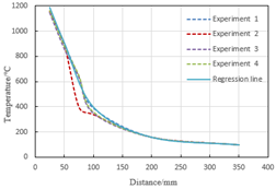
Figure 5(a) showcases data on the maximum temperatures at different distances from the top of the prefabricated box culvert component, derived from four independent experiments and a fitted line. As discerned from the figure, temperatures generally trend downwards with increasing distance, indicating diminishing influence from the heat release zone. Variability exists between experimental data, yet they predominantly outline a similar temperature distribution pattern. Experiment 2 exhibited an anomalously low temperature at a distance of 75 units, warranting further investigation into its cause. The fitted line's data deviates at certain points from the experimental outcomes, particularly at distances of 100 and 200 units. Reassessment of the fitting method or the incorporation of additional data might enhance accuracy. At the 350 unit distance, all experimental outcomes plateau at 100°C, suggesting a weak influence from the heat release area and an approaching stable temperature. Overall, insights into the relationship between the prefabricated box culvert component's top temperature and the distance from the heat release zone emerge, holding significance for understanding the component's high-temperature performance.
Figure 5(b) presents the highest temperature data at different distances for the joint section of the prefabricated box culvert component, sourced from four independent tests and a fitted line. Temperatures at the joint section markedly diminish with increasing distance from the heat release area. Experimental outcomes are relatively concentrated at each point, implying high repeatability in the experiments. The fitted line's temperature is slightly lower or higher than the experimental data at certain points, yet remains proximate for the majority, suggesting its utility in forecasting temperature variations at the joint. At distances of 200 and 350 units, all experimental and fitted line data coincide, indicating extremely stable temperature distribution at these distances. Collectively, the temperature distribution of the prefabricated box culvert component's joint section under high temperatures is considerably influenced by the distance from the heat release zone, offering invaluable insights for design and assessment of joint performance under high temperatures.
(a) Top
(b) Joint
Figure 5. The variation of the highest temperature in the component with the distance from the heat release zone under temperature-rise curves
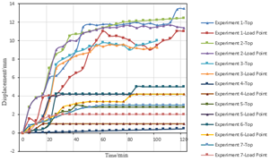
Figure 6. Time-displacement graph for components
Displacement at different time points for the component, with observations made at two monitoring points: the top and the loading point, is depicted in Figure 6. With the passage of time, an increase in displacement at both the top and the loading point is observed, presumably due to external influences or loading. A more pronounced displacement at the top, compared to the loading point, suggests this region might be more susceptible to changes, or the loading point might be subjected to greater constraints. To gain deeper insights into the causes of these displacements and their implications on the performance of the components, further experimental data and comprehensive analyses are deemed necessary.
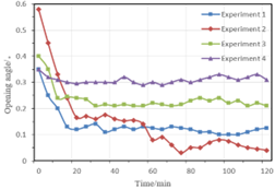
Variations in the opening angles of the component joints over time across different experiments are presented in Figure 7. A general downward trend in the opening angles as time progresses is evident in all experiments, yet the specific rate, magnitude, and stability of decline vary across tests. The most significant decline in opening angle was noticed in Test 2, while Test 4 demonstrated the most stable trend. Variations in these angles can be attributed to the materials used in the joints, their design, or the loading conditions they were exposed to.
Figure 7. Time-opening angle graph for component joints
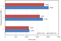
Figure 8. Top external load during concrete edge compression in different joint types
In Figure 8, a comparative analysis of the top external load during concrete edge compression in three different component joints is provided when both straight bolts and bent bolts are used. It can be discerned that for all three joint types, when the concrete edge is in compression, the top external loads are invariably higher for straight bolts than for bent bolts. This indicates the superior load-bearing capacity of straight bolts compared to bent bolts. Based on this data, straight bolts might be the preferred choice if enhancing the top external load-bearing capacity is a primary consideration. Nevertheless, for a holistic decision, other factors such as cost, ease of installation, and material availability must also be taken into account.
The present study was embarked upon to delve into the temperature distribution and joint performance of modular box culverts under high-temperature conditions, with simulations conducted using advanced finite element analysis tools. A comprehensive exploration was carried out on the performance of components under various computational scenarios and experimental conditions. Through the analysis of time-displacement, time-opening angle, and various joint types, the response characteristics of structures under different conditions were elucidated. In the time-displacement experiments, diverse displacement characteristics were exhibited by different tests. Notably, significant displacements were demonstrated in certain tests, while others remained relatively stable. In the time-opening angle experiments, distinctive characteristics for each test were observed, but broadly speaking, the opening angles underwent changes over time. A comparison between straight and bent bolts revealed that straight bolts consistently exhibited a higher external load-bearing capacity across all three types of component joints.
In essence, the findings of this investigation hold significant implications for understanding and predicting the performance of structures under specific conditions and can robustly bolster relevant engineering designs and decisions.
[1] Hata, M., Sato, M., Miyazawa, S. (2022). Experimental study on the application of cementless material with industrial by-products to steam-cured precast concrete products. Materials, 15(21): 7624. https://doi.org/10.3390/ma15217624
[2] Liu, H., Niu, F.J., Niu, Y.H., Yang, X.F. (2014). Study on thermal regime of roadbed–culvert transition section along a high speed railway in seasonally frozen regions. Cold Regions Science and Technology, 106: 216-231. https://doi.org/10.1016/j.coldregions.2014.07.008
[3] Wijaya, A.L., Kajita, S., Tadokoro, Y., Uchino, M., Nakarai, K. (2023). Strength and air permeability of steam-cured expansive concrete: effects of chemical prestress, water-to-binder ratio, and curing condition. Materials and Structures, 56(7): 133. https://doi.org/10.1617/s11527-023-02223-8
[4] Nguyen, H.V., Nakarai, K., Okazaki, A., Karasawa, H., Tadokoro, Y., Tsujino, M. (2019). Applicability of a simplified estimation method to steam-cured expansive concrete. Cement and Concrete Composites, 95: 217-227. https://doi.org/10.1016/j.cemconcomp.2018.11.002
[5] Igawa, H., Eguchi, H., Kitsutaka, Y. (2018). A fundamental study for the self-healing performance of heavyweight concrete. Nippon Kenchiku Gakkai Kozokei Ronbunshu (Online), 83(748): 763-772. http://doi.org/10.3130/aijs.83.763
[6] Larsson-Kråik, P.O. (2012). Managing avalanches using cost–benefit–risk analysis. Proceedings of the Institution of Mechanical Engineers, Part F: Journal of Rail and Rapid Transit, 226(6): 641-649. https://doi.org/10.1177/0954409712447168
[7] Vaslestad, J., Yesuf, G.Y., Johansen, T.H. (2009). Long-term in-situ measurements of concrete culverts with high fills. In Bearing Capacity of Roads, Railways and Airfields: Proceedings of the 8th International Conference on the Bearing Capacity of Roads, Railways and Airfields, Champaign, Illinois, USA, pp. 697-706.
[8] Gong, Y.F., Wu, S.Z., Bi, H.P., Tan, G.J. (2023). Temperature field and frost heaving analysis of prefabricated box culvert based on field monitoring. Jilin Daxue Xuebao (Gongxueban)/Journal of Jilin University (Engineering and Technology Edition).
[9] Koh, T., Hwang, S., Pyo, S., Moon, D., Yoo, H., Lee, D. (2019). Application of low-carbon ecofriendly microwave heat curing technology to concrete structures using general and multicomponent blended binder. Journal of Materials in Civil Engineering, 31(2): 04018385. https://doi.org/10.1061/(ASCE)MT.1943-5533.0002472
[10] Fu, Y.N., He, Z.P. (2012). Concrete crack control technology in Chongqing inch container terminal box letter of application in engineering. Applied Mechanics and Materials, 217: 161-164. https://doi.org/10.4028/www.scientific.net/AMM.217-219.161
[11] Woltman, G., Noel, M., Fam, A. (2017). Experimental and numerical investigations of thermal properties of insulated concrete sandwich panels with fiberglass shear connectors. Energy and Buildings, 145: 22-31. https://doi.org/10.1016/j.enbuild.2017.04.007
[12] Miao, C., Shi, C. (2013). Temperature gradient and its effect on flat steel box girder of long-span suspension bridge. Science China Technological Sciences, 56: 1929-1939. https://doi.org/10.1007/s11431-013-5280-8
[13] Sparkes, J., El Naggar, H., Valsangkar, A. (2019). Compressibility and shear strength properties of tire-derived aggregate mixed with lightweight aggregate. Journal of Pipeline Systems Engineering and Practice, 10(1): 04018031. https://doi.org/10.1061/(ASCE)PS.1949-1204.0000354
[14] Sheng, X.W., Zheng, W.Q., Zhu, Z.H., Yang, Y., Li, S. (2019). Solar radiation time-varying temperature field and temperature effect on small radius curved rigid frame box girder bridge. Jiaotong Yunshu Gongcheng Xuebao/Journal of Traffic and Transportation Engineering, 19(4): 24-34. https://doi.org/10.19818/j.cnki.1671-1637.2019.04.003
[15] Roseen, R.M., Janeski, T.V., Simpson, M., Houle, J.H., Gunderson, J., Ballestero, T.P. (2015). Economic and adaptation benefits of low impact development. In Low Impact Development Technology: Implementation and Economics: LID: Implementation and Economics, pp. 74-92.
[16] Zhang, Y.P., Yang, N., Li, C.X. (2011). Research on temperature field of steel box girder without pavement caused by the solar radiations. Gongcheng Lixue/Engineering Mechanics, 28(6): 156-162.
[17] Lee, J., Son, D., Kwon, S., Ryu, S.W. (2017). Evaluation of methods to prevent soil on a box culvert from freezing-heaving. KSCE Journal of Civil Engineering, 21(3): 752-757. https://doi.org/10.1007/s12205-016-0772-2
[18] Park, J.Y., Sohn, D.S., Lee, J.H., Kim, S.H., Jeong, J.H. (2015). Influence of box culverts on behavior of jointed concrete pavements. Journal of Performance of Constructed Facilities, 29(2): 04014053. https://doi.org/10.1061/(ASCE)CF.1943-5509.0000518
[19] McCraven, S. (2011). Precision precast box culvert performs in New York City. Betonwerk und Fertigteil-Technik/Concrete Plant and Precast Technology, 77(1): 12-19.
[20] Cheng, C., Liu, M., Liao, S. (2021). Measured deformation of pipe-roof during box culvert jacking in soft ground. In IOP Conference Series: Earth and Environmental Science, 719(3): 032047. https://doi.org/10.1088/1755-1315/719/3/032047
[21] Gong, Y.F., Song, J.X., Bi, H.P., Tan, G.J., Hu, G.H., Lin, S.Y. (2020). Static test and finite element analysis of scale model of fabricated box culvert. Jilin Daxue Xuebao (Gongxueban)/Journal of Jilin University (Engineering and Technology Edition), 50(5): 1728-1738. https://doi.org/10.13229/j.cnki.jdxbgxb20190674
[22] Wu, X., Kang, T.H.K., Xia, X., Chen, X.K., Hwang, H.J., Zhou, R. (2019). Behavior and analysis of unsymmetrical double barrel precast concrete box culverts with posttensioning bars. Structural Concrete, 20(4): 1438-1450. https://doi.org/10.1002/suco.201800208
[23] Matsumoto, Y., Yamaguchi, K.,Matsuda, M., Hino, S. (2021). Development of assembly method for large precast box culvert joined by partial prestressing in high-strength rebar. In fib Symposium, 1061-1070.