Layth Thamer Zubairi*![]() | Merdin Danismaz
| Merdin Danismaz![]() | Nabil J. Yasin | Wisam A.M. Al-Shohani
| Nabil J. Yasin | Wisam A.M. Al-Shohani![]()
© 2023 IIETA. This article is published by IIETA and is licensed under the CC BY 4.0 license (http://creativecommons.org/licenses/by/4.0/).
OPEN ACCESS
This study undertakes an experimental and computational evaluation of a dual-flow solar air heater (SAH) equipped with three distinct types of absorber plates: flat, trapezoidal, and U-corrugated. Experiments were conducted under actual outdoor weather conditions in Baghdad, Iraq (33.31ºN, 44.36ºE) during varying days in April and May 2022. The collector, oriented south (surface azimuth angle = zero due south) and tilted at an angle of 30º from the horizontal, was scrutinized under four different airflow rates: 0.0011, 0.0023, 0.0036, and 0.0046 kg/s. Computational simulations of the four absorber plates were performed using ANSYS Fluent software to ascertain and validate thermal efficiencies and performance characteristics. Findings indicate that at an airflow rate of 0.0046 kg/s, the thermal efficiencies of the SAHs with flat, U-corrugated, and trapezoidal plates were 43%, 51%, and 54% respectively. Additionally, a shift from parallel to anti-parallel airflow direction resulted in an increased thermal efficiency from 51% to 56%. It was determined that the optimal configuration was achieved with the U-corrugated plate in an anti-parallel airflow. The average efficiencies at the maximum airflow rate of 0.0046 kg/s were reported as 42.80% for the flat plate, 51.33% for the U-corrugated plate with parallel airflow, 54.38% for the trapezoidal plate with anti-parallel airflow, and 55.53% for the U-corrugated plate with anti-parallel airflow. Finally, a favorable alignment between the experimental and simulated results was observed, with an average discrepancy of 5.7% in thermal efficiency.
solar air heater, dual-flow, flat plate, corrugated plate, trapezoidal plate, computational fluid dynamics, thermal performance
Solar energy, a globally available renewable resource, holds great promise for a clean energy future. One method of harnessing this energy is through solar heaters, which convert solar energy into usable thermal power. However, the poor convection coefficient between the absorber plate's surface and the stream in a solar air heater (SAH) poses a significant challenge. Extensive research has been undertaken to identify the most efficient conventional and modified SAH designs that can suit a variety of needs [1]. Among a plethora of designs, U-corrugated and V-corrugated absorbers are often preferred due to their efficiency in energy capture. Several studies have explored the efficiency of these absorber geometries. Metwally et al. [2] examined a corrugated channel heater alongside five standard configurations and found that the ribbed conduit design outperformed the others, enhancing efficiency by 15%-43% at a solar irradiance of 950 W/m2 and a flow rate of 0.01-0.1 kg/s. Similarly, Liu et al. [3] and Gao et al. [4] reported superior performance of V-corrugated and corrugated absorbers over flat plate heaters. Karim and Hawlader [5] and Choudhury and Garg [6] reached analogous conclusions in their experimental investigations. Certain parameters enhance the efficiency of U-corrugated solar heaters, as demonstrated by Gao et al. [7]. They derived that the height ratio and geometric ratio needed to exceed two and one, respectively, and the inclination angle needed to be less than 40º to minimize heat loss due to natural convection. Furthermore, they found that employing U-corrugated plates increased turbulence, facilitating heat transfer within the airflow duct [4]. Solar heaters with specific design features have also been studied. Forson et al. [8] reported an enhancement in thermal efficiency with an increase in the depth ratios of single-pass solar air heaters (SPSAHs) and double-pass solar air heaters (DPSAHs). Similarly, the introduction of fins to the absorber surface has been shown to significantly improve the performance of DPSAHs [9]. The efficiency of SAHs with V-corrugated absorbers in single- and double-pass modes was found to be superior to that of flat plate SAHs [10]. The influence of solar irradiance and mass flow rates on the efficiency of finned double-pass SAHs was investigated by Fudholi et al. [11]. They discovered that the heater's maximum efficiency was attained at a mass flow rate of 0.09 kg/s and that a solar irradiance of 425-790 W/m2 could provide a potential energy improvement of 740-1,070 W. Further modifications to the design of SAHs have been explored as well. The staggered baffles in a DPSAH was investigated by Ho et al. [12], who reported that the baffled expanded fins induced a turbulent flow pattern and enhanced the thermal efficiency of the DPSAH. A variety of SAH designs have been investigated in the literature, with corrugated and V-corrugated absorbers often emerging as superior due to their efficiency in energy capture. Previous studies have focused on the influence of solar irradiance, mass flow rates, and design modifications on SAH efficiency. Research conducted by EI-Sebaii et al. [13] demonstrated that a V-corrugated double-pass solar air heater (DPSAH) was 11%-14% more efficient than a flat plate DPSAH when the mass flow rate was 0.02 kg/s. This finding was further supported by Liu et al. [14], who revealed that a corrugated SAH was 7% more efficient than a V-grooved SAH across various airflow rates. Hameed et al. [15] presented a novel SAH design and observed that an increase in the mass flow rate led to a decrease in the air-outlet temperature, an increased pressure drop, and enhanced thermal efficiency. In a similar vein, Abuşka and Şevik [16] conducted an experimental study comparing the thermal performance of SAHs using flat and V-grooved aluminum plates, with findings pointing towards the potential for energy, exergy, and environmental enhancements depending on the mass flow rates used. The performance of a cross-corrugated double-pass SAH was explored by Ho et al. [17], who compared it with single-pass and flat plate double-pass configurations. Additionally, Arunkumar et al. [18] analyzed the performance of a modified glazed SAH duct featuring a rectangular duct with a hole in its top surface. Their findings revealed a smaller pressure drop along the absorber channel with increases in height, hole diameter, and number of rows of holes. Ameri et al. [19] investigated the dynamic thermal responsiveness of a regular SAH and a SAH fitted with phase-change materials (PCMs), and found potential for increased efficiency with the use of PCMs. Rajendran et al. [20] conducted a similar investigation using different geometrical layouts over the absorber plate, while El-Said et al. [21] employed a SAH with a tubular swirl flow and a semicircular absorber plate to improve its thermal characteristics.
In this study, both radial and longitudinal fins were incorporated for the evaluation of the proposed semi-circular finned solar air heater (SFSAH). This experimental framework included the examination of three distinct sets of fins, specifically three, four, and five fins. The performance of the proposed SFSAHs was compared with that of a flat plate conduit, as well as a SFSAH devoid of fins. The experimental parameters were carefully controlled, with mass flow rates (m) ranging from 0.01 to 0.50 kg/s, and Reynolds numbers (Re) extending from 7,078 to 35,190. Amara et al. [22] undertook a mathematical and physical investigation of a novel SAH design with a spiral flow channel. Agrawal et al. [23] used SAHs to heat the air, but found the thermal efficiency to be low due to the poor thermal conductivity between the air and the absorber plate. Lastly, Farzan et al. [24] assessed the influence of the recycling method on the performance of SAHs combined with PCMs using computational and experimental studies.
Despite the extensive research efforts dedicated to the study of solar air heaters (SAHs), a critical gap exists in the literature: no study to date has undertaken a comparative analysis of the performance of a dual-flow SAH utilizing various corrugated absorber plates. This study seeks to address this deficiency through an innovative experimental and numerical approach, introducing two key advancements in the field. The first novel aspect of this study involves the implementation of an experimental test on a newly designed geometry of a corrugated absorber plate in a SAH. This experimental design is subsequently validated by numerical modeling, which incorporates three distinct types of corrugated absorber plates (U-corrugated plate with parallel airflow, U-corrugated plate with anti-parallel airflow, and trapezoidal corrugated plate with anti-parallel airflow). This method aims to enhance the convective heat transfer, an integral facet of the SAH's performance. The second innovative element of this research is the experimental comparison of the heat transfer enhancement achieved by the three different types of corrugated absorber plates against a flat plate absorber. This comparison enables a more comprehensive understanding of the thermal efficiency implications of various absorber plate designs.
2.1 Problem description
Full details of the experimental setup are presented in this section. The dual-flow SAHs with different types of plate collectors were designed and used in dimensions. The dual-flow SAHs were tested on different days––in April 2022, these were the 2nd, 3rd, 6th, 18th-20th, 24th, 27th, 28th, 30th, and in May 2022, the 31st––in Baghdad, Iraq (33.31ºN, 44.36ºE). The SAHs were oriented in a southerly direction (surface azimuth angle = zero due south), with a tilt angle of 30° from the horizontal. This was sufficient to heat a room throughout April and May, given Baghdad’s geographical position. The two types of airflow direction studied, where the flow of air was either parallel or anti-parallel to the corrugated geometry of the absorber plate or anti-parallel to the absorber plate, are shown in Figure 1. The choice of collector geometrical parameters, absorbing plate configurations, and airflow rates were based on specifications taken from the literature.
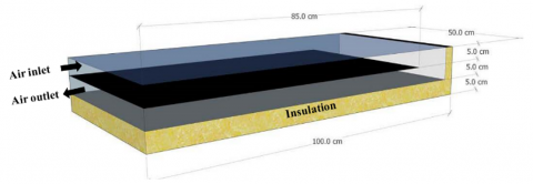
Figure 1. Dual-flow SAHs flat absorber plate
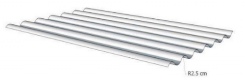
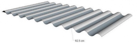
The present study was designed to examine the effects of various flow rates, inlet air temperatures, and solar irradiation levels. The shape of the SAH used was rectangular, 100×50 cm, and 15 cm high, with 5 cm of insulation on the base and 3 cm of wool glass insulation on the side walls. The cover was 4-mm-thick single glass. The entrance and exit of the SAH were built as a trapezoidal shape to maintain uniformity of the inlet and outlet airflow. The top base and lower base of the heater that was created for the experimental setup were 44 cm and 14 cm, respectively, in order to allow for a fully developed airflow. The inlet was a circular duct, 5 cm in diameter. The air blower was fixed in the upper section. A casing was built out of aluminum to enclose all these components. The ideal distance between the absorber plate and the glass cover was 5 cm. Galvanized corrugated panels and an aluminum flat plate, 0.74 mm thick, were used as the absorbing plates. The dimensions of the absorber plate were 85×44 cm. The plate was covered with a thin layer of matt black paint to enable the metal substrate’s emission properties to achieve high overall selectivity or efficiency and to maintain high absorbance. The absorber plate was placed 5 cm from the SAH base. This resulted in the heater being divided into a top duct and a bottom duct. Also, as shown in Figure 2, the ideal distance between the glass cover and the absorber plate was 5 cm, and there should be a 12-cm-long empty zone for pushing air from the top duct to the bottom duct and out of the heater. The overall design specifications for the SAH are summarized in Table 1.
Table 1. Design specifications of the solar air heater
|
Design Specifications |
Value and Units |
|
Collector Title angle |
30 degree |
|
Collector length |
100 cm |
|
Collector width |
50 cm |
|
Collector upper depth |
5 cm |
|
Collector lower depth |
5 cm |
|
Collector material |
Aluminum |
|
Absorber plate type |
U-corrugated plate parallel direction to airflow, U-corrugated plate anti-parallel direction to airflow, and Trapezoidal corrugated plate anti-parallel direction to airflow |
(a) Isometric view
(b) Side view
Figure 2. Thermocouple positions within the dual-flow SAH
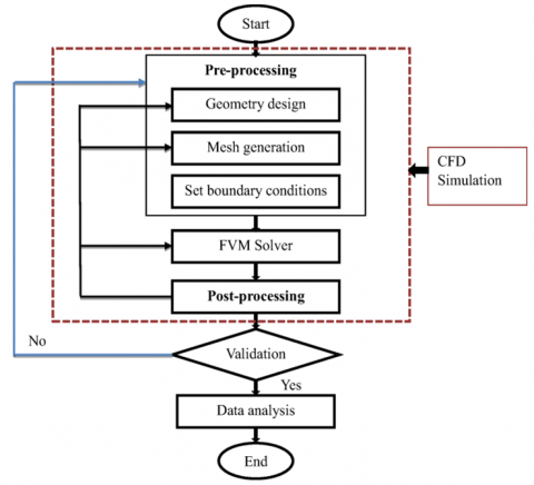
The temperature of the absorber plate was measured at various specified places, and the air temperature inside the SAH was measured simultaneously every 30 min from 07:30 to 17:30. Air was forced to flow into the dual-flow SAH using an air blower with a maximum flow rate of 192 m3/h. The air blower was controlled using an SSR-10VA solid-state relay with a 500-ohm rheostat connected directly to the blower so as to obtain varied mass flow rates. The performance of the dual-flow SAH was examined using mass flow rates varied by 0.0011, 0.0023, 0.0036, and 0.0046 kg/s. The tests were repeated four times for each type of dual-flow SAH on different days. The air and the absorber plate temperatures inside the dual-flow SAH were recorded using K-type thermocouples connected to a temperature meter. Figure 2 shows the thermocouple configuration along the dual-flow SAH. A TES 1333 R data-logging solar meter, with a 2,000-W/m2 range and a 1-W/m2 accuracy, was used to calculate the total solar irradiation. A GM8903 hot-wire anemometer, with a range of 0–30 m/s and an accuracy of ± 0.03 to ± 0.1, was used to measure the air velocity. Figure 3 provides a flowchart for the experimental process.
Figure 3. Experimental processes flow chart
2.2 Data calculation
The desired parameters for the dual-flow SAH absorber plate were established using observed data. The air’s dynamic viscosity, thermal conductivity, specific heat, and density were all determined by taking an average of the air’s entrance and exit temperatures into account. The methodology introduced by Kumar et al. [25] allowed for a definition of the rate at which the heat was transferred:
$\mathrm{Q}=\mathrm{mC}_{\mathrm{p}} \Delta$ (1)
The following equation is used to calculate the SAH duct's air flow velocity:
$V=\frac{m}{\rho W H}$ (2)
The solar air heater's rectangular shape's hydraulic diameter (Dh) is written as follows:
$D_h=\frac{2(W \cdot H)}{(W+H)}$ (3)
The duct of the solar collector Re value given by:
$\operatorname{Re}=\frac{\rho \mathrm{VD}_{\mathrm{h}}}{\mu}$ (4)
The following equation is calculated h value:
$h=\frac{Q}{A_p\left(T_p-T_f\right)}$ (5)
The Nu is then determined using the h and the following equation:
$\mathrm{Nu}=\frac{\mathrm{hD}_{\mathrm{h}}}{\mathrm{k}}$ (6)
The pressure drop (P) measurements recorded over the length of the test section are used to calculate the friction factor as follows:
$f=\frac{2 \Delta P D_h}{4 \rho L V^2}$ (7)
The following equation may be used to determine the collector's thermal efficiency:
$\eta=\frac{\mathrm{mC}_{\mathrm{p}} \Delta \mathrm{T}}{\mathrm{IA}_{\mathrm{p}}}$ (8)
In all honesty, the pressure drop will also rise if a corrugated absorber plate is used in place of a flat absorber plate. Thus, it is crucial to concurrently calculate the rise in heat transfer and pressure drop. The following equation may be used to determine the enhancement of Nu:
$\mathrm{TEF}=\frac{\mathrm{Nu}_{\mathrm{w}} / \mathrm{Nu}_{\mathrm{p}}}{\left(\mathrm{f}_{\mathrm{w}} / \mathrm{f}_{\mathrm{p}}\right)^{0.33}}$ (9)
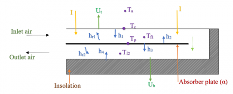
The Figure 4 shows the heat transfer process during solar air heater operation Yousef and Adam [26].
Figure 4. Dual-flow SAHs with thermal network schematic drawing
The mathematical equations of the thermal balance of the dual-flow SAH are studied by Abdullah et al. [27]:
For the heater shelter:
$\mathrm{h}_1\left(\mathrm{~T}_{\mathrm{f} 1}-\mathrm{T}_{\mathrm{c}}\right)+\mathrm{h}_{\mathrm{r} 1}\left(\mathrm{~T}_{\mathrm{p}}-\mathrm{T}_{\mathrm{c}}\right)=\mathrm{U}_{\mathrm{t}}\left(\mathrm{T}_{\mathrm{c}}-\mathrm{T}_{\mathrm{a}}\right)$ (10)
For the upper stream:
$\mathrm{h}_2\left(\mathrm{~T}_{\mathrm{p}}-\mathrm{T}_{\mathrm{f} 1}\right)=\left(\frac{\dot{m} \mathrm{C}_{\mathrm{p}}}{\mathrm{w}}\right)\left(\frac{\mathrm{dT}_{\mathrm{f} 1}}{\mathrm{dx}}\right)+\mathrm{h}_1\left(\mathrm{~T}_{\mathrm{f} 1}-\mathrm{T}_{\mathrm{c}}\right)$ (11)
For absorber plate:
$\begin{gathered}I \tau \alpha=h_{r 1}\left(T_p-T_c\right)+h_2\left(T_p-T_{f 1}\right)+h_3\left(T_p-\right. \left.T_{f 2}\right)+h_{r 2}\left(T_p-T_r\right)\end{gathered}$ (12)
For the lower stream:
$h_3\left(T_p-T_{f 2}\right)=\left(\frac{\dot{m}_p}{w}\right)\left(\frac{d T_{f 1}}{d x}\right)+h_4\left(T_{f 2}-T_r\right)$ (13)
For the lowest plate:
$\mathrm{h}_4\left(\mathrm{~T}_{\mathrm{f} 2}-\mathrm{T}_{\mathrm{r}}\right)+\mathrm{h}_{\mathrm{r} 2}\left(\mathrm{~T}_{\mathrm{p}}-\mathrm{T}_{\mathrm{r}}\right)=\mathrm{U}_{\mathrm{b}}\left(\mathrm{T}_{\mathrm{r}}-\mathrm{T}_{\mathrm{a}}\right)$ (14)
The thermal efficiency Abdullah et al. [27] is given by:
$\eta=\frac{Q_u}{A_c I}$ (15)
The energy gained is given by:
$\mathrm{Q}_{\mathrm{u}}=\dot{\mathrm{m}} \mathrm{C}_{\mathrm{p}}\left(\mathrm{T}_{\text {out }}-\mathrm{T}_{\mathrm{in}}\right)$ (16)
Air mass flow rate:
$\dot{\mathrm{m}}=\rho_{\mathrm{a}} \mathrm{V}_{\mathrm{a}} \mathrm{A}_{\text {duct }}$ (17)
The correlations shown in Table 2 suggest that the physical characteristics of air change linearly with temperature. According to Eqs. (10)-(17), the temperatures used in these relationships are averages.
Table 2. Design specifications of the solar air heater
|
Parameters |
Equations |
Reference |
|
Specific heat |
$\begin{gathered}C_p=1.0057+ 0.000066(T-27)\end{gathered}$ |
Rasham and Alaskari [28] |
|
Density |
$\begin{gathered}\rho=1.1774- 0.00359(T-27)\end{gathered}$ |
Rasham and Alaskari [28] |
|
Thermal conductivity |
$\begin{gathered}\mathrm{k}=0.02624- 0.0000758(\mathrm{~T}-27)\end{gathered}$ |
Rasham and Alaskari [28] |
|
Viscosity |
$\mu=[1.983-0.00184(T-27)] \times 10^{-5}$ |
Rasham and Alaskari [28] |
2.3 Uncertainty analysis
Uncertainty can be divided into two groups––direct measurement ($\delta$T, $\delta$P, $\delta$I, and $\delta$U) and indirect measurement ($\delta$Ac, $\delta$m, $\delta$ρ, and $\delta$η). If a parameter is computed using certain measured quantities, then uncertainty in the measurement of ‘y’ was given as in Acır et al. [29], where $\delta$x1, $\delta$x2, $\delta$x3, ..., $\delta$xn were the possible errors in measurements of x1, x2, x3, ..., xn. $\delta$y is known as the absolute uncertainty.
$\delta y=\left[\left(\frac{\partial y}{\partial x_1} \partial x_1\right)^2+\left(\frac{\partial y}{\partial x_2} \partial x_2\right)^2+\left(\frac{\partial y}{\partial x_3} \partial x_3\right)^2+\cdots\left(\frac{\partial y}{\partial x_n} \partial x_n\right)^2\right]$ (18)
where, $\delta$x1, $\delta$x2, $\delta$x3, ..., $\delta$xn were the possible errors in measurements of x1, x2, x3, ..., xn. $\delta$y is known as absolute uncertainty.
Table 3. Uncertainty specifications
|
Parameter |
Unit |
Uncertainty ($\delta$) |
|
Inlet temperature of collector |
℃ |
±0.12 |
|
outlet temperature of collector |
℃ |
±0.12 |
|
Absorber temperature |
℃ |
±0.12 |
|
Ambient temperature |
℃ |
±0.12 |
|
Air velocity |
m/s |
±0.04 |
|
Time |
min |
±0.11 |
|
Solar radiation |
W/m2 |
±1.33 |
In this study, the uncertainty values for the derivative parameters (rate of heat transfer, h, Re, friction factor, Nu, and η) were estimated using Eqs. (19)-(24), with the calculated values given in Table 3.
$u_Q=\sqrt{\left(\frac{\Delta m}{m}\right)^2+\left(\frac{\Delta c p}{c p}\right)^2+\left(\frac{\Delta T}{T}\right)^2}$ (19)
$u_h=\sqrt{\left(\frac{\Delta Q}{Q}\right)^2+\left(\frac{\Delta A}{A}\right)^2+\left(\frac{\Delta T_{L M T D}}{T_{L M T D}}\right)^2}$ (20)
$u_{R e}=\sqrt{\left(\frac{\Delta \rho}{\rho}\right)^2+\left(\frac{\Delta u}{u}\right)^2+\left(\frac{\Delta \mu}{\mu}\right)^2+\left(\frac{\Delta D_h}{D_h}\right)^2}$ (21)
$u_f=\sqrt{\left(\frac{\Delta \Delta p}{\Delta p}\right)^2+\left(\frac{\Delta \rho}{\rho}\right)^2+\left(\frac{\Delta u}{u}\right)^2+\left(\frac{\Delta D_h}{D_h}\right)^2+\left(\frac{\Delta L}{L}\right)^2}$ (22)
$u_{N u}=\sqrt{\left(\frac{\Delta h}{\Delta h}\right)^2+\left(\frac{\Delta D_h}{D_h}\right)^2+\left(\frac{\Delta k}{k}\right)^2}$ (23)
$u_\eta=\sqrt{\left(\frac{\Delta Q}{\Delta Q}\right)^2+\left(\frac{\Delta A}{A}\right)^2+\left(\frac{\Delta I}{I}\right)^2}$ (24)
3.1 Geometry description
The shape and physical domain of the dual-flow SAH used in the simulation were designed using SOLIDWORKS 2018 software, as shown in Figure 5. Three distinct types of absorber plates (flat, U-corrugated, and trapezoidal corrugated) and various flow orientations were used in the fabrication and testing of the SAH (Table 4).
3.2 Boundary conditions
ANSYS Fluent and ANSYS 2020 R2 software was used to simulate the dual-flow SAH. For the numerical simulation of the SAH, the boundary conditions were those presented in Figure 6, which also shows the geometry and boundary state of a model of a standard dual-flow SAH. The mass air input flow was set to vary by 0.001, 0.0023, 0.0036, and 0.0046 kg/s at a constant inlet air temperature (Tin=22℃), and the default outlet pressure (P=0 pa) was set for the duct’s exit. The top surface of the duct was fixed with a continuous flow of solar heat, with a solar irradiance intensity of I=900 W/m2. The SAH’s other walls were kept in place as insulated walls. The temperature was determined from the numerical results for the outlet airflow and absorber plate. The physical properties of the absorber plates and the insulation are presented in Table 5.
Table 4. Types of absorber plates
|
Model |
Configuration |
|
Flat absorber plate |
|
|
U-corrugated plate parallel direction to airflow |
|
|
U-corrugated plate anti-parallel direction to airflow |
|
|
Trapezoidal corrugated plate anti-parallel direction to airflow |
Table 5. Physical properties of absorber plates and insulation
|
Item |
(K) W/m.K |
(ρ) Kg/m3 |
(Cp) J/Kg.K |
α |
(ε) |
Ref |
|
Flat plate (Aluminum) |
217 |
2707 |
887 |
0.94 |
0.09 |
Sreenivaslu et al. [30] |
|
Corrugated plate (Galvanized iron) |
204.2 |
7870 |
896 |
0.91 |
0.8 |
Sreenivaslu et al. [30] |
|
Glass wool |
0.0372 |
200 |
670 |
- |
- |
Sreenivaslu et al. [30] |
|
Glass |
0.8 |
2500 |
840 |
0.05 |
0.8 |
Ovando Chacon et al. [31] |
Figure 5. Schematic of dual-flow SAHs flat absorber plate
Figure 6. Present problem boundary conditions
The following summarized boundary conditions:
3.3 Governing equations
The conservation of mass, momentum, and energy (Navier–Stokes) equations explain fluid movement and heat. The following kinds of turbulent and incompressible flow are described by these equations [32, 33].
Conservation of Mass:
$\frac{\partial}{\partial t}(\rho)+\frac{\partial}{\partial x}(\rho u)+\frac{\partial}{\partial y}(\rho v)=0$ (25)
Conservation of Momentum:
$\begin{gathered}\rho\left(\frac{\partial \mathrm{u}}{\partial \mathrm{t}}+u \frac{\partial \mathrm{u}}{\partial \mathrm{x}}+\mathrm{v} \frac{\partial \mathrm{u}}{\partial \mathrm{y}}+\mathrm{w} \frac{\partial \mathrm{u}}{\partial \mathrm{y}}\right)=-\frac{\partial \mathrm{p}}{\partial \mathrm{x}}+\mu_{\text {eff }}\left(\frac{\partial^2 \mathrm{u}}{\partial \mathrm{x}^2}+\right. \left.\frac{\partial^2 \mathrm{u}}{\partial \mathrm{y}^2}+\frac{\partial^2 \mathrm{u}}{\partial \mathrm{z}^2}\right)+\mathrm{S}_{\mathrm{u}}\end{gathered}$ (26)
$\begin{gathered}\rho\left(\frac{\partial \mathrm{v}}{\partial \mathrm{t}}+u \frac{\partial \mathrm{v}}{\partial \mathrm{x}}+\mathrm{v} \frac{\partial \mathrm{v}}{\partial \mathrm{y}}+\mathrm{w} \frac{\partial \mathrm{v}}{\partial \mathrm{y}}\right)=-\frac{\partial \mathrm{p}}{\partial \mathrm{y}}+\mu_{e f f}\left(\frac{\partial^2 \mathrm{v}}{\partial \mathrm{x}^2}+\right. \left.\frac{\partial^2 \mathrm{v}}{\partial \mathrm{y}^2}+\frac{\partial^2 \mathrm{v}}{\partial \mathrm{z}^2}\right)+\mathrm{S}_{\mathrm{v}}\end{gathered}$ (27)
$\begin{gathered}\rho\left(\frac{\partial \mathrm{w}}{\partial \mathrm{t}}+u \frac{\partial \mathrm{w}}{\partial \mathrm{x}}+\mathrm{v} \frac{\partial \mathrm{w}}{\partial \mathrm{y}}+\mathrm{w} \frac{\partial \mathrm{w}}{\partial \mathrm{y}}\right)=-\frac{\partial \mathrm{p}}{\partial \mathrm{z}}+\mu_{e f f}\left(\frac{\partial^2 \mathrm{w}}{\partial \mathrm{x}^2}+\right. \left.\frac{\partial^2 \mathrm{w}}{\partial \mathrm{y}^2}+\frac{\partial^2 \mathrm{w}}{\partial \mathrm{z}^2}\right)+\mathrm{S}_{\mathrm{u}}\end{gathered}$ (28)
Energy equation:
$\begin{gathered}\frac{\partial \mathrm{T}}{\partial \mathrm{t}}+\frac{\partial \mathrm{uT}}{\partial \mathrm{x}}+\frac{\partial \mathrm{vT}}{\partial \mathrm{y}}+\frac{\partial \mathrm{wT}}{\partial \mathrm{z}}=\frac{1}{\rho} \frac{\partial}{\partial \mathrm{x}}\left[\Gamma_{\mathrm{eff}} \frac{\partial \mathrm{T}}{\partial \mathrm{x}}\right]+ \\ \frac{1}{\rho} \frac{\partial}{\partial \mathrm{y}}\left[\Gamma_{\mathrm{eff}} \frac{\partial \mathrm{T}}{\partial \mathrm{y}}\right]+\frac{1}{\rho} \frac{\partial}{\partial \mathrm{z}}\left[\Gamma_{\mathrm{eff}} \frac{\partial \mathrm{T}}{\partial \mathrm{z}}\right]\end{gathered}$ (29)
For good prediction of air movement and contaminant dispersion in SAH, a suitable turbulence model needs to be selected from the various existing models. The two-equation renormalized group standard k-ε turbulence model was implemented to predict the turbulence air flow in the SAH. The standard k-ε turbulence model can be expressed as:
Turbulent kinetic energy (k):
$\frac{\partial \mathrm{k}}{\partial \mathrm{t}}+\frac{\partial \mathrm{uk}}{\partial \mathrm{x}}+\frac{\partial \mathrm{vk}}{\partial \mathrm{y}}+\frac{\partial \mathrm{wk}}{\partial \mathrm{z}}=\frac{1}{\rho} \frac{\partial}{\partial \mathrm{x}}\left[\left(\mu_{e f f}+\frac{\mu_{\mathrm{t}}}{\sigma_{\mathrm{k}}}\right) \frac{\partial \mathrm{k}}{\partial \mathrm{x}}\right]+$$\frac{1}{\rho} \frac{\partial}{\partial \mathrm{y}}\left[\left(\mu_{e f f}+\frac{\mu_{\mathrm{t}}}{\sigma_{\mathrm{k}}}\right) \frac{\partial \mathrm{k}}{\partial \mathrm{y}}\right]+\frac{1}{\rho} \frac{\partial}{\partial \mathrm{z}}\left[\left(\mu_{e f f} \mu+\frac{\mu_{\mathrm{t}}}{\sigma_{\mathrm{k}}}\right) \frac{\partial \mathrm{k}}{\partial \mathrm{z}}\right] \frac{1}{\rho}\left(\mathrm{G}_{\mathrm{k}}+\mathrm{G}_{\mathrm{b}}\right)-\varepsilon$ (30)
Dissipation rate $(\varepsilon)$:
$\frac{\partial \varepsilon}{\partial \mathrm{t}}+\frac{\partial \mathrm{u} \varepsilon}{\partial \mathrm{x}}+\frac{\partial \mathrm{v} \varepsilon}{\partial \mathrm{y}}+\frac{\partial \mathrm{w} \varepsilon}{\partial \mathrm{z}}=\frac{1}{\rho} \frac{\partial}{\partial \mathrm{x}}\left[\left(\mu_{e f f}+\frac{\mu_{\mathrm{t}}}{\sigma_{\varepsilon}}\right) \frac{\partial \varepsilon}{\partial \mathrm{x}}\right]+$
$\frac{1}{\rho} \frac{\partial}{\partial y}\left[\left(\mu_{e f f}+\frac{\mu_{\mathrm{t}}}{\sigma_{\varepsilon}}\right) \frac{\partial \varepsilon}{\partial y}\right]+\frac{1}{\rho} \frac{\partial}{\partial z}\left[\left(\mu_{e f f}+\frac{\mu_{\mathrm{t}}}{\sigma_{\varepsilon}}\right) \frac{\partial \varepsilon}{\partial \mathrm{z}}\right]+$
$C_1 \frac{\varepsilon}{\rho k}\left(G_k+C_3 G_b\right)-C_2 \frac{\varepsilon^2}{k} 2$ (31)
where:
$\mu_{\mathrm{eff}}$ Effective viscosity coefficient
$\mu_{\mathrm{eff}}=\mu+\mu_{\mathrm{t}}$ (32)
$\Gamma_{\text {eff }}$ Effective diffusion coefficient
$\Gamma_{\mathrm{eff}}=\frac{\mu}{p_{\mathrm{r}}}+\frac{\mu_{\mathrm{t}}}{\sigma_{\mathrm{t}}}$ (33)
$\mu_{\mathrm{t}}$ Turbulent viscosity
$\mu_{\mathrm{t}}=\rho \mathrm{C}_\mu \frac{\mathrm{k}^2}{\varepsilon}$ (34)
$\mathrm{G}_{\mathrm{k}}$ kinetic energy generation by shear
$\mathrm{G}_{\mathrm{k}}=\mu_{\mathrm{t}}\left(2\left[\left(\frac{\partial \mathrm{u}}{\partial \mathrm{x}}\right)^2+\left(\frac{\partial \mathrm{v}}{\partial \mathrm{y}}\right)^2\right]+\left(\frac{\partial \mathrm{u}}{\partial \mathrm{y}}+\frac{\partial \mathrm{v}}{\partial \mathrm{x}}\right)^2\right)$ (35)
$\mathrm{G}_{\mathrm{b}}$ kinetic energy generation by buoyancy
$\mathrm{G}_{\mathrm{b}}=\frac{\mu_{\mathrm{t}}}{\sigma_{\mathrm{t}}} \frac{\partial \mathrm{T}}{\partial \mathrm{y}} \mathrm{g} \beta$ (36)
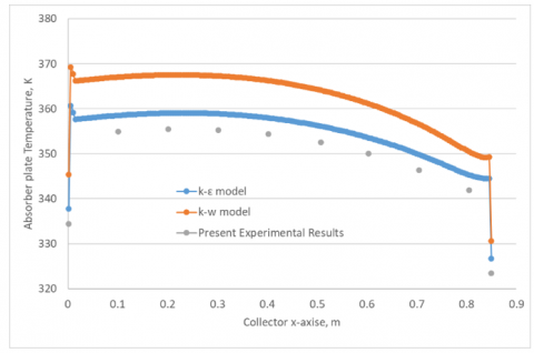
where, $\mathrm{C}_\mu$ represents a large Re flow value for an empirical constant as shown in Table 6. The working fluid/air creates a homogeneous heat flux on the absorber wall and has a Prandtl number of 0.7. To validate the chosen turbulence model, k-e was used with the k-w and experimental results, as shown in Figure 7, which also shows that the k-e model was the closest to the experimental results.
Table 6. Values of constants in the (k-ε) models
|
$\mathbf{C}_\mu$ |
$\mathrm{C}_1$ |
$\mathrm{C}_2$ |
$\mathrm{C}_3$ |
$\boldsymbol{\sigma}_{\varepsilon}$ |
$\sigma_k$ |
|
0.09 |
1.44 |
192 |
1.0 |
1.3 |
1.0 |
Figure 7. Validate the chosen turbulence model k-e with the k-w and experimental results
3.4 Mesh generation and independence study
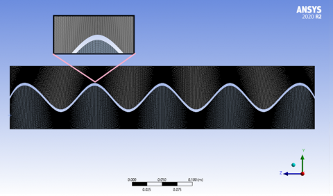
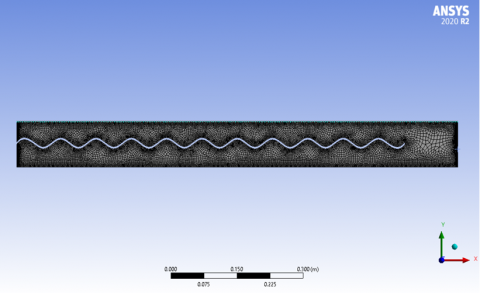
To build the computational domain, a mesh was generated using ANSYS Fluent Workbench and 2020 R2 to develop the mesh files. The air space filling the upward and downward stream of the SAH was modeled using a tetrahedral mesh architecture, as shown in Figure 8. There were 1,946,385 nodes in the x-, y-, and z-axes. The dual-flow SAH mesh was in one segment.
(a) Flat absorber plate
(b) U-corrugated plate parallel direction to airflow
(c) U-corrugated plate anti-parallel direction
(d) Trapezoidal corrugated plate
Figure 8. Computational domain mesh of the dual-flow SAH cavity model
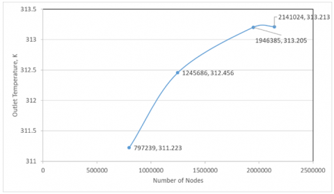
For the grid independence study of the three-dimensional (3-D) simulations, four meshes (coarse, medium, fine, and finer) were assessed, their characteristics summarized in Table 7. A block strategy for each component of the loop was adopted, with the mesh specifications being tested. The near-wall cell size was aimed at y+<1, with a near-wall clustering of cells and an expansion toward the central region (ratio = 1.06). A mesh sensitivity analysis was performed by comparing the outlet temperature profile that was computed and drawn using the numbers from the nodes. These results, from four different grids, are shown in Figure 9. The mesh with 1,946,385 finite volumes was chosen for the subsequent simulations because this grid control volume was considered sufficiently acceptable in terms of accuracy and computational cost for further comparisons.
Table 7. Characteristics of all the 2-D meshes considered for the dual-flow SAH cavity
|
No. |
Mesh Type |
Nodes |
Element |
|
1 |
Coarse |
797239.3 |
748405.6 |
|
2 |
Medium |
1245686 |
1169383 |
|
3 |
Fine |
1946385 |
1827162 |
|
4 |
Finer |
2141024 |
2009878 |
Figure 9. Grid independence study of the 3-D simulations
Figure 10. Numerical solution will present in flow chart
3.5 Numerical solution
The computational domain’s 3-D mesh was exported to the ANSYS Fluent Workbench 2020 R2 software and the numerical solution is presented in the flowchart in Figure 10. The SIMPLE algorithm used the inlet and outlet pressure boundary conditions in this program. When the momentum, energy, and mass for each simulated case were evaluated, the residuals fell below 10-7. In addition, the momentum and pressure estimations were changed by the under-relaxation values of 0.30 and 0.70, respectively, to increase the convergence rate of the model. The energy and density were kept at their default values. To simplify the numerical solution, the following assumptions were applied:
4.1 Experimental results
The major goal of the current study was to establish and quantify improvements in the thermal efficiency of a dual-flow SAH by applying the novel design of a corrugated absorber plate because thermal efficiency is frequently utilized to assess the efficacy of SAHs. The average thermal efficiency was evaluated and described in terms of the solar irradiation and the air mass flow rate. Additionally, experimental measurements of efficiency, energy gained, absorber plate temperature, and temperature difference (ΔT=TO-Ti) were made for various ambient temperatures. The solar radiation values varied from 50 to 895 W/m2 with varying mass flow rates of 0.001, 0.0023, 0.0036, and 0.0046 kg/s of inlet airflow.
Figures 11-15 show a plot of the estimated efficiency, temperature difference, energy gained, and absorber plate temperature for the dual-flow SAH against various mass flow rates and times of day. It can be seen that, when the mass flow rate rose, the efficiency, energy acquired, and amount of heat transferred increased. However, the temperature of the absorber plate fell, but not the outlet air.
Figure 11. Temperature difference with a time of day for U-corrugated plate anti-parallel to airflow dual-flow SAH at different mass flow rate
Due to the high SAH temperature and greater heat loss via the glass and the SAH outlet, it was assumed that the SAH operating at reasonably high flow rates would be more effective with a slight rise in SAH temperature. The temperature differential (ΔT=TO-Ti) for all of the mass flow changed steadily, decreasing from 1:00 pm to 5:00 pm, with the temperature increasing to its highest value at midday and subsequently decreasing at night. At the same mass flow rate, the ΔT was highest for the U-corrugated plate with anti-parallel airflow in the dual-flow SAH model than the other types. When the U-corrugated plate with anti-parallel airflow model was employed to generate DPSAH airflow, the airflow generated more vortices along the plate, increasing the temperature in comparison to the flat plate absorber.
Figure 12. Comparing energy gained for four types of dual-flow SAH at 0.0046 kg/s
The ΔT of the U-corrugated plate with anti-parallel airflow was larger than for all the other dual-flow SAHs. For example, the highest ΔTs of 42.9, 44.5, 51.3, and 45.7℃ occurred at 11:00 am for the flat absorber plate, U-corrugated plate with parallel airflow, U-corrugated plate with anti-parallel airflow, and trapezoidal corrugated plate with anti-parallel airflow, respectively. Due to the high turbulence flow and heat transfer, the U-corrugated plate with anti-parallel airflow was the best.
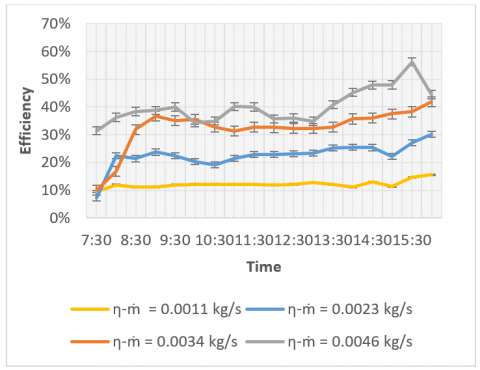
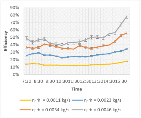
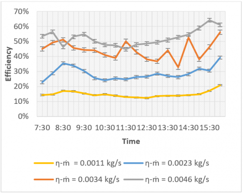
Figure 11 illustrates the temperature differences for the U-corrugated plate with anti-parallel airflow DPSAH at four mass flow rates, and the maximum ΔT values obtained (51, 45.7, 44.5, and 42.9℃). The curves in Figure 11 demonstrate an improvement in the daily difference in air temperature for the U-corrugated plate with parallel, trapezoidal corrugated plate with anti-parallel airflow, and U-corrugated plate with anti-parallel airflow dual-flow SAHs over the flat plate dual-flow SAH at the same flow rate due to the corrugation, which increases the heat transfer area. Additionally, the corrugation decreases the dead zones in the SAH, increases turbulence, and enhances airflow over the absorber plate. Compared to other varieties of dual-flow SAH, the temperature differences for the U-corrugated plate with anti-parallel airflow (maximal turbulence) were larger. The output air temperature was also impacted by the mass flow rate. As a result, there was an inverse relationship between the mass flow rate and the exit air temperature. When the mass flow rate increased, the temperature disparities narrowed. Also, the data demonstrate that the energy obtained first climbed from the lowest amount until midday, at which point it peaked, and then steadily fell until nightfall. The curves exhibit the same pattern of behavior, reaching their maximum values at noon as the mass flow rate increases and the energy gained also increases. By comparing all four models of the dual-flow SAH plotted in Figure 12, it can be seen that the maximum energy gained occurred at noon, being about 199.12 W for the U-corrugated plate with anti-parallel airflow at a mass flow rate of 0.0046 kg/s, whereas it was 192.34, 173.88, and 159.51 W for the trapezoidal corrugated plate with anti-parallel airflow, U-corrugated plate with parallel airflow, and flat plate, respectively. The hourly efficiency (η) at varying mass flow rates of 0.0011, 0.0023, 0.0034, and 0.0046 kg/s is illustrated in Figure 12(a)-(d) for the four types of dual-flow SAH models, respectively. Based on the value of the efficiency (η) indicated in Figure 13, the efficiency (η) started with a modest value and then improved somewhat over the day until reaching its maximum value at the end of the day. In addition, the efficiency of the dual-flow SAH with the U-corrugated plate with parallel airflow was higher than that of the flat plate, as shown in Figure 13(a) and (b) because the corrugation increases the heat transfer coefficient and surface area and extends the airflow pathway by forming new airflow channels between the corrugation. The efficiency of the trapezoidal corrugated SAH was higher than that of the flat plate and U-corrugated plate with parallel airflow, as shown by the comparison between the flat plate and both the corrugated plate and trapezoidal corrugated plate in Figure 13(a)-(c). This is because the air flowing over the trapezoidal corrugated absorber plate generated vortice turbulence on the plate, which improved the heat transfer coefficient. Due to this, we utilized the U-corrugated plate with anti-parallel airflow to compare the thermal performance. The efficiency of the U-corrugated plate with anti-parallel airflow was greater than in the flat plate and the two other types, as illustrated by the comparison in Figure 13(a)-(d). Due to the anti-parallel airflow over the U-corrugated plate, which improved the h, there was an increase in the heat transfer between the absorber plate and the air flowing over and below the absorber plate, thus increasing the thermal efficiency of the dual-flow SAH.
The results presented in Figures 11-15 show that the values vary over time in the graphs due to the temperature of the test area and the temperature difference being the greatest due to the high radiation in the afternoon. Therefore, during these hours (11.30-13.30), the energy gain was the highest. The highest energy gain was measured as 200 W at 13.00 at the lowest flow rate and with a temperature difference of 47℃. Despite the temperature being high, the decrease in radiation in cloudy and shadow situations reduced the energy gain.
(a) flat plate dual-flow SAH
(b) U-corrugated plate parallel to airflow dual-flow SAH
(c) trapezoidal corrugated plate anti-parallel to airflow dual-flow SAH
(d) U-corrugated plate anti-parallel to airflow dual-flow SAH
Figure 13. Hourly efficiency (η) for four types of dual-flow SAH at four mass flow rates
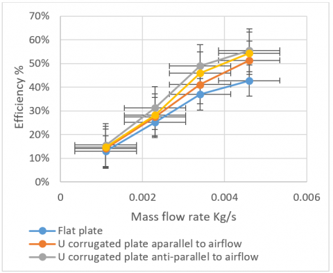
Figure 14 illustrates the average efficiencies for the four types of dual-flow SAH studied. The flat plate dual-flow SAH average efficiencies at the four different airflow rates (0.0011-0.0046 kg/s) were 12.94%, 25.26%, 37.05%, and 42.80%, respectively. For the U-corrugated plate with parallel airflow dual-flow SAH, these values were 14.20%, 27.55%, 41.09%, and 51.33%, respectively, for the trapezoidal corrugated plate with anti-parallel airflow dual-flow SAH they were 14.67%, 28.21%, 45.94%, and 54.38%, respectively, and for the U-corrugated plate with anti-parallel airflow dual-flow SAH, they were 15.57%, 31.22%, 48.95%, and 55.53%, respectively. The U-corrugated plate with anti-parallel airflow, the trapezoidal plate with anti-parallel airflow, and the U-corrugated plate with parallel airflow were the best absorbent plates when compared to the typical flat plate absorbency. The highest average for the U-corrugated plate with anti-parallel airflow was 55.53% due to the increase in turbulence, excellent airflow over the absorber plate, and increased heat transfer area.
Figure 14. Average thermal efficiency for four types of dual-flow SAH at four mas flow rates
Figure 15. Average absorber plate temperature for four types of dual-flow SAH at a mass flow rate 0.0046 kg/s
The average efficiency increased for the four types of dual-flow SAH as the mass flow rate increased from 0.0011 to 0.0046 kg/s. Increasing the turbulence intensity caused the efficiency to rise noticeably when the air-mass flow rate was increased from 0.0011 to 0.0046 kg/s. Figure 15 shows that the maximum average absorber plate temperature at noon was 99℃ for the U-corrugated plate with anti-parallel airflow type at a mass flow rate of 0.0046 kg/s, whereas it was 94.48, 78.34, and 71.78℃ for the trapezoidal corrugated plate with anti-parallel airflow, U-corrugated plate with parallel airflow, and flat plate, respectively.
At midday, the most energy obtained for the four types of dual-flow SAHs—flat plate, U-corrugated plate will parallel airflow, trapezoidal corrugated plate with anti-parallel airflow, and U-corrugated plate with anti-parallel airflow-was 159.51, 173.88, 192.34 W, and 199.12 W, respectively. It is evident that the mass flow rate and the energy acquired are closely correlated, meaning that, as the mass flow rate increases, so does the energy gained.
The U-corrugated plate with anti-parallel airflow dual-flow SAH experienced higher temperature variations than the other types at the same mass flow rate. Owing to the increased vorticity along the plate caused by the airflow and the larger surface area for heat transfer, the temperature increased. The highest temperature for the U-corrugated plate with parallel airflow was 51℃ at midday, while it was 47.4, 48.2, and 48.5℃ at the same mass flow rate for the flat plate, U-corrugated plate with anti-parallel airflow, and trapezoidal plate.
The output air temperature was impacted by the mass flow rate. As a result, there was an inverse relationship between the mass flow rate and the outlet air temperature. When the mass flow rate increased, the temperature differences narrowed.
The maximum absorber plate temperatures for the flat plate, U-corrugated plate with parallel airflow, trapezoidal corrugated plate with anti-parallel airflow, and U-corrugated plate with anti-parallel airflow at the mass flow rate of 0.00411 kg/s were 98.76, 94.72, 102.1, and 100.5℃, respectively. During the day, the average absorber plate temperature was higher than the outlet air temperature. The key findings, trends, main outcomes, and takeaways from the study are summarized in Table 8.
Table 8. Summarized of the absorber plates results
|
Model |
Enhancement |
|||
|
∆T (℃) |
Energy Gained (W) |
η (%) |
Absorber Plate Temperature (°C) |
|
|
Flat absorber plate |
51 |
156 |
42.80% |
98.76, |
|
U-corrugated plate parallel direction to airflow |
45.7 |
163 |
51.33% |
94.72 |
|
U-corrugated plate anti-parallel direction to airflow |
44.5 |
193 |
55.53% |
100.5 |
|
Trapezoidal corrugated plate anti-parallel direction to airflow |
42.9 |
187 |
54.38% |
102.1 |
4.2 Numerical results
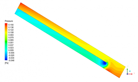
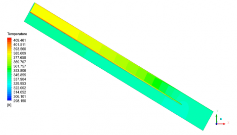
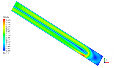
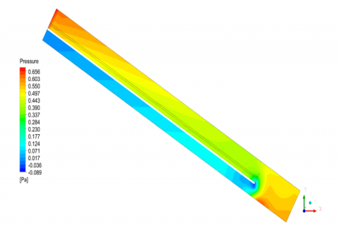
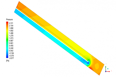
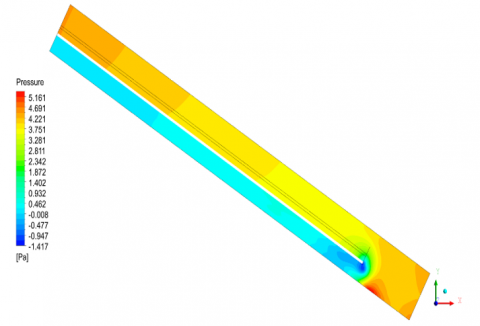
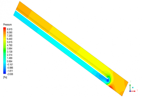
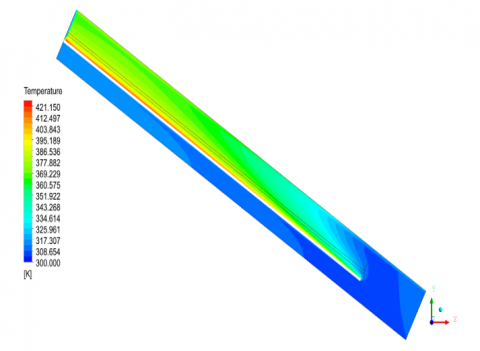
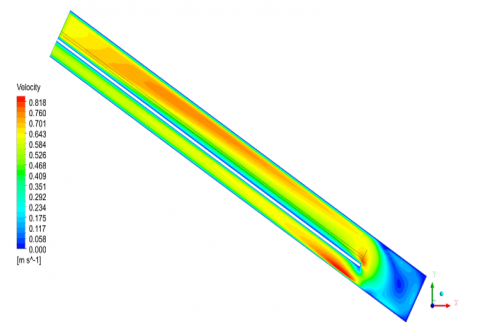
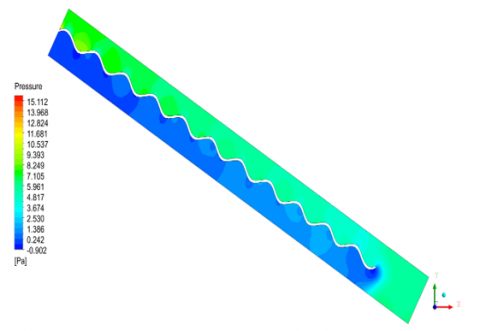
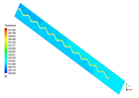
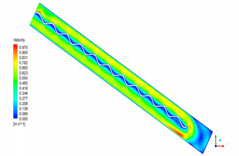
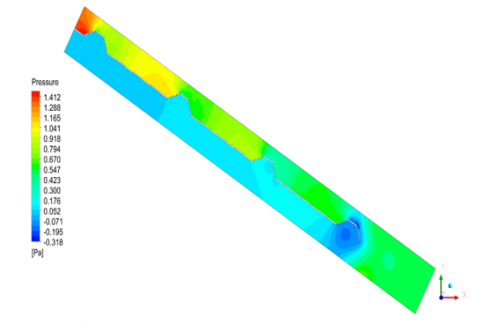
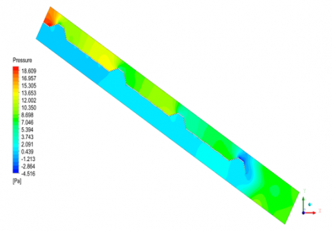
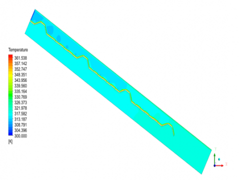
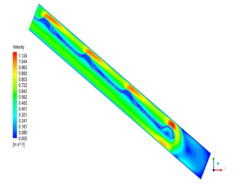
The numerical results for the pressure, temperature, and velocity of the flat plate absorber are plotted in Figures 16-18, and for the U-corrugated plate with anti-parallel airflow in Figures 19-21. The airflow rate increased by 0.0011 to 0.0046 kg/s and the pressure drop increased from 0.047 to 0.157 Pa under the same conditions at 21:00, but rose from 0.041 to 0.150 Pa under the same conditions at 16:00. The highest mass flow rate was the maximum pressure region located in the top zone of the SAH. As can be seen in Figure 17, the results show that the most extreme temperature on the whole absorber dropped with increasing air mass flow rate, but rose with increasing daytime hour, from 09:00 to 12:00. The highest velocity in Figure 18 is in the upper channel of the SAH, and this increased with a rise in air mass flow rate and an increase in daytime hour, from 09:00 to 12:00, although it decreased with increasing time, from 12:00 to 16:00, lowering the solar radiation heat flux. By using the U-corrugated plate with parallel airflow, the pressure would increase from 0.150 to 8.841 Pa at an airflow rate of 0.0046 kg/s and at 16:00. The maximum temperature also decreased, from 89.84 to 56.56℃. The maximum velocity for the U-corrugated plate with parallel airflow was found to be 3.422 m/s, compared with the maximum speed of the flat plate of 0.463 m/s, which resulted from an increase in the momentum of the airflow from the U-corrugated plate with parallel airflow. The maximum absorber temperature was focused on the upper region of the U-corrugated plate with parallel airflow, and it increased here due to the projection of the solar radiation in this region compared with the flat plate absorber.
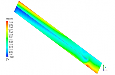
Figure 16. Pressure contours in the flat plate dual-flow SAH at noon at 0.0046 kg/s
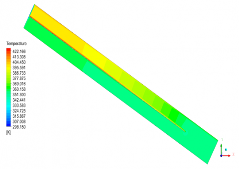
Figure 17. Temperature contours in the flat plate dual-flow SAH at noon at 0.0046 kg/s
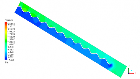
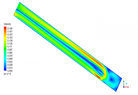
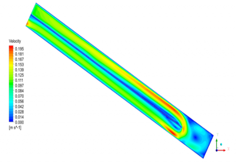
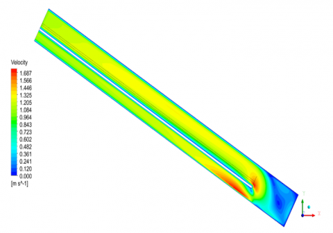
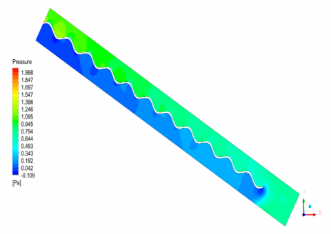
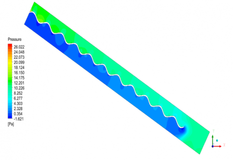
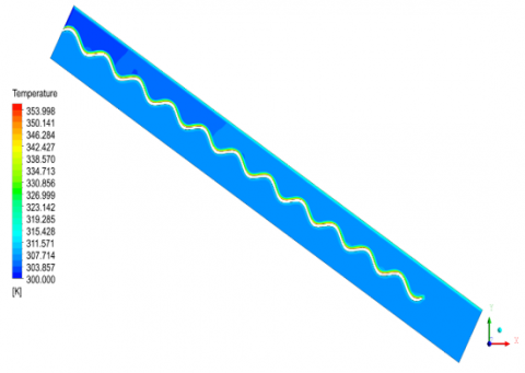
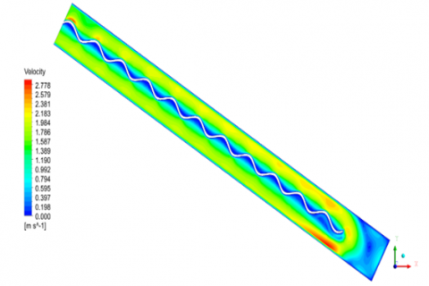
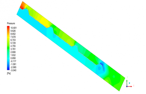
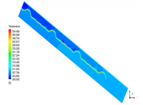
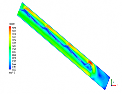
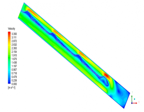
Figure 19 displays the results of the pressure distribution, which increased from 0.150 to 25.664 Pa at an airflow rate of 0.0046 kg/s and at 16:00 as a result of the U-corrugated plate with anti-parallel airflow. When the U-corrugated plate was used in the anti-parallel direction to the airflow of 0.0046 kg/s and at 16:00, the maximum temperature dropped from 89.84 to 55.15℃, as can be seen in Figure 20. However, Figure 21 indicates that the maximum velocity for the U-corrugated plate with anti-parallel airflow was 3.662 m/s, as opposed to the maximum velocity of the flat plate, which was 0.463 m/s at an airflow rate 0.0046 kg/s and at 16:00, which is due to the increasing momentum of the airflow over the U-corrugated plate with anti-parallel airflow.
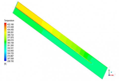
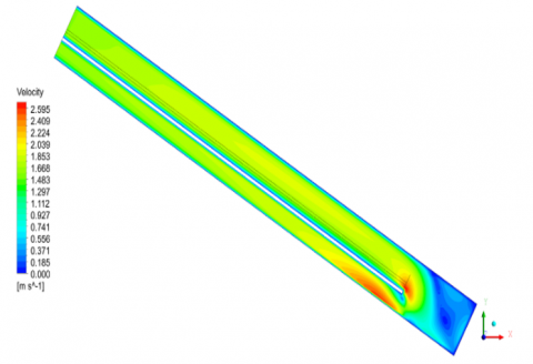
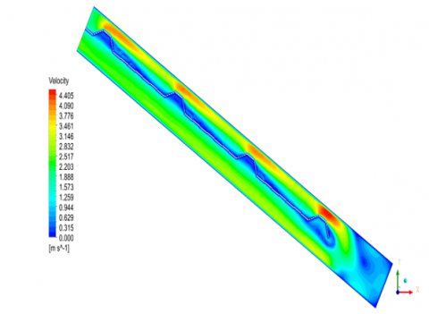
Finally, the maximum absorber temperature was focused on all regions of the U-corrugated plate with anti-parallel airflow at 12:00 noon due to the projection of the solar radiation in this region, in comparison to the flat plate absorber. Also, based on the pressure distribution, the trapezoidal plate saw an increase from 0.150 to 18.466 Pa at 0.0046 kg/s of airflow at 16:00. The maximum temperature also dropped, from 89.84 to 55.81℃, when the trapezoidal absorber plate was used at 16:00 with an airflow rate of 0.0046 kg/s. However, the maximum velocity for the trapezoidal absorber plate was determined to be 4.366 m/s as opposed to the flat plate’s maximum velocity of 0.463 m/s at an airflow rate of 0.0046 kg/s and at 16:00 as a consequence of the airflow’s momentum being increased by use of the trapezoidal absorber. The maximum absorber temperature was focused on all regions of the trapezoidal plate at 12:00 noon due to the projection of the solar radiation in this region compared to the flat plate absorber model. The discrepancies between the experimental and numerical results are due to sources of error and uncertainty in the measurements and instruments that were used in the study.
Figure 18. Velocity contours in the flat plate dual-flow SAH at noon at 0.0046 kg/s
Figure 19. Pressure contours in the U-corrugated plate utilized in an anti- parallel direction to airflow dual-flow SAH at noon at 0.0046 kg/s
Figure 20. Temperatures contours in the U-corrugated plate utilized in an anti- parallel direction to airflow dual-flow SAH at noon at 0.0046 kg/s
Figure 21. Velocity contours in the U-corrugated plate utilized in an anti- parallel direction to airflow dual-flow SAH at.0046 kg/s
4.3 Validation
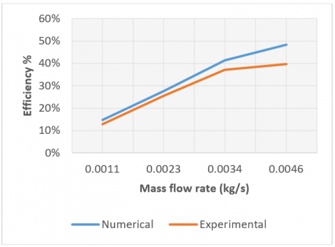
The input variables for the numerical model were air velocity, ambient temperature, inlet air temperature (Ti), and sun irradiation (I). The output air temperature (TO), pressure, air velocity, and absorber plate temperature (Tap) were all estimated using the simulation. The model’s unsteady-state simulation used averaged observed data from over the course of a day (09:00, 12:00, and 16:00). By contrasting the numerical findings with the outcomes of the experiments, the model was found to be valid, and also by comparing the results of the thermal efficiency in the experimental and numerical works for 0.0011 to 0.0046 kg/s, as shown in Figure 22. The relative error between the theoretical (Xtheo) and experimental (Xex) results is represented as:
Error $\%=\frac{x_{\text {theo }}-x_{\mathrm{ex}}}{x_{\text {theo }}} \times 100 \%$ (37)
With an average variance of 5.7%, the thermal efficiency of the flat plate dual-flow SAH for four mass flow rates, and the experimental and numerical findings were largely consistent. At the same mass flow rates, the numerical thermal efficiency values were greater than the experimental values. Because perfect circumstances were assumed for the numerical calculations, there was a greater heat transfer between the absorber plate and the moving air than would otherwise have been expected. The experimental results are lower than the calculated thermal performance values as a result. The outcomes of the current study were also contrasted with those from earlier publications. Hameed et al. [15] compared the thermal efficiency of our dual-flow SAH at a mass flow rate of 0.0023 kg/s to earlier research. Figure 23 shows that there is a strong consistency with this earlier research.
Figure 22. Experimental and numerical efficiency for flat plate SAH at four mass flow rates
Figure 23. Validation of the thermal efficiency of dual-flow SAH
Our experimental investigation was tested under outdoor weather conditions in Baghdad city (33.31ºN, 44.36ºE) on different days in April and May of 2022. The experimental and numerical works employed an experimental rig of a DPSAH with a specified design and dimensions to study the effect of varying airflow rates (0.0011-0.0046 kg/s) on thermal efficiency, absorber plate temperature, and outlet air temperature. We found that corrugation on the absorber plate increases the heat transfer rate and the thermal efficiency, especially when using a U-corrugated plate with anti-parallel airflow model. The thermal efficiencies obtained were 42.80%, 51.33%, 54.38%, and 55.53% and the energy gained was 156, 163, 193, and 187 W for the flat plate, U-corrugated plate with parallel airflow, U-corrugated plate with anti-parallel airflow, and trapezoidal corrugated plate with anti-parallel airflow, respectively. The best absorbent plate was the U-corrugated plate with anti-parallel airflow, followed by the trapezoidal plate with anti-parallel airflow, and lastly the U-corrugated plate with parallel airflow. The maximum absorber temperature was focused on all regions of the U-corrugated plate with anti-parallel airflow at 12:00 noon.
|
Abbreviations |
|
|
Dual-flow |
Dual-flow Solar Air Heater |
|
SAH |
Solar Air Heater |
|
DPSAH |
Double Pass Solar Air Heater |
|
SPSAH |
Single Pass Solar Air Heater |
|
SAH |
Solar Air Heater |
|
SFSAH |
Spiral Flow Solar Air Heater |
|
CFD |
Computational fluid dynamic |
|
PCM |
Phase change materials |
|
Symbols |
|
|
Ac |
Heater absorber area (m2) |
|
Aduct |
Cross- sectional area of the round duct (m2) |
|
Cp |
Specific heat (J/kg K) |
|
dduct |
Duct diameter (m) |
|
Dh |
Hydraulic diameter (m) |
|
h |
Convective heat transfer coefficient (W/m2 K) |
|
ha |
heat transfer coefficient between the glass and the ambient air (W/m2 K) |
|
hr |
Radiation heat transfer coefficient (W/m2 K) |
|
I |
Solar radiation intensity (W/m2) |
|
k |
Thermal conductivity of air (W/m K) |
|
m |
Mass flow rate of air (kg/s) |
|
Qu |
Energy gained (W) |
|
Re |
Reynolds number |
|
Ta |
Ambient air temperature (°C) |
|
Tap |
Absorber plate surface temperature (°C) |
|
Tbase |
Bottom plate temperature (°C) |
|
Tc |
Cover temperature (°C) |
|
Tf |
Fluid temperature (°C) |
|
Ti |
Inlet air temperature (°C) |
|
To |
Outlet air temperature (°C) |
|
ΔT |
Temperature difference of airflow (°C) |
|
U |
Overall heat loss coefficient (W/m2 K) |
|
Ub |
Back loss coefficient (W/m2 K) |
|
Ue |
Edge loss coefficient (W/m2 K) |
|
Ut |
Top loss coefficient (W/m2 K) |
|
Va |
Air velocity (m/s) |
|
Su |
Source momentum in x-direction |
|
Sv |
Source momentum in y-direction |
|
Sw |
Source momentum in z-direction |
|
Greek symbols |
|
|
εp |
Emittance of absorber plate |
|
εc |
Emittance of glass cover |
|
σ |
Stephen-Boltzman constant |
|
α |
Solar absorptance of heater plate |
|
$\rho_{\mathrm{a}}$ |
Air density (kg/m3) |
|
$\tau$ |
Solar transmittance of glazing |
|
η |
Thermal efficiency |
|
μ |
Air viscosity (m2 s) |
This appendix includes the simulation results of the pressure, temperature, and velocity contours for flat plate, U corrugated plate, and trapezoidal corrugated plate solar air collectors at different air mass flow rates.
A.1 Flat plate solar air collector
(a) Mass flow rate = 0.0011 kg/s
(b) Mass flow rate = 0.0023 kg/s
(c) Mass flow rate 0.0034 kg/s
(d) Mass flow rate = 0.0046 kg/s
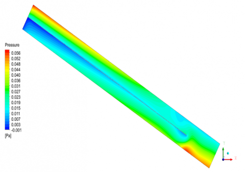
Figure A1. Pressure contours in the flat plate dual-flow SAH at noon and four air mass flow rates
(a) Mass flow rate = 0.0011 kg/s
(b) Mass flow rate = 0.0023 kg/s
(c) Mass flow rate 0.0034 kg/s
(d) Mass flow rate = 0.0046 kg/s
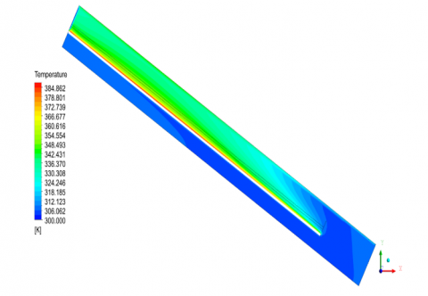
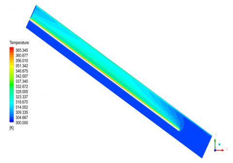
Figure A2. Temperature contours in the flat plate dual-flow SAH at noon and four air mass flow rates
(a) Mass flow rate = 0.0011 kg/s
(b) Mass flow rate = 0.0023 kg/s
(c) Mass flow rate 0.0034 kg/s
(d) Mass flow rate = 0.0046 kg/s
Figure A3. Velocity contours in the flat plate dual-flow SAH at noon and four air mass flow rates
B.1 U corrugated plate solar air collector
(a) Mass flow rate = 0.0011 kg/s
(b) Mass flow rate = 0.0023 kg/s
(c) Mass flow rate 0.0034 kg/s
(d) Mass flow rate = 0.0046 kg/s
Figure B1. Pressure contours in the U corrugated plate utilized in a parallel direction to airflow dual-flow SAH at noon and four air mass flow rates
(a) Mass flow rate = 0.0011 kg/s
(b) Mass flow rate = 0.0023 kg/s
(c) Mass flow rate 0.0034 kg/s
(d) Mass flow rate = 0.0046 kg/s
Figure B2. Temperature contours in the U corrugated plate utilized in a parallel direction to airflow dual-flow SAH at noon and four air mass flow rates
(a) Mass flow rate = 0.0011 kg/s
(b) Mass flow rate = 0.0023 kg/s
(c) Mass flow rate 0.0034 kg/s
(d) Mass flow rate = 0.0046 kg/s
Figure B3. Velocity contours in the U corrugated plate utilized in a parallel direction to airflow dual-flow SAH at noon and four air mass flow rates
(a) Mass flow rate = 0.0011 kg/s
(b) Mass flow rate = 0.0023 kg/s
(c) Mass flow rate 0.0034 kg/s
(d) Mass flow rate = 0.0046 kg/s
Figure B4. Pressure contours in the U corrugated plate utilized in anti-parallel direction to airflow dual-flow SAH at noon and four air mass flow rates
(a) Mass flow rate = 0.0011 kg/s
(b) Mass flow rate = 0.0023 kg/s
(c) Mass flow rate 0.0034 kg/s
(d) Mass flow rate = 0.0046 kg/s
Figure B5. Temperatures contours in the U corrugated plate utilized in anti-parallel direction to airflow dual-flow SAH at noon and four air mass flow rates
(a) Mass flow rate = 0.0011 kg/s
(b) Mass flow rate = 0.0023 kg/s
(c) Mass flow rate 0.0034 kg/s
(d) Mass flow rate = 0.0046 kg/s
Figure B6. Velocity contours in the U corrugated plate utilized in anti-parallel direction to airflow dual-flow SAH at noon and four air mass flow rates
C.1 Trapezoidal corrugated solar air collector
(a) Mass flow rate = 0.0011 kg/s
(b) Mass flow rate = 0.0023 kg/s
(c) Mass flow rate 0.0034 kg/s
(d) Mass flow rate = 0.0046 kg/s
Figure C1. Pressure contours in the trapezoidal corrugated plate utilized in anti-parallel direction to airflow dual-flow SAH at noon and four air mass flow rates
(a) Mass flow rate = 0.0011 kg/s
(b) Mass flow rate = 0.0023 kg/s
(c) Mass flow rate 0.0034 kg/s
(d) Mass flow rate = 0.0046 kg/s
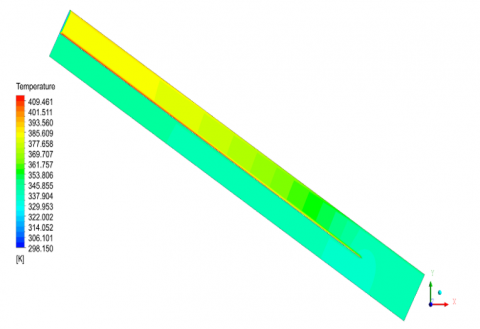
Figure C2. Temperatures contours in the trapezoidal corrugated plate utilized in anti-parallel direction to airflow dual-flow SAH at noon and four air mass flow rates
(a) Mass flow rate = 0.0011 kg/s
(b) Mass flow rate = 0.0023 kg/s
(c) Mass flow rate 0.0034 kg/s
(d) Mass flow rate = 0.0046 kg/s
Figure C3. Velocity contours in the trapezoidal corrugated plate utilized in anti-parallel direction to airflow dual-flow SAH at noon and four air mass flow rates
[1] Incropera, F.P., DeWitt, D.P., Bergman, T.L., Lavine, A.S. (2011). Fundamentals of Heat and Mass Transfer. Seventh Edition. John Wiley and Sons Inc., New York, USA.
[2] Metwally, M.N., Abou-Ziyan, H.Z., El-Leathy, A.M. (1997). Performance of advanced corrugated-duct solar air collector compared with five conventional designs. Renewable Energy, 10(4): 519-537. https://doi.org/10.1016/s0960-1481(96)00043-2
[3] Liu, T., Lin, W., Gao, W., Luo, C., Li, M., Zheng, Q., Xia, C. (2007). A parametric study on the thermal performance of a solar air collector with a v-groove absorber. International Journal of Green Energy, 4(6): 601-622. https://doi.org/10.1080/15435070701665370
[4] Gao, W., Lin, W., Liu, T., Xia, C. (2007). Analytical and experimental studies on the thermal performance of cross-corrugated and flat-plate solar air heaters. Applied Energy, 84(4): 425-441. https://doi.org/10.1016/j.apenergy.2006.02.005
[5] Karim, M.A., Hawlader, M. (2004). Development of solar air collectors for drying applications. Energy Conversion and Management, 45(3): 329-344. https://doi.org/10.1016/S0196-8904(03)00158-4
[6] Choudhury, C., Garg, H.P. (1991). Design analysis of corrugated and flat plate solar air heaters. Renewable Energy, 1(5-6): 595-607. https://doi.org/10.1016/0960-1481(91)90003-8
[7] Gao, W., Lin, W., Lu, E. (2000). Numerical study on natural convection inside the channel between the flat-plate cover and sine-wave absorber of a cross-corrugated solar air heater. Energy Conversion and Management, 41(2): 145-151. https://doi.org/10.1016/S0196-8904(99)00098-9
[8] Forson, F.K., Nazha, M.A., Rajakaruna, H. (2003). Experimental and simulation studies on a single pass, double duct solar air heater. Energy Conversion and Management, 44(8): 1209-1227. https://doi.org/10.1016/S0196-8904(02)00139-5
[9] Yeh, H.M., Ho, C.D., Hou, J.Z. (2002). Collector efficiency of double-flow solar air heaters with fins attached. Energy, 27(8): 715-727. https://doi.org/10.1016/S0360-5442(02)00010-5
[10] Karim, M.A., Hawlader, M.N.A. (2006). Performance investigation of flat plate, v-corrugated and finned air collectors. Energy, 31(4): 452-470. https://doi.org/10.1016/j.energy.2005.03.007
[11] Fudholi, A., Sopian, K., Othman, M.Y., Ruslan, M.H., Bakhtyar, B. (2013). Energy analysis and improvement potential of finned double-pass solar collector. Energy Conversion and Management, 75: 234-240. https://doi.org/10.1016/j.enconman.2013.06.021
[12] Ho, C.D., Yeh, H.M., Cheng, T.W., Chen, T.C., Wang, R.C. (2009). The influences of recycle on performance of baffled double-pass flat-plate solar air heaters with internal fins attached. Applied Energy, 86(9): 1470-1478. https://doi.org/10.1016/j.apenergy.2008.12.013
[13] El-Sebaii, A.A., Aboul-Enein, S., Ramadan, M.R.I., Shalaby, S.M., Moharram, B.M. (2011). Investigation of thermal performance of-double pass-flat and v-corrugated plate solar air heaters. Energy, 36(2): 1076-1086. https://doi.org/10.1016/j.energy.2010.11.042
[14] Liu, T., Lin, W., Gao, W., Xia, C. (2007). A comparative study of the thermal performances of cross-corrugated and v-groove solar air collectors. International Journal of Green Energy, 4(4): 427-451. https://doi.org/10.1080/15435070701465847
[15] Hameed, H., Diabil, H., Saeed, M. (2021). Performance of a new model of air heating system: Experimental investigation. Journal of Mechanical Engineering Research and Developments, 44(5): 420-432.
[16] Abuşka, M., Şevik, S. (2017). Energy, exergy, economic and environmental (4E) analyses of flat-plate and V-groove solar air collectors based on aluminium and copper. Solar Energy, 158: 259-277. https://doi.org/10.1016/j.solener.2017.09.045
[17] Ho, C.D., Chang, H., Hsiao, C.F., Huang, C.C. (2018). Device performance improvement of recycling double-pass cross-corrugated solar air collectors. Energies, 11(2): 338. https://doi.org/10.3390/en11020338
[18] Arunkumar, H.S., Kumar, S., Karanth, K.V. (2021). Experimental study on thermo-hydraulic performance of a solar air heater with rectangular perforated duct inserts. Solar Energy, 227: 179-189. https://doi.org/10.1016/j.solener.2021.09.005
[19] Ameri, M., Sardari, R., Farzan, H. (2021). Thermal performance of a V-Corrugated serpentine solar air heater with integrated PCM: A comparative experimental study. Renewable Energy, 171: 391-400. https://doi.org/10.1016/j.renene.2021.02.113
[20] Rajendran, V., Ramasubbu, H., Rajarathinam, J.V., Pichandi, R. (2022). Experimental study on the thermal performance of a solar air heater integrated with multi-geometry arrangements over the absorber plate. Environmental Science and Pollution Research, 29(25): 38331-38345. https://doi.org/10.1007/s11356-022-18830-x
[21] El-Said, E.M., Abou Al-Sood, M.M., Elsharkawy, E.A., Abdelaziz, G.B. (2022). Tubular solar air heater using finned semi-cylindrical absorber plate with swirl flow: Experimental investigation. Solar Energy, 236: 879-897. https://doi.org/10.1016/j.solener.2022.03.054
[22] Amara, W.B., Bouabidi, A. (2023). Experimental studies and 3D simulations for the investigation of thermal performances of a solar air heater with different spiral-shaped baffles heights. Journal of Building Engineering, 65: 105662. https://doi.org/10.1016/j.jobe.2022.105662
[23] Agrawal, Y., Yugbodh, K., Ayachit, B., Tenguria, N., Nigam, P.K., Gautam, A., Yadav, A.S., Sharma, A., Alam, T. (2023). Experimental investigation on thermal efficiency augmentation of solar air heater using copper wire for discrete roughened absorber plate. Materials Today: Proceedings. https://doi.org/10.1016/j.matpr.2022.12.244
[24] Farzan, H., Zaim, E.H. (2023). Thermal analysis of a new double-pass solar air heater using perforated absorber and porous materials: An experimental study. Thermal Science and Engineering Progress, 38: 101680. https://doi.org/10.1016/j.tsep.2023.101680
[25] Kumar, P.G., Sakthivadivel, D., Balaji, K., Salman, M., Kim, S.C. (2021). Performance enhancement of a double-pass solar air heater with a shot-blasted absorber plate and winglets. Journal of Mechanical Science and Technology, 35(6): 2743-2753. https://doi.org/10.1007/s12206-021-0544-x
[26] Yousef, B.A.A., Adam, N.M. (2008). Performance analysis for flat plate collector with and without porous media. Journal of Energy in Southern Africa, 19(4): 32-42. https://doi.org/10.17159/2413-3051/2008/v19i4a3336
[27] Abdullah, A.S., Abou Al-sood, M.M., Omara, Z.M., Bek, M.A., Kabeel, A.E. (2018). Performance evaluation of a new counter flow double pass solar air heater with turbulators. Solar Energy, 173: 398-406. https://doi.org/10.1016/j.solener.2018.07.073
[28] Rasham, A.M., Alaskari, M.M. (2017). Thermal analysis of double-pass solar air collector with different materials of absorber plate and different dimensions of air channels. International Journal of Science and Research (IJSR), 6(8): 901-908. https://doi.org/10.21275/6081701
[29] Acır, A., Emin Canlı, M., Ata, İ., Erdi Tanürün, H. (2019). Effects of a circular-shaped turbulator having varying hole numbers on energy and exergy efficiencies of a solar air heater. International Journal of Ambient Energy, 40(7): 739-748. https://doi.org/10.1080/01430750.2017.1423385
[30] Sreenivaslu, G., Rao, P.R., DT, A.K., Pattanaik, A. (2019). Experimental ınvestigation on performance of solar air heaters with thermal storage. International Journal of Renewable Energy and its Commercialization, 5(1): 37-46. https://doi.org/10.37628/jrec.v5i1.770
[31] Ovando Chacon, G.E., Ovando Chacon, S.L., Prince Avelino, J.C. (2010). Numerical modeling of fluid dynamics and heat transfer of glass flow in a short channel. Brazilian Journal of Chemical Engineering, 27: 663-675. https://doi.org/10.1590/s0104-66322010000400018
[32] Churchill, S.W., Chu, H.H. (1975). Correlating equations for laminar and turbulent free convection from a vertical plate. International Journal of Heat and Mass Transfer, 18(11): 1323-1329. https://doi.org/10.1016/0017-9310(75)90243-4
[33] Holman, J.P. (1986). Heat Transfer, 6th Edition. McGraw-Hill, New York. https://www.scribd.com/doc/133650331/HEAT-TRANSFER-BY-J-P-HOLMANN.