Rokkala Rudrabhiramu*![]() | K. Kiran Kumar
| K. Kiran Kumar![]() | Kutchibotla Mallikarjuna Rao
| Kutchibotla Mallikarjuna Rao![]()
© 2023 IIETA. This article is published by IIETA and is licensed under the CC BY 4.0 license (http://creativecommons.org/licenses/by/4.0/).
OPEN ACCESS
The strategic utilization of nanofluids within square enclosures comprising horizontal fins presents promising applications ranging from electronic cooling systems, nuclear reactor heat management, to solar energy collection. This study employs numerical simulations to delineate the intricacies of heat transfer phenomena under the influence of natural convection in a laminar flow regime within a square enclosure of varied cavity dimensions. The enclosure is filled with a nanofluid composed of Al2O3 at a concentration of 3%, suspended in H2O, Ethylene Glycol (EG), and H2O/EG mixtures. The position and length of a specific fin are scrutinized, along with an array of Rayleigh numbers. Numerical analyses are executed using the homogeneous heat transfer model in Ansys Fluent. Observations reveal a direct correlation between the increase in Rayleigh number (ranging from 103 to 106), the conductivity ratio and an elevation in the surface temperature, consequently contributing to an enhanced efficiency of heat transmission. Optimal fin placement for maximum heat transfer improvement is detected at a height of 0.5 m and a length of 0.75 m within the enclosure. The study further investigates the Nusselt number variations of Al2O3 nanoparticles at a 3% volume concentration when suspended in water, a combination of water and Ethylene Glycol, and Ethylene Glycol alone. Upon a rise in wall temperature, an increase in the Rayleigh number is noted, inducing heightened convective activity and hence, improved heat transmission. Additionally, it is established that an increase in the conductivity ratio of the fin significantly augments heat transfer enhancement.
CFD, square enclosure, extended surface, PCM, conductivity ratio Rayleigh number, fin location and optimisation
In the last decade, the scientific community has turned its attention to the enhancement of heat transfer within nanofluid enclosures and cavities, with particular focus on the use of fins and partitions [1, 2]. These investigations have significant implications for an array of fields, from the cooling of nuclear reactors to the optimization of solar collectors and electronic devices. For instance, the work by Khanafer et al. [3] offers experimental insights into the functioning of nanofluid systems. Their study, which compared experimental data with a numerical model derived from the lattice Boltzmann method, suggested a novel approach to representing nanofluids. Rather than treating the nanofluid as a singular, integrated system, they proposed a two-layer model, advocating for the inclusion of temperature-dependent thermophysical features in numerical modeling [3]. Contrarily, Li et al. [4] concentrated their efforts on the natural convection of Al2O3-based nanofluids. By conducting experimental research on nanoparticles of varying concentrations, they made the intriguing observation that the heat transmission decreases as the volume percentage of nanoparticles increases. This unexpected finding was ascribed to the increasing viscosity of the nanofluid and the onset of Brownian motion, a conclusion that contradicts previous findings.
Equally noteworthy are the studies that have explored the impact of cavity geometry and location within an enclosure on convection phenomena [5]. Hwang et al. [6] drew upon an Al2O3/Water nanofluid buoyancy study to examine heat transfer within a rectangular chamber. Their findings suggest that as nanoparticle size increases, the ratio of the base fluid's thermal conductivity to that of the nanofluids decreases. Putra et al. [7] contributed to the field by investigating the effects on a cylindrical device under adiabatic conditions, concluding that the concentration of nanoparticles and the aspect ratio of the cylinder led to a decrease in natural convective heat transfer. Furthermore, several studies have probed into the effects of inserting a fin or partition within an enclosure on the flow field and heat transmission [8, 9]. Considerable evidence from prior research indicates that the introduction of a fin or partition within an enclosure significantly influences both the flow field and heat transfer [10-15]. The effects of natural convection within a square enclosure, featuring an incline and a fin affixed to the cold vertical side, were quantitatively assessed by Frederick [10]. Bilgen [11] undertook computational examination of buoyancy-driven convection within a nonlinear heated chamber integrated with a horizontal fin. This study revealed that fin placement critically impacts the rate of heat transfer within a cavity, with the minimal enhancement of heat occurring when the fin was located in the cavity's center. Building on this, Shi and Khodadadi [12] discovered an increase in heat flux during the assessment of laminar natural convection within a partially heated square cavity. This was observed regardless of the fin's geometry when a thin fin was connected to the hot wall. Further exploration by Frederick and Valencia [13] coupled a highly conductive horizontal fin surface to a heated wall in the center of a square enclosure. They reported enhanced heat transfer upon increasing the thermal resistance ratio. In a separate investigation, Nag et al. [14] conducted a numerical study of natural convection involving adiabatic and highly conductive horizontal fins. It was found that compared to an enclosure without a fin, the Nusselt number on the cold wall increased when a highly resistant fin was used. However, when an adiabatic fin was employed, the Nusselt number was lower than in the case without a fin. Tasnim and Collins [15] performed a numerical analysis of free convection in an air-filled square cavity, incorporating a highly resistant fin affixed to the heated wall. They explored natural convection statistically with the fin attached to the hot wall, a heating left vertical side, a cooling right vertical side, and top and bottom adiabatic sides [16-18]. Additionally, Nimmagadda et al. [19] conducted an investigation on microchannels with a liquid/solid interface using different combinations of nanofluids. Their findings suggested that an increase in Reynolds number enhances the average heat transfer coefficient, subsequently lowering the temperature at the solid-liquid interface. They reported that a hybrid nanofluid, comprised of water, Al2O3, and Ag nanoparticles, augments heat transfer more significantly than a basic nanofluid consisting solely of Al2O3 and Ag particles. Lv et al. [20] experimentally examined the potential of composite phase change materials (CPCMs) in commercially available Lithium-Ion battery modules. In their synthetic PCMs, expanded graphite/graphene components were added to paraffin. Their study, which spanned 200 cycles, suggested that incorporating PCMs into the computational model reduces the temperature to below 60℃ and extends battery life by 73.2% compared to bare modules without PCMs. However, the optimization of CPCM's structural and physical characteristics was not investigated in this study.
In a pursuit to optimize the efficiency of photovoltaic (PV) panels, Abdulmunem and Samin [21] performed an experimental examination of the role of various phase change materials (PCMs). Their findings indicated a 5.93% decrease in PV cell temperature when using PCM, and a further enhancement of 13.29% when 0.2% MWCNT was added. Notably, they reported that the performance gain offered by MWCNT over PCM/CFM was only marginal. A subsequent experimental study [22] explored the use of PCM in solar water systems, aiming to enhance heat transfer and decrease the friction factor. The inclusion of 6kg PCM resulted in an overall performance increase of more than 30%. Interestingly, the study revealed an initial drop in efficiency upon the integration of PCM into the solar system, which was compensated for by a subsequent significant improvement. This behavior was attributed to the PCM's initial reluctance to absorb heat [23]. The study also addressed the evolution of inorganic PCMs and strategies to overcome their limitations. Further research by Park et al. [24] involved both experimental and computational analysis of a square container with varying axis ratios. The investigation encompassed axis ratios (AR) of 0.11, 0.20, 0.67, and 1. It was determined that the melting rate varied directly with AR up to a ratio of 0.2, beyond which it increased exponentially. The adoption of a 0.05 AR elliptical container was found to enhance heat transfer by a factor of 2.7. In another experimental study, Longeon et al. [25] investigated a counter-flow heat exchanger with latent heat storage, subsequently validating the results numerically. The investigation focused on how the injection side of the heat transfer fluid (HTF) affected charging and discharging. It was concluded that injecting HTF from the top side resulted in superior charging outcomes compared to bottom-side injection.
Dukhan et al. [26] undertook an experimental analysis of a horizontally positioned, concentric twin-pipe heat exchanger, with Rubitherm RT-42 filling the annular gap. The HTF used was water heated to temperatures between 60 and 80℃ and injected into the inner tube. Camera images were used to record the melt fraction of the PCM. The investigators concluded that the initial phase of heat transfer was dominated by conduction, with the contribution of natural convection increasing over time. As the HTF temperature increased, the heat transfer rate also increased, with a rise of 46% being observed.
Avci et al. [27] conducted an experimental investigation of a counter-flow heat exchanger, employing paraffin as the phase change material (PCM) for latent heat storage. The study was subsequently validated through numerical comparison. Their findings indicated that the temperature field's inconsistent behavior led to a decrease in the PCM's melting behavior with increasing depth. Further research by Liu et al. [28] involved the preparation and testing of PCM-encapsulated monomer within a straightforward quaternary ammonium. An encapsulation efficiency of 84.50% was reported, with no evidence of PCM leakage. The simultaneous heat transfer within a hollow drive, induced by a stepped lid containing nanofluid, was numerically examined in another study [29]. Aluminum oxide nanomaterials were utilized, with water serving as the base fluid. Unlike the rotating lid, which induced forced convection, the stepped blocks were perceived as high-temperature silicon carbide. The study was conducted for forced and mixed convection, with Grashoff numbers of 5000, 3000, and 20000, and Reynolds numbers ranging from 100 to 500. The results suggested that there was no change in convection heat transfer for high Reynolds numbers. Nguyen et al. [30] modeled and analyzed a thermal management system to understand the behavior of hydrogen produced by a solar electrolyzer. The investigation, conducted using HOMER and MATLAB software, revealed that employing PCM could conserve up to 12% of the hydrogen produced by the electrolyzer. Furthermore, they recommended increasing the effective thermal conductivity of the PCM to at least 1.5 W/m.K to enhance the system's durability. In a different approach, Sheng et al. [31] developed and described a polyethylene glycol-based pamelo peel foam composite PCM for use in solar systems. To improve their light-absorbing capacity, MXene nanosheets were incorporated into these composite materials.
However, as previous studies [12, 15] have highlighted, no definitive conclusions have been reached using the various thermal conductivity models and procedures presented in the literature. According to Saghir et al. [2], the thermal conductivity model should take into account Brownian motion in micro-convection processes. The current study uses numerical simulations employing a nano-fluid mixture to explore heat transfer processes under natural convection in a laminar flow regime within a square enclosure with various cavities. For a given fin length and position, and varying Rayleigh numbers, H2O, EG, and H2O/EG mixes with a 3% Al2O3 concentration were considered. The numerical analysis, conducted using Ansys Fluent's homogeneous heat transfer model, demonstrated an increase in surface temperature and heat transfer rate as the Rayleigh number and conductivity ratio increased.
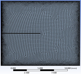
Finite volume analysis (FVM) of the effect of temperature distribution (or heat removal) on a 2-D square enclosure (dimensions W×W) containing base fluid with nanoparticles is studied. The lateral panels have a constant temperature, while the top and bottom walls of the hollow are insulated. A straight fin of dimensions l×b is attached with varying heights h from the adjacent base edge. Three distinct base fluids are examined by the nanofluid: water, ethylene glycol (EG), and a mixture of water and EG. The nanoparticle selected for study is Al2O3, and the percent volume content of these nanoparticles in the nanofluid is maintained at 3%. Figure 1 shows the boundary conditions used for the square enclosure and negative gravitational force inside the cavity. It is assumed that the mixture of the baseline fluid and the nanoparticles is homogenous and functions as a one-phase system. The buoyancy effect brought on by lateral wall heating is taken into account by the gravity vector. Figure 2 illustrates how quadrilaterals were mostly used in the mesh grid for the investigation.
Figure 1. Schematic computational model with input parameters
Figure 2. Meshed computational model
Assuming that the nanofluid is homogenized with the nanoparticles, the nanoparticles are readily fluidized inside the base fluid. It is thought of as a single system, the nanofluid. This study's primary goal is to understand the flow dynamics of nanofluids resulting from the increased heat transfer rate (or heat enhancement) brought on by including a plane fin. Consequently, any effects brought on by outside forces (such as a magnetic field) are discounted.
u = v = 0, T = Th, at x = 0, & 0 ≤ y ≤ W
u = v = 0, T = Tc, at x = W, & 0 ≤ y ≤ W
u = v = 0, $\frac{\partial T}{\partial y}=0$, at y = 0, W & 0 ≤ x ≤ W
Mass density, ($\rho_{\text {nano fluid }}$ ):
$\rho_{\text {nano fluid }}=\varphi \rho_{n p}+(1-\varphi) \rho_{\text {base fluid }}$ (1)
Absolute viscosity, ($\mu_{\text {nano fluid }}$ ):
$\mu_{\text {nano fluid }}=\frac{\mu_{\text {base fluid }}}{(1-\varphi)^{2.5}}$ (2)
Thermal conductivity, ($k_{\text {nano fluid }}$ ):
$\frac{k_{\text {nano fluid }}}{k_{\text {base fluid }}}=\frac{k_{n p}\,+2 k_{\text {base fluid }}\,\,\,\,+2\left(k_{n p}-k_{\text {base } f l u i d}\,\,\,\,\,\,\,\,\,\,\right) \varphi}{k_{n p}\,+2 k_{\text {base fluid }}\,\,\,\,-2\left(k_{n p}-k_{\text {base fluid }}\,\,\,\,\,\,\,\,\,\,\right) \varphi}$ (3)
Thermal volume expansion, ($\beta_{n f}$ ):
$(\rho \beta)_{\text {nano fluid }}=\varphi \rho_{n p} \beta_{n p}+(1-\varphi) \rho_{\text {base fluid }} \beta_{\text {base fluid }}$ (4)
Specific heat capacity, ($C_{p_{\text {nano fluid }}}$ ):
$\begin{gathered}\left(\rho c_p\right)_{\text {nano fluid }}=\varphi \rho_{n p} c_{p_{\text {np }}}+(1- \varphi) \rho_{\text {base fluid }}\,\, c_{p_{\text {base fluid }}}\end{gathered}$ (5)
The current study examines and compares three base fluids with maintaining 3% Al2O3 nanoparticle concentrations throughout. The different combinations studied are 0.2/0.8, 0.4/0.6, 0.6/0.4, and 0.8/0.2 water/EG mixtures. Table 1 represents the properties of the above-all combinations.
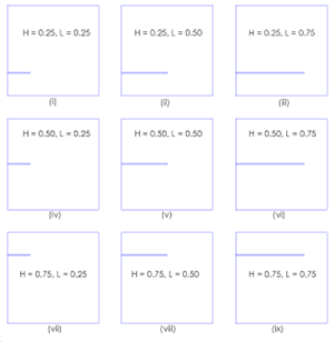
Temperatures of 310 K and 290 K, respectively, are always maintained on the high and low-temperature sides. Fin lengths are changed and evaluated for Lf=25, 50, and 75% of W with a consistent fin thickness of Bf=0.01. Additionally, fins are analysed at three distinct places, Hf=25, 50, and 75% of W. It clearly shows that there is a possibility of nine combinations with the fin geometrical and positional parameters. Figure 3 shows all the combinations.
The heat transfer among the fins and nanofluid also depends on the fin's conductivity. Conductivity ratio (Rk) is a novel word that refers to the thermal conductivity of the fin material to the thermal conductivity of the nanofluid. At four distinct Rk values, the effect of Rk variation on the overall heat transfer rate is investigated. The square cavity filled with nanofluid is studied for Rayleigh numbers Ra=103, 104, 105, and 106. As a result, four factors are examined (one by one): (1) length and location of the fin, (2) composition of the base fluid, (3) conductivity ratio Rk and (4) Rayleigh number. The mass density in the numerical analysis is considered to follow the Boussinesq approximation to reduce the computational time pertaining to solving the non-linearity of the Navier-Stokes equation. The dominating continuity, momentum, and energy equations for the incompressible flow are as follows.
$\frac{\partial u}{\partial x}+\frac{\partial v}{\partial y}=0$ (6)
$\begin{gathered}u \frac{\partial u}{\partial x}+v \frac{\partial u}{\partial y}= \frac{1}{\rho_{n f}}\left[-\frac{\partial P}{\partial x}+\mu_{n f}\left(\frac{\partial^2 u}{\partial x^2}+\frac{\partial^2 u}{\partial y^2}\right)\right] + \left\{(g \sin \theta)(\rho \beta)_{n f}\left(T-T_c\right)\right\}\end{gathered}$ (7)
$\begin{gathered}u \frac{\partial v}{\partial x}+v \frac{\partial v}{\partial y}= \frac{1}{\rho_{n f}}\left[-\frac{\partial P}{\partial y}+\mu_{n f}\left(\frac{\partial^2 v}{\partial x^2}+\frac{\partial^2 v}{\partial y^2}\right)\right]+ \left\{(g \cos \theta)(\rho \beta)_{n f}\left(T-T_c\right)\right\}\end{gathered}$ (8)
$u \frac{\partial T}{\partial x}+v \frac{\partial T}{\partial y}=\alpha_{n f}\left(\frac{\partial^2 T}{\partial x^2}+\frac{\partial^2 T}{\partial y^2}\right)$ (9)
3.1 Solution procedure
A CFD analysis of the free convection problem in the square cavity is carried out using the Fluent 18.1 software. With the default relaxation factor values, the SIMPLE technique is used. All of the governing equations' residuals are set to 10.4. Table 2 displays the mesh sensitivity research for the Al2O3-water nanofluid with =3% and T=Th–Tc=12 K. This mesh grid its plot for the grid independence test is shown in Figure 4 and Figure 5, respectively.
A square enclosure of 8 cm in length filled with Al2O3-water nanofluid, as described in the open literature [17, 18], is used to validate the current study. The horizontal walls of the hollow are not isothermal, but the vertical walls are. Table 3 summarises the findings. Even though the rise in variance from 2.31 to 4.34% with the increase in nanoparticle concentration is recorded, the difference is less and well within the acceptable range. Hence the methodology adopted in the present numerical study is acceptable.
|
Case No. |
Parameters |
|
1 |
Lf = 0.25W, Hf = 0.25W, Bf = 0.01 |
|
2 |
Lf = 0.50W, Hf = 0.25W, Bf = 0.01 |
|
3 |
Lf = 0.75W, Hf = 0.25W, Bf = 0.01 |
|
4 |
Lf = 0.25W, Hf = 0.50W, Bf = 0.01 |
|
5 |
Lf = 0.50W, Hf = 0.50W, Bf = 0.01 |
|
6 |
Lf = 0.75W, Hf = 0.50W, Bf = 0.01 |
|
7 |
Lf = 0.25W, Hf = 0.75W, Bf = 0.01 |
|
8 |
Lf = 0.50W, Hf = 0.75W, Bf = 0.01 |
|
9 |
Lf = 0.75W, Hf = 0.75W, Bf = 0.01 |
Figure 3. Different combinations with length and position of the fin
Table 1. Properties of water/EG combinations and Al2O3
|
Property |
H2O |
0.8/0.2 W/EG |
0.6/0.4 W/EG |
0.4/0.6 W/EG |
0.2/0.8 W/EG |
Pure EG |
Al2O3 |
|
ρf (kg.m-3) |
999.09 |
1029.986 |
1049.715 |
1086.038 |
1109.615 |
1134.264 |
3977.94 |
|
cpf (J/kg.K) |
4191.36 |
3836.398 |
3494.471 |
3114.441 |
2697.311 |
2355.384 |
767.079 |
|
kf(W/m.K) |
0.609 |
0.49475 |
0.405338 |
0.333808 |
0.281153 |
0.256316 |
39.73899 |
|
µf (mPa/s) |
0.901 |
1.476386 |
2.598844 |
4.57073 |
8.383042 |
15.26947 |
- |
|
α x107 (m2/s) |
1.5 |
1.291837 |
1.128571 |
1.018367 |
0.969388 |
0.989796 |
134.3878 |
|
β (1/K) |
0.00021 |
0.000281 |
0.000351 |
0.000421 |
0.000491 |
0.000571 |
2.4E-05 |
|
Pr |
6.08214 |
11.23242 |
21.9939 |
41.86356 |
78.94758 |
137.755 |
- |
Figure 4. Mesh grid for sensitivity analysis
Figure 5. Variation of Nu with number of grid elements
Table 2. Grid sensitivity ananlysis
|
No. of Elements |
Total Elements |
Heat flux (W/m2) |
Nu |
|
41x41 |
1600 |
3876.92 |
39.08 |
|
81x81 |
6400 |
3072.95 |
30.97 |
|
121x121 |
14400 |
2812.9 |
28.35 |
|
161x161 |
25600 |
2812.6 |
28.35 |
|
321x321 |
102400 |
2737.5 |
27.59 |
Table 3. Validation of the results
|
Nanoparticle Vol % |
Nu (from Ho et al. [17]) |
Nu (from Sahgir et al. [18]) |
Nu (from Present Analysis) |
|
1 |
32.8 |
32.46 |
33.62 |
|
2 |
33.41 |
32.49 |
33.23 |
|
3 |
29.99 |
31.96 |
30.62 |
Figure 6. Comparison of no fin temperature contour with fin a in square cavity
3.2 Numerical results & discussion
It is necessary to study the effect of fin on the heat transmission behavior in a square container with no fin and with the incorporation of the fin. The temperature contours in Figures 6(a) and 6(b) are for a computational model without a fin and a square cavity with a fin, accordingly, filled with Al2O3/H2O nanofluid at a concentration of 3%, Ra=106 is the Rayleigh number with this system. The model with extended surface is situated at Hf=0.5 and has a fin length of Lf=0.5. The fin has a breadth of Bf=0.01. The fin's conductivity ratio is Rk=1000. It stands to reason that the inclusion of a fin allows heat from the heated wall to spread further into the hollow. Compared to a no-fin cavity scenario, this alters the heat transfer behavior and improves heat transmission. The comparison of temperature contour between no fin and finned container shows the increase in temperature distribution in later case is more than earlier. Using stream function contours, it is possible to comprehend better how increased total heat output is caused by increasing heat penetration. The stream function curves for no-fin and with-fin are thus shown in Figures 7 and 8, respectively.
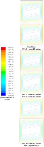
Figure 7. Comparison of stream function contour with no fin for different water/EG mixtures at Ra=106
The streamlined contours of the square container without a fin are shown in Figure 7 for various water/EG base fluid mixtures. The core area grows, and the streamline travels toward the isothermal wall as the fraction of EG in the H2O/EG increases. As the fraction of EG increases, this streamlined movement towards the isothermal walls causes an increase in heat. As a result, the Nusselt number rises from 9.08 to 9.12 when the base fluid is changed from pure water to 100% EG.
Figure 8 depicts the stream function for a computer model with a fin and various stream morphologies. Vortices may be visible on both sides of the fin due to its insertion. These vortices are absent from the no-fin cavity configuration (Figure 7).
Figure 8. Comparison of stream function contours with fin of Hf and Lf =0.5W for different water/EG mixtures at Ra=106
The vortices created by the fin exacerbate turbulence. Due to this improved heat flux, fin systems may increase heat transfer by up to 8.3 percent compared to no-fin systems, as shown in Table 4. The streamline plot variation for various combinations of water and EG base fluid is also shown in Figure 8. In Figure 7, it can be observed that the streamlines move closer to the isothermal wall as the percentage of EG in the water-EG mixture increases.
Table 4. Comparison of Nu for No Fin vs Finned square container
|
% EG in Mixture |
Nu (Without Fin) |
Nu with Fin |
% Enhancement in Nu |
|
0 |
8.99 |
9.99 |
7.89 |
|
20 |
8.86 |
9.42 |
7.64 |
|
40 |
9.23 |
10.12 |
7.11 |
|
60 |
9.06 |
9.48 |
7.43 |
|
80 |
9.23 |
9.65 |
7.96 |
3.3 Influence of Al2O3 nanoparticles with fins
The following crucial topic is the impact of fin length and placement on heat enhancement. The present research considers nine different fin designs, as shown in Figure 3. The inquiry continues by looking at how fin length and placement affect the phenomenon of heat transport. This study is carried out on two different Rayleigh numbers (103 and 106). A comparison of the contours of temperature and stream function for different combinations is presented. Figures 9 and 10 depict the temperature & stream function contours for Ra=103, respectively, whereas Figures 11 and 12 depict the temperature with stream function contours for Rayleigh number 106.
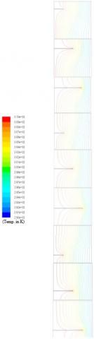
Figure 9. Comparison of Temperature contours with 30% aluminium oxide nano particles in water for different Hf & Lf at Ra=1000 and Rk=1000
The impact of fin height and length on temperature distribution is seen in Figure 9. It indicates that heat penetration increases as fin length increases for a fixed fin height. The above graphic makes it challenging to comprehend the impact of the fin position, however. With the aid of the stream function shown in Figure 10, the effect of fin position on heat augmentation is demonstrated.
Figure 10. Comparison of Stream function contours with 30% aluminium oxide nano particles in water for different Hf & Lf at Ra=1000 and Rk=1000
Figure 11. Comparison of Temperature contours with 30% aluminium oxide nano particles in water for various Hf & Lf at Rk=1000 and Ra=106
As shown in Figure 10, for H=0.25 and 0.75 at Ra=103, the fin blocks the vortex below and above the fin surface. The vortex structure appeared on the top and bottom sides of the fin located at Hf and Lf of 0.5, and this will be selected as the optimal location for a given Rayleigh number. Figure 11 shows the temperature contours of 0.3/0.7 Al2O3 nanofluid at 106 Rayleigh number. Comparing Figures 9 and 11, the effect of Rayleigh number on the heat transfer can be found that isotherms for 106 is closely packed than 103 Rayleigh number.
When comparing Figures 10 and 12, Rayleigh number 106 exhibits more vorticity. This stream function covers both the bottom and top part of the fin surface due to the improvement in vorticity structure, and this process will continue for all the various fin heights. This means that when the Rayleigh number climbed, heat enhancement did too. This research shows that at positions Hf=0.25 and 0.75, the vortex structure does not occupy the top or bottom space of the fin because it is too weak to overcome the blocking effect. The vortex, however, overcomes the blocking effect and occupies space above and below the fin surface as the Rayleigh number increases. Regardless of the Ra, the most optimum location for the fin was found to be Hf=0.5 and Lf=0.75.
Figure 12. Comparison of Stream function contours with 30% aluminium oxide nano particles in water for various Hf & Lf at Rk=1000 and Ra=106
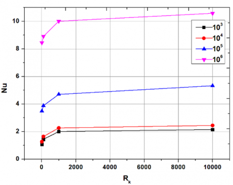
The study extends to focus on the conductivity ratio's impact on the heat transmission phenomena. This was accomplished using a square chamber filled with a 03/0.7 Al2O3/water nanofluid for Hf=0.5 and Lf=0.75. Figure 13 depicts the same plot. The Nusselt number rises as the conductivity ratio, Rk, increases. This relationship holds valid for every Ra number ranging from 103 to 106.
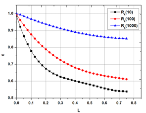
Finally, the impact of conductivity ratios on the temperature distribution over the length of the fin as seen in Figure 14 is investigated.
Figure 13. Comparison of Nu vs Rk at various Ra with 30% aluminium oxide nano particles in water and fin at Lf=0.75 & Hf=0.5
Figure 14. Temperature distribution vs length of the fin at various conductivity ratio values
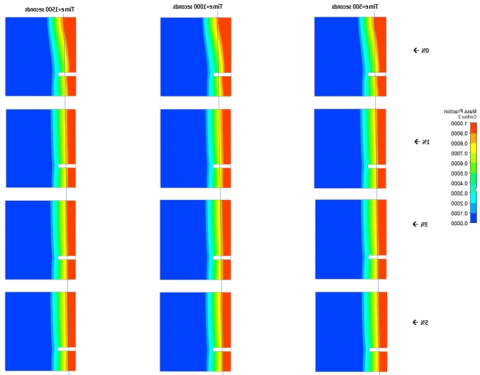
Figure 15. Variation of melt fraction with different time steps
From the Figure 15, it is clearly understanding that, the higher the Rk, the lower is the temperature difference along the length of the fin. Comparing Rk=10 and 1000, the reduction in the first case is 47% while it is only 15% for the last case. This implies the apparent that a fin with a larger Rk value will provide more heat enhancement [31-35].
3.4 Influence of nano additives on heat flow
By analysing quantitatively, the melting of PCM with and Without nanoparticles the following results are observed. There was a high rate of melting initially for about 1500-time steps i.e., around 300 seconds. This rate of melting increased with increase in nano particle concentration. After that when the melt fraction remained almost constant as the equilibrium is being approached the rate remained constant for all concentrations.
The Al2O3-nanofluid used in this study was poured into a square chamber with a horizontal fin for heat enhancement and was subjected to a numerical examination. While horizontal walls are kept adiabatic (or insulated), sidewalls are kept at a constant temperature (the hotter wall is kept at 310 K, while the cooler wall is kept at 290 K). There are nine potential length and position combinations that have been looked at for the horizontal fin, which is attached to the heated wall. The fluctuation in the Nusselt number of Al2O3 nanoparticles at a 3% volume concentration in water, a combination of water and Ethylene Glycol, and Ethylene Glycol is determined. It is found that when the wall temperature rises, the Rayleigh number increases, resulting in increased activity and therefore improved heat transmission. Additionally, when the volume percentage of EG is increased from 0% to 100%, the stream function approaches the isothermal walls, increasing thermal transmission. Additionally, it is found that the optimum fin location is H=0.5 & L=0.75. The greater the conductivity ratio, the more effective the heat augmentation is. Thus, the author finds that incorporating fins into a square cavity filled with nanofluids improves heat transmission.
[1] Dagtekin, I., Oztop, H.F. (2001). Natural convection heat transfer by heated partitions within enclosure. International Communications in Heat and Mass Transfer, 28(6): 823-834. https://doi.org/10.1016/S0735-1933(01)00286-X
[2] Saghir, M.Z., Ahadi, A., Yousefi, T., Farahbakhsh, B. (2016). Two-phase and single-phase models of flow of nanofluid in a square cavity: Comparison with experimental results. International Journal of Thermal Sciences, 100: 372-380. https://doi.org/10.1016/j.ijthermalsci.2015.10.005
[3] Khanafer, K., Vafai, K., Lightstone, M. (2003). Buoyancy-driven heat transfer enhancement in a two-dimensional enclosure utilizing nanofluids. International Journal of Heat and Mass Transfer, 46(19): 3639-3653. https://doi.org/10.1016/S0017-9310(03)00156-X
[4] Li, H., Xiao, X., Wang, Y., Lian, C., Li, Q., Wang, Z. (2020). Performance investigation of a battery thermal management system with microencapsulated phase change material suspension. Applied Thermal Engineering, 180: 115795. https://doi.org/10.1016/j.applthermaleng.2020.115795
[5] Chen, T.H., Chen, L.Y. (2007). Study of buoyancy-induced flows subjected to partially heated sources on the left and bottom walls in a square enclosure. International Journal of Thermal Sciences, 46(12): 1219-1231. https://doi.org/10.1016/j.ijthermalsci.2006.11.021
[6] Hwang, K.S., Lee, J.H., Jang, S.P. (2007). Buoyancy-driven heat transfer of water-based Al2O3 nanofluids in a rectangular cavity. International Journal of Heat and Mass Transfer, 50(19-20): 4003-4010. https://doi.org/10.1016/j.ijheatmasstransfer.2007.01.037
[7] Putra, N., Roetzel, W., Das, S.K. (2003). Natural convection of nano-fluids. Heat and Mass Transfer, 39(8-9): 775-784. https://doi.org/10.1007/s00231-002-0382-z
[8] Nimmagadda, R., Venkatasubbaiah, K. (2015). Conjugate heat transfer analysis of micro-channel using novel hybrid nanofluids (Al2O3+ Ag/Water). European Journal of Mechanics-B/Fluids, 52: 19-27. https://doi.org/10.1016/j.euromechflu.2015.01.007
[9] Ho, C.J., Liu, W.K., Chang, Y.S., Lin, C.C. (2010). Natural convection heat transfer of alumina-water nanofluid in vertical square enclosures: An experimental study. International Journal of Thermal Sciences, 49(8): 1345-1353. https://doi.org/10.1016/j.ijthermalsci.2010.02.013
[10] Frederick, R.L. (1989). Natural convection in an inclined square enclosure with a partition attached to its cold wall. International Journal of Heat and Mass Transfer, 32(1): 87-94. https://doi.org/10.1016/0017-9310(89)90093-8
[11] Bilgen, E. (2005). Natural convection in cavities with a thin fin on the hot wall. International Journal of Heat and Mass Transfer, 48(17): 3493-3505. https://doi.org/10.1016/j.ijheatmasstransfer.2005.03.016
[12] Shi, X., Khodadadi, J.M. (2003). Laminar natural convection heat transfer in a differentially heated square cavity due to a thin fin on the hot wall. Journal of Heat and Mass Transfer, 125(4): 624-634. https://doi.org/10.1115/1.1571847
[13] Frederick, R.L., Valencio, A. (1989). Heat transfer in a square cavity with a conducting partition on its hot wall. International Communications in Heat and Mass Transfer, 16(3): 347-354. https://doi.org/10.1016/0735-1933(89)90083-3
[14] Nag, A., Sarkar, A., Sastri, V.M.K. (1993). Natural convection in a differentially heated square cavity with a horizontal partition plate on the hot wall. Computer Methods in Applied Mechanics and Engineering, 110(1-2): 143-156. https://doi.org/10.1016/0045-7825(93)90025-S
[15] Tasnim, S.H., Collins, M.R. (2004). Numerical analysis of heat transfer in a square cavity with a baffle on the hot wall. International Communications in Heat and Mass Transfer, 31(5): 639-650. https://doi.org/10.1016/S0735-1933(04)00051-X
[16] Mohamed, S.A., Al-Sulaiman, F.A., Ibrahim, N.I., Zahir, M.H., Al-Ahmed, A., Saidur, R., Yılbaş, B.S., Sahin, A.Z. (2017). A review on current status and challenges of inorganic phase change materials for thermal energy storage systems. Renewable and Sustainable Energy Reviews, 70: 1072-1089. https://doi.org/10.1016/j.rser.2016.12.012
[17] Janjanam, N., Nimmagadda, R., Asirvatham, L.G., Harish, R., Wongwises, S. (2021). Conjugate heat transfer performance of stepped lid-driven cavity with Al2O3/water nanofluid under forced and mixed convection. SN Applied Sciences, 3(6): 605. https://doi.org/10.1007/s42452-021-04592-7
[18] Jahanpanah, M., Sadatinejad, S.J., Kasaeian, A., Jahangir, M.H., Sarrafha, H. (2021). Experimental investigation of the effects of low-temperature phase change material on single-slope solar still. Desalination, 499: 114799. https://doi.org/10.1016/j.desal.2020.114799
[19] Nimmagadda, R., Chereches, E.I., Chereches, M. (2021). Heat transfer performance of uni-directional and bi-directional lid-driven cavities using nanoparticle enhanced ionic liquids (NEILS). International Journal of Thermophysics, 42: 1-18. https://doi.org/10.1007/s10765-021-02814-z
[20] Lv, Y., Yang, X., Zhang, G. (2020). Durability of phase-change-material module and its relieving effect on battery deterioration during long-term cycles. Applied Thermal Engineering, 179: 115747. https://doi.org/10.1016/j.applthermaleng.2020.115747
[21] Abdulmunem, A.R., Samin, P.M., Rahman, H.A., Hussien, H.A., Mazali, I.I. (2020). Enhancing PV cell’s electrical efficiency using phase change material with copper foam matrix and multi-walled carbon nanotubes as passive cooling method. Renewable Energy, 160: 663-675. https://doi.org/10.1016/j.renene.2020.07.037
[22] Yun, S., Lee, S.H., Song, K.S., Cho, W., Kim, Y. (2020). Performance improvement of tailored die quenching using material combinations with phase change material in hot stamping. International Journal of Heat and Mass Transfer, 161: 120286. https://doi.org/10.1016/j.ijheatmasstransfer.2020.120286
[23] Shakerin, S., Bohn, M., Loehrke, R.I. (1988). Natural convection in an enclosure with discrete roughness elements on a vertical heated wall. International Journal of Heat and Mass Transfer, 31(7): 1423-1430. https://doi.org/10.1016/0017-9310(88)90251-7
[24] Park, J., Shin, D.H., Shin, Y., Karng, S.W. (2019). Analysis of heat transfer in latent heat thermal energy storage using a flexible PCM container. Heat and Mass Transfer, 55: 1571-1581. https://doi.org/10.1007/s00231-018-02534-5
[25] Longeon, M., Soupart, A., Fourmigué, J.F., Bruch, A., Marty, P. (2013). Experimental and numerical study of annular PCM storage in the presence of natural convection. Applied Energy, 112: 175-184. https://doi.org/10.1016/j.apenergy.2013.06.007
[26] Dukhan, W.A., Dhaidan, N.S., Al-Hattab, T.A. (2020). Experimental investigation of the horizontal double pipe heat exchanger utilized phase change material. IOP Conference Series: Materials Science and Engineering, 671(1): 012148. https://doi.org/10.1088/1757-899X/671/1/012148
[27] Avci, M., Yazici, M.Y. (2013). Experimental study of thermal energy storage characteristics of a paraffin in a horizontal tube-in-shell storage unit. Energy Conversion and Management, 73: 271-277. https://doi.org/10.1016/j.enconman.2013.04.030
[28] Liu, C., Du, P., Fang, B., Li, Z., Chen, B., Rao, Z. (2020). Experimental study on a functional microencapsulated phase change material for thermal management. International Communications in Heat and Mass Transfer, 118: 104876. https://doi.org/10.1016/j.icheatmasstransfer.2020.104876
[29] Liu, Z., Tang, B., Zhang, S. (2020). Novel network structural PEG/PAA/SiO2 composite phase change materials with strong shape stability for storing thermal energy. Solar Energy Materials and Solar Cells, 216: 110678. https://doi.org/10.1016/j.solmat.2020.110678
[30] Nguyen, H.Q., Shabani, B. (2020). Metal hydride thermal management using phase change material in the context of a standalone solar-hydrogen system. Energy Conversion and Management, 224: 113352. https://doi.org/10.1016/j.enconman.2020.113352
[31] Sheng, X., Dong, D., Lu, X., Zhang, L., Chen, Y. (2020). MXene-wrapped bio-based pomelo peel foam/polyethylene glycol composite phase change material with enhanced light-to-thermal conversion efficiency, thermal energy storage capability and thermal conductivity. Composites Part A: Applied Science and Manufacturing, 138: 106067. https://doi.org/10.1016/j.compositesa.2020.106067
[32] Ghalambaz, M., Zadeh, S.M.H., Mehryan, S.A.M., Pop, I., Wen, D. (2020). Analysis of melting behavior of PCMs in a cavity subject to a non-uniform magnetic field using a moving grid technique. Applied Mathematical Modelling, 77: 1936-1953. https://doi.org/10.1016/j.apm.2019.09.015
[33] Ghalambaz, M., Zhang, J. (2020). Conjugate solid-liquid phase change heat transfer in heatsink filled with phase change material-metal foam. International Journal of Heat and Mass Transfer, 146: 118832. https://doi.org/10.1016/j.ijheatmasstransfer.2019.118832
[34] Ghalambaz, M., Mehryan, S.A.M., Zahmatkesh, I., Chamkha, A. (2020). Free convection heat transfer analysis of a suspension of nano–encapsulated phase change materials (NEPCMs) in an inclined porous cavity. International Journal of Thermal Sciences, 157: 106503. https://doi.org/10.1016/j.ijthermalsci.2020.106503
[35] Mehryan, S.A.M., Ghalambaz, M., Gargari, L.S., Hajjar, A., Sheremet, M. (2020). Natural convection flow of a suspension containing nano-encapsulated phase change particles in an eccentric annulus. Journal of Energy Storage, 28: 101236. https://doi.org/10.1016/j.est.2020.101236