Ouf A. Shams*![]() | Bassam Ali Ahmed
| Bassam Ali Ahmed![]() | Hasan Shakir Majdi
| Hasan Shakir Majdi![]()
© 2023 IIETA. This article is published by IIETA and is licensed under the CC BY 4.0 license (http://creativecommons.org/licenses/by/4.0/).
OPEN ACCESS
This research paper presents a study and a numerical investigation on the effect of the thickness of the samples on the crack growth as well as the phenomenon of fatigue. As well as the type of alloy used to withstand these physical deformations. Types of samples were designed from aluminum alloys 2024 and 7085 and compared with each other in bearing crack growth as well as the phenomenon of fatigue. The thermal effect was also seen on it by adjusting the temperature value in two cases, 20℃ and 40℃. Where an additional processor was added to the Ansys program, which worked on the growth of the crack in a manner consistent with the phenomenon of fatigue. Where a pressure value of 4.8 MPa was applied from one side of the sample and it was fixed from the other side, where a time of 8000 s was taken. Where the results showed that the maximum deformation that was reached was 0.56 mm in the case where the thickness of the sample was 5 mm and the type of metal was aluminum alloy 7085. The value of bone deformation at a thickness of 5 mm is 0.66 mm, which is the highest value of deformation compared to the other cases. Aluminum alloy 7085 has reached a crack growth of 7.5 mm during 2777 cycles. While alloy 2024 has reached the same crack growth during 32784 cycles. The true meaning of the difference in properties between alloys can only be understood by comparing the mechanical properties of different alloys. Comparison of aluminum alloy 6061 with case with 3 mm primitive crack growth and 90 degree crack angle.
fatigue life, dynamic crack propagation, crack tip, analysis, aluminum alloy 2024, aluminum alloy 7085, thermal fatigue
This research presents a numerical simulation of the behavior of crack retarders coupled to integrated metallic structures. In order to simulate the different failure processes of a bonded structure and estimate the life of fatigue crack propagation, a unique modeling strategy using the finite element method has been devised. A computer interface using the industry-standard package MSC NASTRAN has been created and experimentally tested. Various strap configurations, including various strap materials, have been studied in terms of how well they can slow down crack propagation [1]. Laser treatment extended the life of AA2024-T3 sheets by 285 percent, improving their tensile and fatigue strength. The primary factor improving fatigue crack development life is the generated compressive residual stress field produced by the LH process. The loss in fatigue strength brought on by the presence of a rivet hole can be mitigated by applying just one line or two circles transverse to the loading direction [2]. Crack lengths were chosen to be 3 and 5 mm and crack angles to be 0 and 90 degrees using numerical research and experimental examination. Crack propagation was observed to rise as the crack duration rose, and to decrease as the plate's aspect ratio increased, according to the results. Practically, a rig was created and manufactured to put cycling effect loads on the center crackd plates while adjusting the temperature and monitor the dynamic crack propagation [3]. Thermally-Assisted Machining (TAM) could enhance the machinability of titanium-based alloys. TAM involves temporarily lowering metal hardness at the cutting point and reducing cutting forces. Such methods as heating with a laser beam or using a plasma flame are being considered. Cutting forces are lowered by 20% to 40% when using plasma-assisted machining, and tool life is increased by 150 times [4]. The utilization of intensity therapy and cladding is recommended as a reasonable method for controlling the heading of break proliferation and to make a break development resistant (CGP) Crack Growth Path zone on a metal plate utilizing laser-prompted line designs. We made and tried different line-design shapes on a flimsy SUS316 plate of 1 mm thickness to evaluate the effect of the line designs on break engendering [5]. Beat laser testing is utilized to direct warm weakness tests on AISI 316L(N) treated steel examples that may likewise be presented to extra static mechanical burdens. These tests are directed in a Helium air utilizing an extraordinary arrangement that is completely instrumented. The Multiview framework uncovered the time-settled surface harm processes, from impressive cyclic versatility with determined slip groups to microcrack commencement and advancement [6]. Pre-break directing laser dividing (PCGLC) is a procedure that has been depicted to resolve the issue of course deviation in hilter kilter straight silicon wafer cutting. PCGLC might gain a high handling quality with a decent kerf quality and an impartial direction through trial and reenactment tests. The none-deviation system in PCG LC is shown by a reproduction of warm crack spread [7]. A developing additive manufacturing technique called "selective laser melting" has been researched recently for processing various alloys. Process pieces must operate effectively in cyclic applications as well in order for the process to be applied to functioning components. In this work, process-induced flaws, which are crucial for fatigue loading of AlSi12 alloy parts, are examined in relation to base plate heating and post-process stress release [8]. The combined number of stacking cycles fundamental for an exhaustion break to create and engender before unexpected crack is known as the weakness life. Break proliferation issues are much of the time settled utilizing some sort of computational methodology since assessment of the weakness break engendering life in real calculations is only occasionally attainable. In this paper, it is depicted how to reproduce the spread of weariness breaks utilizing the limited component strategy (FEM) Finite Element Method and expanded limited component technique (XFEM) Expanded Finite Element Method [9]. The capacity of concrete is sometimes underestimated, particularly its ability to withstand shear stresses in slabs without stirrups. Possible reinforcing fatigue damage may be evaluated using partial damage techniques with comparable failure loads to those used for steel structures. Modern measuring technology allows for the verification of actual strain and stress ranges, which may be much less than those determined by conservative design models [10]. Overdesign is becoming a less viable alternative for the most recent HPHT High Pressure High Temperature oilfield equipment. As equipment is stressed by very high internal pressures and material strength is being reduced by rising temperatures, fatigue and rapid crack are becoming the most problematic design failure modes. To obtain safe, dependable, and economically advantageous equipment designs, more stringent stress analysis and design techniques are required [11]. Using 6082 T651 aluminum alloy in fatigue experiments with a straightforward loading pattern that was predicted to accelerate crack formation, new data are reported. Cracks were studied by using direct current potential drop and optical methods to track crack growth. Electrical resistance strain gauges were also used to determine the existence of crack closure [12]. There is local thermal heating or cooling at the tip of the cut by a thermal source in many technical processes that include cutting or welding. In this article, we analyze the stress distribution caused by a point heat source travelling over an infinite elastic plate at a constant speed. The theory that is currently being developed is shown using certain strength difficulties of thermal beam cutting of brittle materials as an example [13]. For the 2024-T351 aluminum combination, a basic aggregate plastic type of 110% was found by contrasting plane strain mathematical gauges with the exploratory worth of da/dN for a break length of 26.5 mm and a pressure proportion of 0.1. Breaks were unaffected by varieties in pressure proportion and stress state, demonstrating that their impacts on break tip plastic twisting are irrelevant. For the 18Ni300 maraging steel and the 7050-T6 aluminum amalgam, individually, FCG Fatigue Crack Growth rate was similarly expected, and slants of m = 3.09 and 2.70 were found for particular bends [14]. The presence of strain gradients causes an elastic zone to exist near the tip of a stationary crack. At the crack tip, an elastic singularity creates forces that are high enough to trigger quasi-cleavage. These predictions mimic discrete dislocation calculations in terms of quality, including the idea of a dislocation-free zone near the crack tip [15]. The Bound together Methodology binds together the way of behaving of both short and long breaks by representing the two captures. Short breaks frequently foster within the sight of pressure fixations that are either previous or in-situ delivered by the exhaustion harm, as opposed to the extensive cracks. Slip groups, interruptions, expulsions, separation heap ups are instances of pressure cycling that outcome from weariness cycling [16]. SLM Selective Laser Melting, a powder-bed combination added substance fabricating innovation, can create three-layered complex items with mechanical characteristics comparable to or better than those got by traditional creation. Anisotropic mechanical qualities and interaction initiated leftover anxieties are issues for metallic items created with SLM. In both as-constructed and stress-alleviated circumstances, the impact of lingering weights on the weariness break advancement pace of SLM Ti6Al4V is analyzed [17]. One of the first of these combinations, called the "Cantor composite," has elastic qualities of 1 GPa and break sturdiness values more than 200 MPa. These mechanical characteristics likewise tend to turn out to be better at cryogenic temperatures. Generally speaking, it was found that this composite's weakness conduct was prevalent to, or possibly practically identical to, conventional cryogenic and TWIP Twinning-Induced Plasticity prepares [18]. An expansion of the notable Paris regulation for break proliferation is given, showing a more complete "bound together rule" that could represent a portion of the takeoffs from the power-regulation system. Specifically, the pressure force part K(a) is supplanted with a fitting mean across a material/primary boundary length scale a, the "crack quantum". The idea is a consistent expansion of first creator's latest, fruitful ideas about static disappointment and interminable life expectancies [19]. The comparative analysis of aluminum alloys 2024 and 7085 under thermal fatigue and crack propagation has practical implications in industries such as aerospace, automotive, marine, power generation, and material science research. It enables engineers and researchers to make informed decisions regarding material selection, design optimization, and the development of more durable and reliable components and structures. The properties and behavior of aluminum alloys can vary between different batches, suppliers, or manufacturing processes. Ensuring consistent and representative test samples is essential for accurate comparative analysis. It is important to carefully control and document the material properties and characteristics of the alloys being studied. this comparative analysis is to provide insights into the relative performance and behavior of aluminum alloys 2024 and 7085 under thermal fatigue and crack propagation conditions. The findings can be valuable for industries that utilize these alloys, helping in material selection, design optimization, and enhancing the durability and reliability of aluminum components subjected to cyclic thermal loading.
The aim of this work is to study the effect of sample thickness and fatigue phenomenon on deformations that occur as a result of crack growth. In order to achieve this goal, the following objectives are achieved:
- Investigate the influence of varying temperature conditions on the deformation and crack growth rates in different aluminum alloys
- Study the effect of thickness change on deformation and crack growth
- Study the effect of the type of aluminum alloy on deformation and crack growth
- Validate the study
The aim of this study is to conduct a comparative analysis of the behavior of aluminum alloys 2024 and 7085 under conditions of thermal fatigue and investigate their crack growth and deformation characteristics. The specific objectives are to examine the crack initiation and propagation mechanisms, evaluate the effects of thermal cycling on crack growth rates, and compare the fatigue life and crack growth resistance of the two alloys. The study aims to provide insights into the performance and durability of these alloys under thermal loading conditions and contribute to the understanding of their suitability for applications involving thermal fatigue and crack propagation.
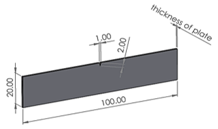
The process of simulating crack growth requires an engineering program capable of designing the required model with precise geometric dimensions. Where the SOLIDWORKS program was used to design the samples. Samples of aluminum alloys with a length of 100 mm and a width of 20 mm were used, and the thickness used for the cases varies from 1 mm, 3 mm, and 5 mm. As for the growth of the crack, the used crack had a length of 2 mm and the base of the triangle was 1 mm, so that the crack began at the middle of the sample, as shown in Figure 1.
The simulation setup and methodology employed in this study aimed to replicate realistic loading and environmental conditions, as well as capture the crack growth behavior observed in experimental studies. By combining numerical simulations with experimental data, we aimed to enhance the understanding of thermal fatigue and crack propagation in these aluminum alloys and provide valuable information for material selection and design optimization in industries where these alloys are extensively used.
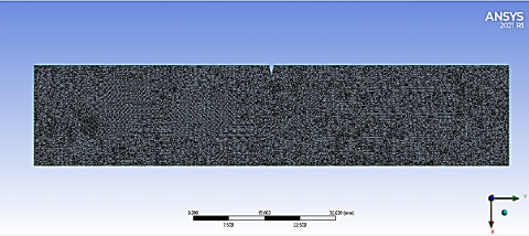
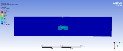
After designing the model, a high-resolution simulation should be done. To ensure the quantity of the component, the mesh independency must be used, that is, the increase in the number of the element to reach stable results that do not change with the increase. The element number value reached 945279 with a maximum deformation of 0.33 mm, as shown in Table 1. An element size of 0.1 mm was used as shown in Figure 2.
Figure 1. Geometry
Table 1. Mesh independency
|
Case |
Element |
Node |
Maximum Deformation (mm) |
|
1 |
312076 |
513293 |
0.82 |
|
2 |
512342 |
735432 |
0.41 |
|
3 |
734432 |
1065543 |
0.34 |
|
4 |
945279 |
1386721 |
0.33 |
Figure 2. Geometry mesh
Where an additional processor was added to the Ansys program, which worked on the growth of the crack in a manner consistent with the phenomenon of fatigue. Where a pressure value of 4.8 MPa was applied from one side of the sample and it was fixed from the other side, where a time of 8000 s was taken [1]. As for the materials that were used, they are aluminum alloys 2024 and 7085 taken from the research [1]. Where variable temperatures were applied to the sample to see the effect of deformations and crack growth on it, and the temperatures were 20 and 40℃ because it is within the natural conditions of the atmosphere.
The overall equilibrium equations for linear structural static analysis are:
$[K]\{u\}=\{F\}$ (1)
or
$[K]\{u\}=\left\{F^a\right\}+\left\{F^r\right\}$ (2)
where:
[K] = $\sum_{m=1}^N$ $\left[K_e\right]$ = total stiffness matrix
{u} = nodal dislodging vector
N = number of elements
[Ke] = element stiffness matrix (may include the element stress stiffness matrix)
{Fr} = reaction load vector
$\left\{F^a\right\}$, the total applied load vector, is defined by:
$\left\{F^a\right\}=\left\{F^{n d}\right\}+\left\{F^{a c}\right\}+\sum_{m=1}^N\left(\left\{F_e^{t h}\right\}+\left\{F_e^{p r}\right\}\right)$ (3)
where:
{Fnd} = applied nodal load vector
$\left\{F^{a c}\right\}=-[M]\left\{a_c\right\}$ = acceleration load vector
$[M]=\sum_{m=1}^N\left[M_e\right]$ = total mass matrix
[Me] = element mass matrix (described in Derivation of Structural Matrices)
$\left\{a_c\right\}$ = total acceleration vector (defined in Acceleration Effect)
$\left\{F_e^{t h}\right\}$ = element thermal load vector (described in Derivation of Structural Matrices)
$\left\{F_e^{p r}\right\}$ = component pressure load vector (portrayed in Deduction of Underlying Networks)
Consider a one-component segment model that is exclusively stacked by its own load to exhibit the heap vectors. Response Burden Vectors and Applied Burden Vectors Albeit the lower applied gravity load is applied straightforwardly to the forced relocation thus doesn't make strain, it contributes similarly as a lot to the response load vector as the higher applied gravity load. In addition, any applied burdens on a specific DOF degree of freedom are ignored assuming the solidness for that DOF is 0.
The implementation of these governing equations in our methodology enables us to establish a quantitative framework for analyzing crack propagation and evaluating the fatigue behavior of aluminum alloys 2024 and 7085. By connecting the theoretical principles with the practical implementation, we ensure that our research findings are grounded in sound scientific principles and provide valuable insights into the comparative analysis of these alloys under thermal fatigue conditions.
5.1 Effect of temperature change on deformation and crack growth
When a material is subjected to temperature changes, it undergoes thermal expansion or contraction. This expansion or contraction can lead to changes in dimensional stability and induce stresses within the material. Differential expansion between different components or phases can result in the initiation or acceleration of cracks. Temperature changes can induce thermal stresses in materials. These stresses arise due to the mismatch in coefficients of thermal expansion between different materials or within the same material. Thermal stress can promote crack initiation, propagation, and affect the crack behavior of materials. Temperature changes can have a significant impact on the ductility and toughness of materials. Generally, materials tend to exhibit increased ductility and toughness at lower temperatures and reduced ductility and toughness at higher temperatures. This behavior is associated with changes in dislocation mobility, phase transformations, and the ability to absorb and dissipate energy during deformation and crack. Temperature changes can induce phase transformations in certain materials. These transformations may involve changes in crystal structure, mechanical properties, and even volume changes. Phase transformations can influence deformation mechanisms, alter the crack behavior, and affect crack growth rates. Repeated temperature cycling, known as thermal fatigue, can cause cumulative damage and promote crack growth in materials. The cyclic expansion and contraction induce varying stress states, leading to fatigue crack initiation and subsequent growth. The rate of crack growth under thermal fatigue conditions depends on factors such as temperature range, loading frequency, and material properties. Many materials undergo a transition from brittle to ductile behavior with increasing temperature. At low temperatures, materials tend to exhibit brittle crack behavior, characterized by rapid crack propagation. As the temperature rises, the materials become more ductile, with increased resistance to crack growth and improved energy absorption capacity.
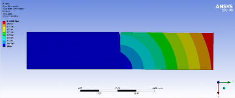
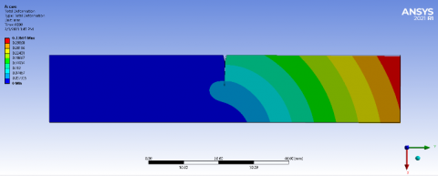
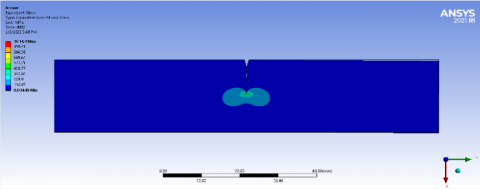
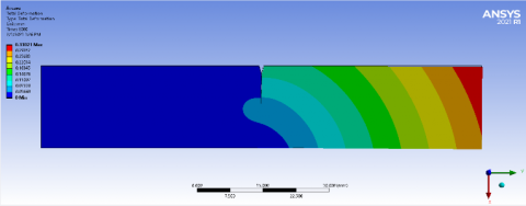
The temperature change in the material helps to expand the internal molecules of the aluminum alloy, and thus the crack growth increases. Through Figure 3, it is noted that the deformation values increase with increasing temperatures in the temperature of 20℃. The maximum deformation that was reached was 0.56 mm in the case where the thickness of the sample was 5 mm and the type of metal was aluminum alloy 7085. As for the temperature of 40, the deformation value It increased on the same type of metal and thickness and reached 0.58 mm.
Figure 3. Deformation contour for thickness plate 5 mm and aluminum alloy 7085 at, (a) 20℃, (b) 40℃
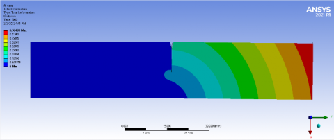
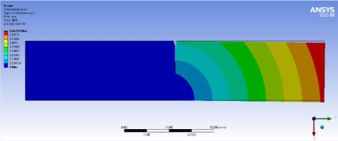
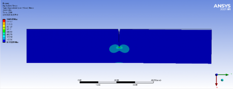
Figure 4. Stress contour for thickness plate 5 mm and aluminum alloy 7085 at, (a) 20℃, (b) 40℃
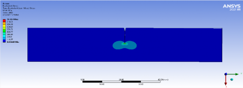
As for Figure 4, which shows the details of the stresses as a result of the applied pressure and at different temperatures, it is noted that the value of the stresses increases with the increase in temperature. In the case where the temperature is 20℃, the deformation value is 1441 MPa, but in the case where the sample temperature is 40℃ the deformation value was 1448 MPa. This rise indicates the importance of temperature for crack growth.
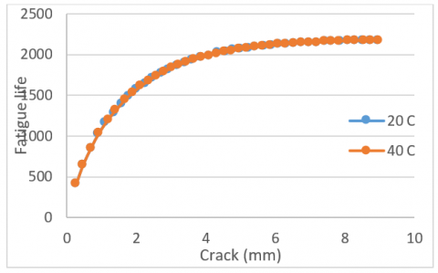
Figure 5 represents a chart showing the apparent fatigue cycles with the growth of the crack, and through it is noted that the temperature value has a significant impact on the long term. As the temperature increased the value of crack growth until it reached 9.1 mm, while the temperature was 20℃, the value of crack growth was 8.9 mm.
Figure 5. Fatigue life with crack for thickness plate 5 mm and aluminum alloy 7085 at 20℃, 40℃
5.2 Effect of temperature change on deformation and crack growth
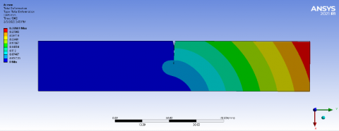
The change in the thickness of the sample helps to withstand the phenomenon of fatigue and the growth of the crack that is generated as a result of the added load through Figure 6. It is noted that the deformation value increases with the increase in the thickness of the sample due to the growth of the crack. Where the value of deformation in the thickness was 1 mm 0.33 mm when the temperature of the sample was 20℃ and the type of metal was aluminum alloy 7085. As for the thickness of 3 mm, the value of deformation was 0.56 mm, while in the case where the thickness of the sample was 5 mm, the value of bone deformation was 0.66 mm, which is the highest value of deformation compared to the other cases.
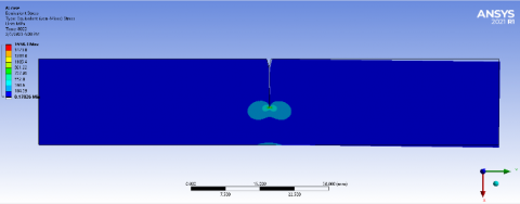
Figure 6. Deformation contour for temperature plate 20℃ and aluminum alloy 7085 at, (a) thickness plate 1 mm, (b) thickness plate 3 mm, (c) thickness plate 5 mm
As for the stresses, they also increase with the increase in the thickness of the sample as a result of the high load on it. Through Figure 7, it is noted that the value of the stresses when the thickness of the sample is 1 mm, the value of the stress was 1034 MPa, and in the case where the thickness of the sample was 3 mm, the value of the stresses was 1441 MPa. In the last case, in which the value of the stresses reached 1658 MPa, it was at a thickness of 5 mm, which is the highest value of the stresses compared to the other cases.
Figure 7. Stress contour for temperature plate 20℃ and aluminum alloy 7085 at, (a) thickness plate 1 mm, (b) thickness plate 3 mm, (c) thickness plate 5 mm
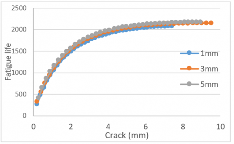
Figure 8 shows the effect of changing the thickness of the samples on the value of crack growth as well as the apparent fatigue cycles. Where it is noted that the value of crack growth decreases with increasing the thickness of the samples. For the thickness of 1 mm, it took a large number of tools to reach a crack growth of 7.6 mm, while the thickness of 3 mm had reached a high crack growth, but with a high number of fatigue cycles as well.
Figure 8. Fatigue life with crack for temperature plate 20℃ and aluminum alloy 7085 at 1 mm, 3 mm, 5 mm
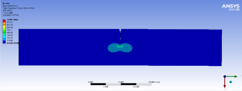
Figure 9. Deformation contour for temperature plate 20℃ and thickness plate 1 mm at, (a) aluminum alloy 2024, (b) aluminum alloy 7085
Figure 10. Stress contour for temperature plate 20℃ and thickness plate 1 mm at, (a) aluminum alloy 2024, (b) aluminum alloy 7085
5.3 Effect of the type of aluminum alloy on deformation and crack growth
The mechanical properties of metals vary greatly with the same alloy, as aluminum alloy 7085 is weak compared to alloy 2024. This is shown by Figures 9 and 10 through the forms of deformations and stresses.
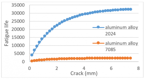
Figure 11 shows the true meaning of the difference in properties between alloys, as aluminum alloy 7085 has reached a crack growth of 7.5 mm during 2777 cycles, while alloy 2024 has reached the same crack growth during 32784 cycles.
Figure 11. Fatigue life with crack for temperature plate 20℃ and thickness plate 1 mm at aluminum alloy 7085, aluminum alloy 7085
5.4 Validation
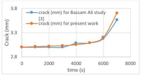
The comparison process is achieved through previous research that bears the same practical importance for the work presented, where a case was taken from the cases that were used in the research [3], compared and the results obtained were presented. Where the comparison was made with the case that bears the properties of aluminum alloy 6061 and the length of the primitive crack growth is 3 mm, as well as the crack angle of 90 degrees.
Figure 12. Time with crack for Bassam [3] experimental study and present work
Through Figure 12, we notice the great convergence in the obtained results, and this reached an error rate of no more than 5%.
1. The maximum deformation that was reached was 0.56 mm in the case where the thickness of the sample was 5 mm and the type of metal was aluminum alloy 7085. The temperature change in the material helps to expand the internal molecules of the aluminum alloy, and thus the crack growth increases. Fatigue cycles with the growth of the crack, and through it is noted that the temperature value has a significant impact on the long term.
2. The deformation value increases with the increase in the thickness of the sample due to the growth of the crack. The value of bone deformation at a thickness of 5 mm is 0.66 mm, which is the highest value of deformation compared to the other cases. The stresses increase as a result of the high load placed on the samples.
3. Aluminum alloy 7085 has reached a crack growth of 7.5 mm during 2777 cycles, while alloy 2024 has reached the same crack growth during 32784 cycles. The true meaning of the difference in properties between alloys can only be understood by comparing the mechanical properties of different alloys.
4. The results of a study on the properties of aluminum alloy 6061, where the length of the primitive crack growth is 3 mm, as well as the crack angle of 90 degrees, are presented. The comparison process is achieved through previous research that bears the same practical importance for the work presented, and this reached an error rate of no more than 5%.
5. The results obtained from this comparative analysis contribute to the existing knowledge base and can serve as a valuable reference for researchers, engineers, and designers working in the field of structural integrity, material selection, and fatigue analysis. The findings can aid in the development of improved design guidelines, predictive models, and materials with enhanced resistance to thermal fatigue and crack propagation.
6. By discussing these possible future research directions, the authors can demonstrate the broader implications of their findings and inspire further investigations that build upon their work, ultimately advancing the understanding and application of aluminum alloys under thermal fatigue and crack propagation conditions.
[1] Boscolo, M., Allegri, G., Zhang, X. (2008). Design and modelling of selective reinforcements for integral aircraft structures. AIAA Journal, 46(9): 2323-2331. https://doi.org/10.2514/1.35712
[2] Kashaev, N., Groth, A., Ventzke, V., Horstmann, M., Riekehr, S., Staron, P., Huber, N. (2021). Effect of laser heating on mechanical properties, residual stresses and retardation of fatigue crack growth in AA2024. Fatigue & Fracture of Engineering Materials & Structures, 44(4): 887-900. https://doi.org/10.1111/ffe.13400
[3] Ahmed, B.A., Alshamma, F.A. (2020). Dynamic crack propagation in thin plates under cycling thermal stresses effect with cycling impact loading. Journal of Mechanical Engineering Research and Developments, 43(7): 1-11.
[4] Shams, O.A. (2020). Machinability improvement of hard-to-machine materials by monitoring and controlling laser heating. Doctoral dissertation, Curtin University.
[5] Jo, Y.K., Yu, J.H., Lee, K.Y., Shim, D.S., Park, S.H. (2020). Control of crack propagation on SUS316 plate by laser-induced patterning: Heat treatment and cladding. Journal of Mechanical Science and Technology, 34: 4711-4719. https://doi.org/10.1007/s12206-020-1028-0
[6] Wang, Y., Charbal, A., Hild, F., Roux, S., Vincent, L. (2019). Crack initiation and propagation under thermal fatigue of austenitic stainless steel. International Journal of Fatigue, 124: 149-166. https://doi.org/10.1016/j.ijfatigue.2019.02.036
[7] Cheng, X., Yang, L., Wang, M., Cai, Y., Wang, Y., Ren, Z. (2019). Laser beam induced thermal-crack propagation for asymmetric linear cutting of silicon wafer. Optics & Laser Technology, 120: 105765. https://doi.org/10.1016/j.optlastec.2019.105765
[8] Siddique, S., Imran, M., Walther, F. (2017). Very high cycle fatigue and fatigue crack propagation behavior of selective laser melted AlSi12 alloy. International Journal of Fatigue, 94: 246-254. https://doi.org/10.1016/j.ijfatigue.2016.06.003
[9] Rege, K., Lemu, H.G. (2017). A review of fatigue crack propagation modelling techniques using FEM and XFEM. In IOP Conference Series: Materials Science and Engineering, 276(1): 012027. https://doi.org/10.1088/1757-899X/276/1/012027
[10] Elfgren, L. (2015). Fatigue Capacity of Concrete Structures: Assessment of Railway Bridges. Luleå Tekniska Universitet.
[11] Skeels, B. (2013). Design guideline strategies for HPHT equipment. Paper Presented at the Offshore Technology Conference, Houston, Texas, USA. https://doi.org/10.4043/23943-ms
[12] Doré, M.J., Maddox, S.J. (2013). Accelerated fatigue crack growth in 6082 T651 aluminium alloy subjected to periodic underloads. Procedia Engineering, 66: 313-322. https://doi.org/10.1016/j.proeng.2013.12.086
[13] Kotousov, A. (2000). Thermal stresses and fracture of thin plates during cutting and welding operations. International Journal of Fracture, 103: 361-372. https://doi.org/10.1023/A:1007674623758
[14] Borges, M.F., Neto, D.M., Antunes, F.V. (2020). Numerical simulation of fatigue crack growth based on accumulated plastic strain. Theoretical and Applied Fracture Mechanics, 108: 102676. https://doi.org/10.1016/j.tafmec.2020.102676
[15] Martínez-Pañeda, E., Deshpande, V.S., Niordson, C.F., Fleck, N.A. (2019). The role of plastic strain gradients in the crack growth resistance of metals. Journal of the Mechanics and Physics of Solids, 126: 136-150. https://doi.org/10.1016/j.jmps.2019.02.011
[16] Sadananda, K., Babu, M.N., Vasudevan, A.K. (2019). A review of fatigue crack growth resistance in the short crack growth regime. Materials Science and Engineering: A, 754: 674-701. https://doi.org/10.1016/j.msea.2019.03.102
[17] Syed, A.K., Ahmad, B., Guo, H., Machry, T., Eatock, D., Meyer, J., Fitzpatrick, M.E., Zhang, X. (2019). An experimental study of residual stress and direction-dependence of fatigue crack growth behaviour in as-built and stress-relieved selective-laser-melted Ti6Al4V. Materials Science and Engineering: A, 755: 246-257. https://doi.org/10.1016/j.msea.2019.04.023
[18] Thurston, K.V., Gludovatz, B., Yu, Q., Laplanche, G., George, E.P., Ritchie, R.O. (2019). Temperature and load-ratio dependent fatigue-crack growth in the CrMnFeCoNi high-entropy alloy. Journal of Alloys and Compounds, 794: 525-533. https://doi.org/10.1016/j.jallcom.2019.04.234
[19] Pugno, N., Ciavarella, M., Cornetti, P., Carpinteri, A. (2006). A generalized Paris’ law for fatigue crack growth. Journal of the Mechanics and Physics of Solids, 54(7): 1333-1349. https://doi.org/10.1016/j.jmps.2006.01.007