Qingqin Meng*![]() | Chunpeng Yang
| Chunpeng Yang![]() | Hanxuan Zhou
| Hanxuan Zhou![]() | Weicai Li
| Weicai Li![]()
© 2023 IIETA. This article is published by IIETA and is licensed under the CC BY 4.0 license (http://creativecommons.org/licenses/by/4.0/).
OPEN ACCESS
In the evolving landscape of modern warfare, an escalating importance is being attributed to vehicle-mounted phased array radars due to their imperative role in information acquisition and mastery. A significant limitation to their performance lies in the challenges of heat dissipation and resultant thermal deformation of the antenna array surface. Current methodologies for predicting thermal deformation and techniques for heat dissipation exhibit inherent shortcomings, rendering them inadequate for varying radar systems and diverse operational environments. To address this, heat transfer characteristics of micro-channels on the antenna array surface of vehicle-mounted phased array radar were investigated. A novel design paradigm for the structural optimisation of the antenna array surface was subsequently proposed. In addition, a cutting-edge thermal deformation prediction method utilising a Particle Swarm Optimization (PSO)-Genetic Algorithm (GA)-Back Propagation Neural Network (BPNN) synergy was presented, aiming to overcome the deficiencies observed in existing prediction models. The insights garnered from this research offer potential pathways for the refinement of radar antenna array structures and are poised to pave the way for future advancements in this domain.
vehicle-mounted phased array radar, antenna array surface, heat dissipation, micro-channels, structural optimization, PSO (Particle Swarm Optimization)-GA (Genetic Algorithm)-BPNN (Back Propagation Neural Network), thermal deformation prediction
The intricate landscape of modern warfare underscores the paramount importance of tools capable of adept information acquisition and control. Amongst such tools, the prominence of vehicle-mounted phased array radar at strategic decision-making echelons cannot be understated [1, 2]. The optimal performance of these systems, inherently tied to the functionality of their antenna arrays, has broader ramifications for defence and surveillance systems alike [3-6].
One of the overarching challenges in ensuring consistent performance, especially in scenarios demanding prolonged operation at high outputs, is heat dissipation. Historical analyses have flagged this as a predominant limiting factor, often leading to not only system inefficiencies but also, alarmingly, catastrophic failures in certain situations [7-10].
Delving into the nuances of this problem, it becomes evident that enhancing heat dissipation mechanisms of the antenna array surface can potentially usher in a transformative change in radar systems. By bolstering their resilience against thermal stressors, the systemic reliability and stability can be notably improved. The consequent reductions in heat-induced losses and deformations would signify a paradigm shift in operational capabilities, with potential applications in a myriad of military settings [11-14].
Furthermore, a strategic overhaul in the structural dynamics of the antenna array surface might be the cornerstone in harnessing its full potential. Such optimization strategies, tailored to endure high-power operational environments, would make these systems more versatile and adaptable to the ever-evolving complexities of contemporary battlefields [15-17]. Echoing this sentiment, it becomes clear that the ramifications of these studies aren't insular; they have the potential to invigorate technological progress across a spectrum of defence-related industries.
However, despite the clear need and potential impact, a discerning look at prevalent methodologies reveals palpable gaps. Current strategies in investigating the heat dissipation conundrum in vehicle-mounted phased array radars are often deemed too risk-averse, with a tendency to default to traditional paradigms [18, 19]. This has invariably led to a lack of comprehensive insight into intricate heat transfer dynamics. Traditional analytical tools and techniques are consistently found wanting when confronted with the multi-dimensional challenges presented by these systems. In a similar vein, current techniques deployed for thermal deformation prediction have come under scrutiny for their perceived rigidity and lack of precision, thereby curtailing the broader applicability of these advanced radar systems [20, 21].
It is against this backdrop that this research venture was conceptualised. The dual-focus approach: firstly, delving into the heat transfer intricacies of micro-channels on the antenna array surface, and secondly, spearheading the development of the novel PSO-GA-BPNN method for thermal deformation prediction, represents a concerted effort to address the aforementioned challenges. The fusion of PSO, GA, and BPNN into this hybrid predictive model promises a quantum leap in terms of accuracy and operational efficiency. It is fervently hoped that the insights and innovations stemming from this study will not only reshape the architectural nuances of radar antenna arrays but also illuminate the path forward for subsequent research in this pivotal domain.
The vehicle-mounted phased array radar is an important tool to attain key information on modern battlefield, but the heat dissipation problem of antenna array has been a factor limiting its performance for a long time. With the increase of operating frequency and power, the heat generated by the antenna array will increase as well, if the heat is not dissipated in a timely manner, the accumulated heat will cause a decline in system performance, even damage the key components of the system. The heat dissipation problem of antenna array surface involves several intertwined factors, such as heat transfer, fluid dynamics, and material properties, making the design of an effective heat dissipation system a very difficult task; moreover, other factors such as the vibration of vehicle environment, the temperature fluctuations, and the space constraints can all make the design of heat dissipation even more complicated.
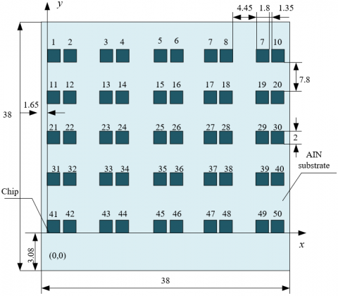
The structural optimization design of antenna array surface can cope with heat conduction and heat dissipation more effectively, thereby reducing the risk of thermal deformation. Structural optimization not only helps to improve the overall performance of the radar system, but also enhances its reliability and stability in harsh environments. Structural optimization can be achieved through multiple ways, such as choosing better heat dissipation materials, designing a more reasonable structure for the heat dissipation micro-channels, or optimizing the layout of heat sinks. But for specific application requirements and environmental conditions, the design schemes of structural optimization should be flexible, and various influencing factors should be considered. Figure 1 shows the arrangement and distribution of antenna array surface of conventional phased array radar, with each chip default as a radiation unit.
Figure 1. Arrangement and distribution of radiation units on antenna array surface of phased array radar
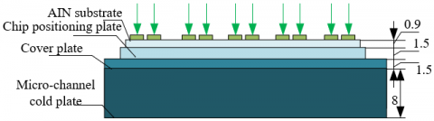
Figure 2 shows a geometric model of the micro-channel structure on the phased array surface. Linear shape, tree shape, and spiral shape are three typical structures of micro-channels on the antenna array surface of phased array radar. The linear-shaped micro-channel structure shows a straight-line arrangement that is usually parallel to the antenna array surface, its geometrical shape is simpler, and it’s easier to manufacture and maintain. This type of structure is suitable for medium-level heat dissipation needs, due to its simple structure, the heat dissipation efficiency might be insufficient in some special cases. The tree-shaped micro-channel structure has a tree-like branching channel layout that mimics the flow mechanism of fluids in nature. This structure is relatively complex and requires precise design and fabrication. Since this structure mimics natural flow, the tree-shaped structure can give a higher heat dissipation efficiency, so it can adapt to more complicated situations with higher heat dissipation requirements, but the difficulty of fabrication and maintenance is higher as well. In the spiral-shaped micro-channel structure, the micro-channels are arranged in a spiral form, in this way, the contact area between the fluid and the channel walls is increased, the geometry of the structure is more complicated, and the fabrication is more challenging. This structure increases heat dissipation efficiency via increasing fluid turbulence, so it fits better to application scenarios with higher heat dissipation requirements, but higher fabrication costs and maintenance complexity will be involved.
Figure 2. Geometric model of the micro-channel structure of phased array surface
It is a very complex process to build control equations for calculating the heat transfer of the said micro-channels since multiple assumptions will be involved. In this paper, at first, assuming: the motion of the fluid conforms to the Navier-Stokes equations and the fluid can be regarded as a continuous medium, these assumptions can simplify the fluid dynamics so that the behavior of the fluid can be described by continuous equations, and this has laid a basis for numerical calculations. Second, assuming: the flow of cooling fluid in the micro-channels is three-dimensional, steady-state and incompressible laminar flow, these assumptions ensure that the density of the fluid is constant and the flow is not time-dependent, which has significantly reduced computational complexity and allows the calculation to focus on the effects of geometry and fluid velocity distribution on heat dissipation. Third, assuming: several properties of the fluid and the solid material are constant, including thermal conductivity, viscosity, and density, and the changes in physical parameters that may be caused by temperature or pressure changes can be ignored, and these assumptions can further simplify the calculations; moreover, the friction loss (the energy loss caused by internal friction) inside the micro-channels and the heat radiation were also ignored to further simplify the computational complexity. Fourth, assuming: the liquid-solid contact surface inside the flow channels is slip-free, and this assumption makes it easier to process the interactions between fluid and solid interface, which helps to accurately simulate the fluid flow in micro-channels.
Assuming: W represents the power consumption of antenna; ϑ represents the density of cooling fluid, vo represents the specific heat capacity of cooling fluid; i, c, q respectively represents flow speed of the fluid in z, t, and x directions; Y represents temperature, then the internal heat transfer equation of the antenna array surface of vehicle-mounted phased array radar built in this study is:
$j_a\left(\frac{\partial^2 Y}{\partial z^2}+\frac{\partial^2 Y}{\partial t^2}+\frac{\partial^2 Y}{\partial x^2}\right)+W=0$ (1)
The energy equation is:
$\begin{aligned} & \vartheta v_o\left(i \frac{\partial Y}{\partial z}+c \frac{\partial Y}{\partial t}+q \frac{\partial Y}{\partial x}\right) =j_a j_a\left(\frac{\partial^2 Y}{\partial z^2}+\frac{\partial^2 Y}{\partial t^2}+\frac{\partial^2 Y}{\partial x^2}\right)+W\end{aligned}$ (2)
The specific numerical methods and calculation steps of heat transfer process of micro-channels are described in detail below. At first, the substrate, cover plate, and other solid and fluid regions were evolved, and a heat-fluid-solid three-field coupling calculation model was built. To accelerate convergence speed and save computational cost, the direct coupling method was adopted, the fluid-solid coupling interface was connected through Interface, so as to convert into the internal side of the entire computational domain, and this step ensures that the heat transfer process in the fluid-solid region is unified. Further, the 3D double-precision solver of ANSYS Fluent 16.0 was selected to perform the numerical calculations, and the SIMPLE algorithm was used to solve the coupled pressure and velocity fields. To increase convergence speed, the PRESTO format discrete pressure term was adopted to discretize the momentum and energy terms using the first-order upwind format. Then, the monitoring value of the control equations was set to 10-5 as it was taken as the convergence criterion of calculations. Numerical calculations were performed according to above settings, then the temperature distributions of fluid and solid were attained. At last, the heat dissipation performance was analyzed based on numerical results, and the micro-channel structure can be optimized according to the results.
Expressions of the inlet boundary conditions are given below:
$\frac{\partial q}{\partial x}=0, c=c_{u b}, Y=Y_{u b}$ (3)
Expressions of the outlet boundary conditions are given below:
$O=1 s y l$ (4)
Basic conditions for calculating the heat transfer of micro-channels were summarized. The HFE7200 was taken as the cooling fluid, the inlet flow rate was 0.5 L/min and the temperature was 50°C. The physical and thermal properties of HFE7200 can affect the performance of heat dissipation. The chips were soldered on an aluminium nitride substrate and fixed on the surface of a cold plate. The thermal conduction characteristics of these components can affect the overall thermal performance. The heat flow density of the chips was uniformly set as 1200kW/m2, and this parameter has a direct impact on the overall thermal load. It’s specified that the material and size of the cold plate were the same, and the cold plate was made of aluminium alloy and machined by metal 3D printing. Limited by the processing conditions, the width of micro-channels was not less than 0.38mm, and the aspect ratio was not more than 5. Therefore, the cross-section of micro-channels was of the same size, with a width of 0.38mm and a height of 1.45mm, and it’s specified that the power consumption of all chips was the same as well. These basic conditions together defined the problem scope and boundary conditions for calculating the heat transfer of micro-channels on the antenna array surface. They ensured the consistency and accuracy of calculations, so that the thermal performance of different micro-channels can be compared and analyzed under the same conditions.
The meshing strategy of the heat transfer calculation model of micro-channels is a key step as suitable meshing can ensure the calculation accuracy and efficiency of numerical results. In this study, the parallel array micro-channels were taken as the benchmark to perform the independence test of grids. As a typical example, this model can reflect the influence of different meshing methods on the calculation results. According to the minimum mesh size of fluid in micro-channels in the width direction, three meshing strategies were selected: coarse, medium, and dense. Calculations were performed respectively under these three strategies, and the maximum temperature of radiation units was attained. By comparing the results of the medium and dense meshing strategies, if the error is acceptable, then it indicates that the improvement brought by increasing meshing density is very limited. In this study, the dense meshing strategy was adopted as the meshing strategy of the calculation model, as the selection process of this meshing strategy has ensured the accuracy of numerical calculation while avoiding unnecessary computational complexity. By carefully comparing different meshing schemes, their impact on the results could be figured out.
In this study, when performing heat transfer feature analysis on the micro-channels, standard deviation and equilibrium of the temperature were taken as metrics. The standard deviation of temperature can describe the degree of dispersion of temperature distribution inside the array, a smaller standard deviation indicates more even temperature distribution, and a smaller possibility of thermal stress and local overheating. The temperature equilibrium can evaluate whether the temperature in different regions is balanced or not. A higher temperature equilibrium indicates an evener cooling effect, which contributes to the stability of overall performance.
Together these two metrics could help identify and prevent the phenomenon of local overheating. Local overheating can lead to material fatigue, reduced performance, or failure. By monitoring these two metrics, problems could be discovered in advance so that prevention measures could be taken. Moreover, these two metrics can also be used to optimize the heat dissipation system. By analyzing the two metrics, bottlenecks and deficiencies in the heat dissipation system can be identified so that factors such as cooling fluid flow and micro-channel structure can be optimized.
Assuming: Yu represents the temperature at the centre point of array surface, b represents the number of radiation units, Y¯ represents the average temperature of radiation units, then the standard deviation of temperature can be expressed as:
$\delta=\sqrt{\frac{1}{b} \sum_{u=1}^b\left(Y_u-\bar{Y}\right)^2}$ (5)
According to the numerical calculation results of micro-channel structure, it can be observed that there are obvious differences between the three typical structures (linear shape, tree shape, and spiral shape). The standard deviation of temperature of the linear-shaped micro-channel structure was 3.0°C, and its temperature equilibrium was 88%. In this structure, the fluid flows uniformly, but in some critical regions, there might be a large temperature difference, exhibiting as uneven temperature distribution. In regions with high heat flow density, hot spots may show up, therefore the structure needs to be further optimized. Increasing the number of micro-channels can increase the contact area between the cooling fluid and the micro-channel walls, thereby improving the effect of heat dissipation. Also, non-uniform spacing structure could be considered as it can optimize the flowing characteristics of fluid in micro-channels and improve temperature equilibrium. The spiral-shaped micro-channel structure had a standard deviation of temperature of 2.0°C, and a temperature equilibrium of 92%. The spiral-shaped structure enables closer contact between the cooling fluid and the micro-channel surface, contributing to more uniform heat transfer. Reducing the radius of spiral can increase the contact area between the cooling fluid and the micro-channel walls, and denser spirals can further improve the heat dissipation effect. The geometrical parameters of spirals should be accurately controlled to achieve better heat dissipation effect. As for the tree-shaped micro-channel structure, more and thinner tree branches can give a better performance of heat dissipation. Different branch angles and lengths may affect the fluid flow and heat dissipation, and proper optimization can help to further improve the temperature equilibrium.
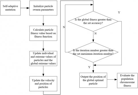
Based on PSO-GA-BPNN, in this paper, the thermal deformation of antenna array surface of vehicle-mounted phased array radar was predicted. This new neural network merged the three optimization methods of PSO, GA, and BPNN. The combination of the three can effectively improve solution accuracy and convergence speed. Based on the global search ability of PSO and GA, the model can adaptively solve the complex and nonlinear problems of thermal deformation, and it can adapt to different geometrical structures, material properties and working conditions, thus it has good versatility and adaptability. The BPNN has a good nonlinear fitting ability and can accurately capture complex physical phenomena such as thermal conduction and thermal expansion. With PSO and GA combined into the model, more accurate predictions of thermal deformation could be made; compared with conventional finite element analysis methods, the neural network-based method can significantly reduce computation time and resource consumption, enabling the model to be more effectively applied to real-time or near real-time prediction scenarios, and thereby satisfying the needs of vehicle-mounted radar systems. Figure 3 gives the flowchart of thermal deformation prediction of antenna array surface of vehicle-mounted phased array radar.
Input parameters of the neural network-based thermal deformation prediction model were set as:
Physical parameters:
1) Material density: the density of the surface material of antenna array, which has a direct effect on thermal deformation; 2) Thermal conductivity: the heat transfer efficiency of the surface material of antenna array; 3) Specific heat capacity: the heat capacity of the material, which is related to temperature change and energy storage; 4) Modulus of elasticity: it describes the deformation ability of the material when subjected to external force; 5) Poisson's ratio: it describes the lateral expansion ability of the material when subjected to compression.
Geometrical parameters:
1) Cross-sectional dimension of micro-channels: such as width and height; 2) Shape of micro-channels: such as rectangular shape, spiral shape, or tree shape; 3) Layout of micro-channels: it describes the distribution of micro-channels on the array surface; 4) Overall structural dimension: such as the total length, width, and thickness of the antenna array surface.
Temperature load parameters:
1) Initial temperature: the initial temperature condition of antenna array surface; 2) Operating temperature: the average temperature or temperature range during the working process; 3) Temperature gradient: the temperature changes of different parts; 4) Heat flow density: such as fixed as 1000kW/m2.
Coordinate parameters:
1) Define the coordinate system: determine the spatial position of the model; 2) Coordinate position of each part: it describes the specific location of each part or unit on the antenna array surface; 3) Start and end coordinates of micro-channels: they describe the geometric positions of micro-channels on the array surface.
The output parameters were set as:
1) The displacement of array units in the X direction; 2) The displacement of array units in the Y direction; 3) The displacement of array units in the Z direction.
Assuming: zu=(zu1,zu2,...,zuf) represents the position of the u-th particle in dimension f, cu=(cu1,cu2,...,cuf) represents the velocity in the f-th dimension, oZYjuf represents the optimal solution of particle u in dimension f during the j-th iteration process, oZYjf represents the global optimal position of the population in the f-th dimension during the j-th iteration, the population size is represented by i=1,2,3,...,M, u=1,2,3,...,L; cjuf represents the f-th dimensional component of the flight velocity vector of particle u during the j-th iteration process, zjuf represents the f-th dimensional component of the position vector of particle u during the j-th iteration process; Q represents the the inertia factor; v1 and v2 represent acceleration constants; v1 represents the individual learning factor; v2 represents the social learning factor; e1 and e1 represent stochastic functions, then the velocity and position update equations of the particles can be written as:
$\begin{aligned} & c_{u f}^{j+1}=\mu c_{u f}^j+v_1 e_1 \times\left(o Z Y_{u f}^j-z_{u f}^j\right) +v_2 e_2 \times\left(o Z Y_{u f}^j-z_{u f}^j\right)\end{aligned}$ (6)
$z_{u f}^j=z_{u f}^{j+1}+c_{u f}^{j-1}$ (7)
Assuming: v1 represents the individual learning factor; v2 represents the social learning factor; e1 and e2 are random numbers conforming to the [0,1] uniform distribution; zhZY represents the position information of the optimal chromosome, y represents the current number of iterations. Then the GA and PSO were combined, and the optimum-searching ability and convergence speed of the algorithm had been improved. The formula below describes the update of individual chromosomes:
$z_u^y=q z_u+v_1 e_1 \cdot\left(z_u-z_k\right)+v_2 e_2 \cdot\left(z_u-z_{h Z Y}\right)$ (8)
In the scenario of thermal deformation prediction of the antenna array surface of vehicle-mounted phased array radar, the constructed PSO-GA-BPNN model can optimize the prediction performance via a self-adaptive crossover design. The crossover operation is one of the core components of GA. By combining the genes of two or more parent individuals to generate new offspring, information exchange and sharing could be achieved. The conventional GA uses a fixed crossover rate, while the design of self-adaptive crossover allows to adjust the crossover rate dynamically. According to the convergence situation and diversity of the population, the system automatically adjusts the frequency and method of crossover operations. Assuming: Ov,MIN represents the lower limit of crossover probability, Ov,MAX represents the upper limit of crossover probability, y represents the number of genetic generations, yMAX represents the maximum number of genetic generations, then the formula for calculating the crossover probability is:
$O_v^y=\left\{\begin{array}{l}\frac{O_{v, M A X}}{2 y}, O_v^y>O_{l, M I N} \\ 1+\frac{y}{y_{M A X}} \\ O_{v, M I N}, O_v^y \leq O_{l, M I N}\end{array}\right.$ (9)
(1) Flow of PSO
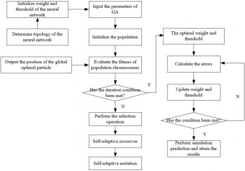
(2) Flow of GA-optimized BPNN
Figure 3. Flow of thermal deformation prediction of the antenna array surface of vehicle-mounted phased array radar
The self-adaptive mutation design is an important part in the PSO-GA-BPNN model as it plays a role in the GA part. The mutation operation of GA introduces new solutions via randomly changing some genes of an individual, thereby increasing the diversity of the population. Unlike the fixed mutation rate of conventional GA, the self-adaptive mutation design dynamically adjusts the mutation rate according to the current state of population. For example, if the diversity of the population decreases, then the mutation rate may be increased to encourage exploration; if the population converges too quickly, then the mutation rate may be decreased to encourage exploitation. The PSO offers global search, the BPNN offers local fine-tuning, and the self-adaptive mutation design ensures the algorithm to keep a balance between global search and local search, avoiding falling into local optimum. Assuming: E represents the Euclidean distance between the fitness values of parents, EMAX represents the maximum Euclidean distance between parent fitness values; ty represents the current number of iterations, yMAX represents the maximum number of iterations, OMAX represents the maximum mutation probability, then the calculation formula of the self-adaptive variation strategy proposed in this paper is:
$O_l=\left\{\begin{array}{l}O_{l, M A X} \cdot\left(1-\frac{y}{y_{M A X}}\right) \cdot\left(1-\frac{O}{O_{M A X}}\right), O_l^y>O_{l, M I N} \\ O_{l, M I N}, O_l^y \leq O_{l, M I N}\end{array}\right.$ (10)
Table 1. Numerical calculation results of heat transfer of different types of heat dissipation micro-channels
|
Type of Micro-Channels |
Standard Deviation |
Maximum Temperature |
Pressure Drop |
|
Parallel |
3.54 |
78.26 |
6.851 |
|
Linear-shaped |
3.12 |
84.15 |
7.638 |
|
Tree-shaped (primary leaf veins) |
3.48 |
77.66 |
6.5219 |
|
Tree-shaped (secondary leaf veins) |
2.89 |
73.26 |
6.8329 |
|
Tree-shaped (tertiary leaf veins) |
2.51 |
73.19 |
7.3268 |
|
Spiral-shaped |
1.23 |
71.58 |
7.1258 |
Table 1 lists the of numerical calculation results of different types of heat dissipation micro-channels on the antenna array surface of vehicle-mounted phased array radar, including the standard deviation, maximum temperature, and pressure drop. Judging from the perspective of heat dissipation uniformity, spiral shaped micro-channels performed the best, while the performance of parallel and linear shaped micro-channels was poor. In terms of the effect of heat dissipation, the spiral shaped micro-channels had the lowest maximum temperature and a good effect of heat dissipation. In terms of pressure drop, the linear shaped micro-channels had greater flow resistance and may need a stronger pumping capacity; the pressure drop of parallel micro-channels was the lowest, and the flow resistance was smaller. In summary, the spiral shaped micro-channels performed excellently in terms of temperature uniformity and heat dissipation, but their pressure drop may need to be weighed. The parallel and linear micro-channels had some disadvantages in some aspects and further design optimization is required to improve their performance. Also, the performance of tree-shaped micro-channels under conditions of different leaf vein levels needs further investigation and optimization.
Table 2. ANOVA results of heat transfer of different types of micro-channels
|
Source of Variance |
Sum of Squares of Deviations |
Degree of Freedom |
Mean Square |
F Value |
Significance |
|
Physical parameters |
0.221 |
3 |
0.078 |
8.238 |
* |
|
Geometrical parameters |
0.215 |
3 |
0.066 |
7.101 |
* |
|
Temperature load parameters |
16.238 |
3 |
5.012 |
531.265 |
** |
|
Coordinate parameters |
0.059 |
6 |
0.011 |
|
|
|
Total |
16.238 |
15 |
|
|
|
Table 2 gives the results of ANOVA analysis of heat transfer through micro-channels on the antenna array surface of vehicle-mounted phased array radar, with four types of influencing factors taken into consideration, namely physical parameters, geometrical parameters, temperature load parameters, and coordinate parameters. As can be seen from the table, the temperature load parameters had the most significant effect on the heat transfer of micro-channels, thus they are the primary influencing factors. Although the physical and geometrical parameters also had a significant effect on heat dissipation, their effects were smaller compared with that of temperature load parameters. As for the coordinate parameters, their influence was insignificant and negligible. These conclusions help to better understand and optimize the design and performance of heat dissipation micro-channels, and the setting of temperature load parameters needs more attention in the design.
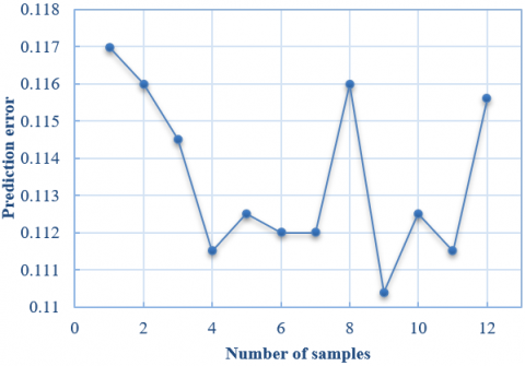
Figure 4. Prediction error of the proposed model on test samples
Table 3 gives the thermal deformation prediction results of test samples of the antenna array surface of vehicle-mounted phased array radar, indicators include the elastic modulus, width×height of micro-channels, temperature gradient, chip coordinates, simulation values, prediction values and errors. As can be seen from the table, in the prediction of all samples and three directions (X, Y, and Z), the range of errors was between 0.7% and 2.1%, indicating that the accuracy of the prediction model was very high. The modulus of elasticity, size of micro-channels, and temperature gradient are key factors affecting the thermal deformation of the antenna array surface. To optimize the design, an in-depth understanding of these parameters is required and they should be well controlled.
Figure 4 gives a curve showing the prediction error of the proposed thermal deformation prediction model on the test samples of antenna array surface of vehicle-mounted phased array radar. The prediction errors of the model on 12 samples ranged from 0.1104 to 0.1170. The error range was small, indicating that the prediction accuracy of the model was relatively high. As can be seen from the figure, there’s no significant systematic error among different samples, suggesting that the model gave a stable prediction performance under different conditions and configurations. The prediction error didn’t exhibit an obvious upward or downward trend as the number of samples increased, proving that the model’s response to different samples was consistent, and not affected by specific sample sequence. These results support the adoption of the proposed model as a tool for predicting and analyzing the thermal deformation of antenna array surface of vehicle-mounted phased array radar. Accurate predictions can contribute to a better understanding and control of these phenomena, thereby improving the performance and reliability of the radar system.
Table 4 lists the displacement of radiation units on antenna array surface under different temperature conditions. The maximum and minimum values in the X, Y and Z directions were given. As can be known from the table, from 40°C to 80°C, the maximum and minimum values in the three directions all increased with the temperature rise, indicating that the temperature rise can lead to an increase in the displacement of radiation units of antenna array. The difference between the maximum and minimum values in each direction also increased with temperature rise, implying that at higher temperatures the distribution of stress and strain in the structure may be more uneven, so it can be concluded that temperature has a significant effect on the displacement of radiation units on antenna array surface, with the temperature rise, the displacement in all three directions would increase accordingly.
Table 3. Thermal deformation prediction results of test samples
|
Sample |
Modulus of Elasticity |
Width×Height of Micro-Channels |
Temperature Gradient |
Chip Coordinates |
Simulation Value (mm) |
Prediction Value (mm) |
Error |
|
1 |
1.0E-5 |
550×180 |
50-60 |
(-0.8,2.2,1.4) |
0.2815(X direction) |
0.2815 |
2.1% |
|
0.2356(Y direction) |
0.2416 |
1.9% |
|||||
|
0.4518(Z direction) |
0.4426 |
1.6% |
|||||
|
2 |
1.0E-5 |
550×180 |
50-60 |
(-0.8,1.2,2.6) |
0.3215(X direction) |
0.3269 |
0.9% |
|
0.3952(Y direction) |
0.3715 |
1.2% |
|||||
|
0.2613(Z direction) |
0.2836 |
1.3% |
|||||
|
3 |
1.0E-5 |
550×100 |
50-60 |
(-0.5,1.9,1.15) |
0.2846(X direction) |
0.2813 |
1.1% |
|
0.7821(Y direction) |
0.8216 |
1.9% |
|||||
|
0.2231(Z direction) |
0.2369 |
0.7% |
|||||
|
4 |
2.5E-5 |
550×180 |
50-70 |
(-0.8,1.25,1.6) |
0.9123(X direction) |
0.8855 |
1.1% |
|
0.2715(Y direction) |
0.2931 |
0.9% |
|||||
|
0.2896(Z direction) |
0.2713 |
1.8% |
Table 4. Displacement of radiation units on the antenna array surface under different thermal environment temperatures
|
Temperature |
Maximum Value in X Direction (mm) |
Minimum Value in X Direction (mm) |
Maximum Value in Y Direction (mm) |
Minimum Value in Y Direction (mm) |
Maximum Value in Z Direction (mm) |
Minimum Value in Z Direction (mm) |
|
40℃ |
0.2215 |
0.1845 |
0.1723 |
0.0075 |
0.2746 |
0.0256 |
|
50℃ |
0.3215 |
0.2478 |
0.2836 |
0.0124 |
0.4219 |
0.0421 |
|
60℃ |
0.4396 |
0.3562 |
0.3519 |
0.0162 |
0.5862 |
0.0523 |
|
70℃ |
0.5412 |
0.4216 |
0.4415 |
0.0185 |
0.7231 |
0.0638 |
|
80℃ |
0.6528 |
0.5238 |
0.5326 |
0.0235 |
0.8516 |
0.0815 |
Table 5. Displacement of array chips under different temperature gradient conditions
|
Temperature Gradient |
Maximum Value in X Direction (mm) |
Minimum Value in X Direction (mm) |
Maximum Value in Y Direction (mm) |
Minimum Value in Y Direction(mm) |
Maximum Value in Z Direction (mm) |
Minimum Value in Z Direction (mm) |
|
30℃~40℃ |
0.2951 |
0.1899 |
0.2715 |
0.0031 |
0.5127 |
0.0312 |
|
30℃~45℃ |
0.4825 |
0.2130 |
0.3216 |
0.0018 |
0.6235 |
0.0362 |
|
30℃~50℃ |
0.5413 |
0.2236 |
0.2715 |
0.0012 |
0.7125 |
0.0378 |
Table 6. Displacement of array chips under conditions of different sizes of micro-channels
|
Width×Height of Micro-Channels |
Maximum Value in X Direction (mm) |
Minimum Value in X Direction (mm) |
Maximum Value in Y Direction (mm) |
Minimum Value in Y Direction(mm) |
Maximum Value in Z Direction (mm) |
Minimum Value in Z Direction (mm) |
|
400mm×80mm |
0.1852 |
0.1236 |
0.1126 |
0.0007 |
0.1745 |
0.0088 |
|
500mm×100mm |
0.1936 |
0.1258 |
0.1185 |
0.0001 |
0.1629 |
0.0095 |
|
550mm×150mm |
0.2631 |
0.1426 |
0.1534 |
0.0031 |
0.2351 |
0.0152 |
|
600mm×180mm |
0.2658 |
0.1458 |
0.1529 |
0.0000 |
0.2388 |
0.0153 |
Table 7. Displacement of array chips under different elastic modulus conditions
|
Chip |
Displacement in X Direction (Condition 1) |
Displacement in X Direction (Condition 2) |
Displacement in Y Direction (Condition 1) |
Displacement in Y Direction (Condition 2) |
Displacement in Z Direction (Condition 1) |
Displacement in Z Direction (Condition 2) |
|
2 |
0.1452 |
0.2785 |
-0.0885 |
-0.1825 |
-0.0152 |
-0.0291 |
|
4 |
0.1533 |
0.2951 |
-0.0695 |
-0.1425 |
-0.0163 |
-0.0312 |
|
6 |
0.1625 |
0.3125 |
-0.0531 |
-0.1122 |
-0.0175 |
-0.0314 |
|
8 |
0.1628 |
0.3266 |
-0.0392 |
-0.0761 |
-0.0185 |
-0.0345 |
|
10 |
0.1788 |
0.3452 |
-0.0251 |
-0.0485 |
-0.0189 |
-0.0369 |
|
12 |
0.1899 |
0.3569 |
-0.0091 |
-0.0186 |
-0.0191 |
-0.0375 |
|
14 |
0.1952 |
0.3695 |
0.0085 |
0.0162 |
-0.0199 |
-0.0384 |
|
16 |
0.1936 |
0.3851 |
0.0285 |
0.0596 |
-0.1876 |
-0.0395 |
|
28 |
0.1899 |
0.3961 |
0.0574 |
0.1238 |
-0.0185 |
-0.0397 |
|
20 |
0.1869 |
0.3845 |
0.0912 |
0.1852 |
-0.0183 |
-0.0381 |
Table 5 gives the data of the displacement of array chips under different temperature gradient conditions. According to the data, it can be clearly seen that as the temperature rose, the maximum displacement in X, Y, and Z directions all increased, indicating that the increase in temperature gradient can increase the thermal strain of array chips. The displacement varied in different directions, which is related to the material properties, structure and force mode of the chips. The minimum value in Z direction was relatively large whereas the minimum value in Y direction was relatively small, implying that the thermal response was different in different directions, and this may be related to factors such as the thermal conduction path and the thermal expansion coefficient. Therefore, for high-precision radar applications, the control and management of temperature gradient is critical for ensuring stable performance under different temperature conditions.
Table 6 gives the detailed data of the displacement of array chips under conditions of different sizes of micro-channels. As can be known from the table, the size of micro-channels can significantly affect the thermal strain of array chips. Specifically speaking, as the width and height increased, the maximum displacement increased accordingly. The minimum displacement in X and Y directions was small, and a detailed analysis is required to determine the underlying physical causes. The minimum displacement in the Z direction increased with the size of micro-channels, suggesting that there are some specific geometric effect or constraints in the design of micro-channels. Figuring out how the size of micro-channels affect the thermal displacement of array chips and using this information to optimize the design can help improve the stability and performance of the radar system.
Based on the data given in Table 7, the displacement of array chips under different elastic modulus conditions could be observed. In the table, Condition 1 is the case with an elastic modulus of 1.16E-5 and Condition 2 is the case with an elastic modulus of 2.5E-5. As can be known from the table, for both conditions, the displacement in the X direction increased as the serial number of chips grew. The modulus of elasticity under Condition 2 was larger, correspondingly, the displacement in X direction was larger as well. Under both conditions, the displacement in Y direction increased from negative values to positive values, which might indicate some kind of bending or twisting phenomenon. The modulus of elasticity under Condition 2 was larger, the absolute value of displacement in Y direction was greater. Under both conditions, the displacement in Z direction was negative, and the value decreased as the serial number of chips grew. Under Condition 2, the displacement was larger. By comparing the two conditions, it is clear that an increase in the modulus of elasticity led to an increase in displacement in all three directions, and this may be related to the relationship between the modulus of elasticity and the stiffness of the material. Therefore, under the two different conditions of modulus of elasticity, the displacement in all three directions was proportional to the modulus of elasticity, and this trend is consistent with the fact that the modulus of elasticity describes the ability of a material to resist deformation.
This study gave an in-depth discussion on the thermal deformation of the antenna array surface of vehicle-mounted phased array radar. Through a series of analyses and experiments, the effects of a few factors, including the modulus of elasticity, temperature gradient, and micro-channel size on the displacement of radiation units were investigated. Based on ANOVA analysis, this paper revealed four types of main influencing factors of thermal deformation, namely physical parameters, geometrical parameters, temperature load parameters and coordinate parameters, among which, the temperature load parameters had the most significant effect, indicating the importance of temperature control to the optimization of thermal deformation. Then, the results of the thermal deformation prediction model were given in the paper, and the prediction accuracy of the proposed model was tested on several test samples. Error analysis showed that the model has good accuracy and reliability, providing a basis for practical applications. After that, the displacement of antenna array under different temperature and temperature gradient conditions was analyzed, and the results showed that an increase in temperature can lead to an increase in displacement, and this conclusion supported the importance of maintaining structural integrity at different temperatures. Moreover, through an analysis on the different sizes of micro-channels, the specific effects of micro-channel size on the displacement of array chips were revealed, and the results could help to fine-tune the radar design to suit specific needs. At last, the array chip displacement under different elastic modulus conditions was analyzed, and it’s found through experiment that the elastic modulus is proportional to displacement, and this conclusion could point out directions for material selection.
In this paper, the thermal deformation of the antenna array surface of vehicle-mounted phased array radar was researched comprehensively, the conclusions revealed the influence of several key factors on the displacement of the array, and a reliable prediction model was proposed. The research findings of this paper provide useful guidance for the optimization of the antenna array surface of vehicle-mounted phased array radar.
This work was supported by Equipment Advance Research Shared Technology Project “Shipborne Lightweight Mechanical Phase-Scanning Multifunctional Radar Technology” (Grant No.: 50913020901).
[1] Chou, H.T., Ho, S.K. (2022). Communication triple-mode planar phased arrays of antennas using trifocal Rotman lens as switchable mode-former for vehicular radar applications. IEEE Transactions on Antennas and Propagation, 70(12): 12340-12345. https://doi.org/10.1109/TAP.2022.3209218
[2] Cho, H., Lee, J.H., Yu, J.W., Ahn, B. (2022). Series-fed coupled split-ring resonator array antenna with wide fan-beam and low sidelobe level for millimeter-wave automotive radar. IEEE Transactions on Vehicular Technology, 72(4): 4805-4814. https://doi.org/10.1109/TVT.2022.3226294
[3] Du, X., Jiang, G., Han, C., Wang, C., Zhou, Y. (2021). DOA estimation based on intelligent FMCW radar with triangle array antenna. Lecture Notes of the Institute for Computer Sciences, Social-Informatics and Telecommunications Engineering (LNICST), 352: 3-16. https://doi.org/10.1007/978-3-030-67720-6_1
[4] Liu, R., Zhang, W., Yu, X., Lu, Q., Wei, W., Kong, L., Cui, G. (2021). Transmit-receive beamforming for distributed phased-MIMO radar system. IEEE Transactions on Vehicular Technology, 71(2): 1439-1453. https://doi.org/10.1109/TVT.2021.3133596
[5] Weedon, W.H. (2022). 5G Ku-band Radar Array for Wide-Area Surveillance. In 2022 IEEE International Symposium on Phased Array Systems & Technology (PAST), Waltham, MA, USA, pp. 1-4. https://doi.org/10.1109/PAST49659.2022.9975002
[6] Schmalenberg, P., Dede, E.M., Nomura, T., Nishiwaki, S. (2022). Optimization of planar phased arrays for vehicles. IEEE Antennas and Wireless Propagation Letters, 21(10): 2140-2144. https://doi.org/10.1109/LAWP.2022.3193655
[7] Wu, Y., Kong, L., Sun, Q., Zhang, J. (2023). Heat transfer path design and heat flow analysis of satellite phased array antenna. Journal of Beijing University of Aeronautics and Astronautics, 49(5): 1127-1134. https://doi.org/10.13700/j.bh.1001-5965.2021.0373
[8] Le Gall, T., Ghiotto, A., Varault, S., Morvan, G., Louis, B., Pillet, G. (2023). Common-mode loss mitigation of a differentially fed eight-port on-antenna power combining patch implemented in a scanning phased array. In 2023 17th European Conference on Antennas and Propagation (EuCAP), Florence, Italy, pp. 1-5. https://doi.org/10.23919/EuCAP57121.2023.10133416
[9] Xu, P., Wang, Y., Xu, X., Wang, L., Wang, Z., Yu, K., Wu, W., Wang, M., Leng, G., Ge, D., Ma, X., Wang, C. (2023). Structural-electromagnetic-thermal coupling technology for active phased array antenna. International Journal of Antennas and Propagation, 2023. https://doi.org/10.1155/2023/2843443
[10] Liu, J., Su, Q., Shi, Z., Xue, X. (2022). Optimization design and performance research on microchannel liquid cooling of phased array antenna. Systems Engineering and Electronics, 44(6): 1782-1788.
[11] Park, J., Choi, D., Hong, W. (2019). Millimeter-wave phased-array antenna-in-package (AiP) using stamped metal process for enhanced heat dissipation. IEEE Antennas and Wireless Propagation Letters, 18(11): 2355-2359. https://doi.org/10.1109/LAWP.2019.2938229
[12] Yang, S., Cheng, W., Wang, L., Zhao, R., Ning, B., Deng, Q. (2022). Thermal design of active phased array antenna for GEO communication satellite based on structure and thermal control integration method. Asia International Symposium on Mechatronics, 885: 1500-1515. https://doi.org/10.1007/978-981-19-1309-9_145
[13] Kitazaki, T., Akaishi, N., Tomiyasu, S., Honma, G. (2021). The new water-cooled cold plate for active phased array antenna using AM technology. In 2021 IEEE Radar Conference (RadarConf21), Atlanta, GA, USA, pp. 1-5. https://doi.org/10.1109/RadarConf2147009.2021.9455254
[14] Qian, S., Lou, S., Wang, W., Yu, M. (2023). Multidisciplinary topology optimization design of cold plate for active phased antenna array. Structural and Multidisciplinary Optimization, 66(7): 2223-2232. https://doi.org/10.1007/s00158-023-03618-5
[15] Bagheri, A., Bencivenni, C., Gustafsson, M., Glazunov, A.A. (2023). A 28 GHz 8×8 Gapwaveguide phased array employing GaN front-end with 60 dBm EIRP. IEEE Transactions on Antennas and Propagation, 71(5): 4510-4515. https://doi.org/10.1109/TAP.2023.3240837
[16] Kedar, A., Bisht, A.S., Sreenivasulu, K., Rao, D.S., Vishwakarma, N.K. (2020). GaN based wide band C-band active phased array antenna design with wide scan volume. In 2020 IEEE International Radar Conference (RADAR), Washington, DC, USA, pp. 88-93. https://doi.org/10.1109/RADAR42522.2020.9114841
[17] Chu, W., Lyu, Y., Wang, Y., Wang, Q. (2022). Development of thermal management technologies for spaceborne active phased array antennas. Journal of Huazhong University of Science and Technology (Natural Science Edition), 50(12): 106-120.
[18] He, J., Wang, Y., Meng, T., Wang, Q., Chu, W. (2022). Experimental study on heat dissipation characteristics of flat heat pipe with temperature-controlled phase change material applied to high-power T/R module. Journal of Xi'an Jiaotong University, 56(6): 142-150.
[19] Cong, B., Kong, Y., Ye, Y., Liu, R., Du, X., Yu, L., Jia, S., Qu, Z., Jiao, B. (2023). A combined solution of thermoelectric coolers and microchannels for multi-chip heat dissipation with precise temperature uniformity control. Applied Thermal Engineering, 219: 119370. https://doi.org/10.1016/j.applthermaleng.2022.119370
[20] Aziz, I., Wu, D., Öjefors, E., Hanning, J., Dancila, D. (2022). 28 GHz compact dipole antenna array integrated in fan-out eWLB package. International Journal of Microwave and Wireless Technologies, 14(10): 1369-1377. https://doi.org/10.1017/S1759078722000058
[21] Qian, S., Wang, W., Ge, C., Lou, S., Miao, E., Tang, B. (2018). Topology optimization of fluid flow channel in cold plate for active phased array antenna. Structural and Multidisciplinary Optimization, 57(6): 2223-2232. https://doi.org/10.1007/s00158-017-1852-8