Ali Sabri Abbas![]() | Ayad Ali Mohammed*
| Ayad Ali Mohammed*![]()
© 2023 IIETA. This article is published by IIETA and is licensed under the CC BY 4.0 license (http://creativecommons.org/licenses/by/4.0/).
OPEN ACCESS
Several measures have been explored to improve the function of plate-fin heat exchangers (PFHEs), including improving heat transfer surface, heat transfer coefficient, finned surface thermal efficiency, and vortex generators. We employ computational approaches in this article to investigate the flow and heat transmission parameters of a plate-fin heat exchanger (PFHE) with a longitudinal vortex generator (LVG) installed on an offset rectangular-triangular fin (ORT), as proposed in a previous work. In order to improve convective heat transmission while reducing pressure loss, the research used a rectangle wing pair (RWP) LVG installed on the fin. Using the ANSYS FLUENT is used to get the numerical outcomes. The top and lower plates are subjected to constant heat flux, and the working fluid (air) is chosen to be laminar (600 Reynolds 1400). The energy conservation problem was solved using the finite volume and finite difference (FD) approaches. Wing angles of approach (25, 35, 45, and 55°) and RWP LVG height were changed to assess the LVG's effectiveness. When compared to the reference instance, the Nusselt number rises by 22.23% when a CFU integrated RWP LVG is used at an angle of approach and height of (45°, 1.25mm). Contour and streamline maps were used to illustrate the temperature distribution of both primary and secondary flows.
plate fin heat exchanger, plain fins, offset strip fins, vortex generator, rectangular winglet pair, performance, enhancement
Presence of VGs results into improves fluid mixing and raises the efficiency of heat transfer then causes high exchange of heat between the wall and the fluid [1].
Using VGs to disrupt the formation of the thermal boundary layer while concurrently disrupting the hydrodynamic boundary layer can improve the gas side coefficient of heat transfer. Shape, position, geometry, and assault angle are all factors that can affect VG performance [2].
Heat transmission improvement using various VGs has been the subject of a great deal of practical and computational research.
Ganesh et al. [3] conducted numerical studies on the possibility of PFHE to enhance Heat Transmission on Improved Fin Surfaces. Using the Fluent ANSYS program, a steady-state energy formula and a three-dimensional Navier-Stokes formula have been calculated.
The resulting geometry was a PR with a DWP VG placed into it. In order to set up the CFD analysis, four different attack angles (15°, 25°, 35°, and 45°) and a range of Re-numbers (I1000 to I4000) were examined. Based on the results obtained for the various (β) values of the IVGs, The DWPIVG achieved most effectively in terms of heat transfer at a 25° attack angle across all Re-number levels.
Gupta et al. [4] investigated laminar convection heat transport in a PFHE with triangular fins and VG numerically. For "Marker and Cell" method employs an asymmetrical grid approach to answer both the full energy equation and the Navier-Stokes equation. An RWVG is attached to the triangular fins. The findings showed that when the attack angle was increased, the average Nu-number increased. In addition, when the Re-number was increased, the length of the LVG increased. Heat transmission increases with a moderate pressure reduction rise in heat transport.
The researchers calculated the performance metrics connected with the improvement of heat transfer employing WVGs in the laminar flow regime in the study done by Ebrahimi and Kheradmand [5]. They used Fluent software to calculate using a steady three-dimensional Navier-Stokes formula and an energy formula. The study focused on two delta winglets (DWP) and two rectangle winglets (RWP). The results showed that using LVGs enhanced the heat transfer of the heat exchanger (IHE). When the non-dimensional specified parameter for performance estimate (Nu m/NuIm,0)/(f/f0) was evaluated, it was discovered that the channel with DWP outperformed RWP in terms of overall performance. Specifically, The CFD configuration of DWP fared better at Re-numbers less thanI720, whereas the CFU arrangement of DWP performed better at Re-numbers greater than 720. Similarly, in terms of total performance, the CFD arrangement outperformed the CFU configuration for RWP.
Khoshvaght-Aliabadi [6] examined the influence of vortex generators and Cu/water nanofluid movement on the efficiency of plate-fin heat exchangers experimentally. The assessment findings show that utilizing the VG channel instead of the regular channel increases the heat-transfer rate. Furthermore, the effectiveness of VG channel PFHE was shown to be superior to that of Nanofluid. As a result, in both VG and PEG, we see a marked improvement in the temperature-gradient heat transmission (h) compared to the usual two techniques. By correlating and h, we can infer the global Nusselt number (Nu) or Sherwood number (Sh). The document allows for drawing conclusions.
In the research conducted by Vasudevan et al. [7], a statistical study was performed using the "Marker and Cell" technique on a grid that is staggered to investigate the potential improvement of triangular fins with attached DWP on their inclined surfaces. The results demonstrated that it is possible to achieve a 20-25% increase in heat transmission with only a minor pressure loss. Furthermore, the position of the DWVG during the flow significantly impacts the heat amplification it generates. Triangular fins with associated DWVGs, also known as secondary fins, offer Shows great potential as inserts in a PFHE's flow passages formed by two neighboring plates, according to the research. Furthermore, the DWVGs may be punched out to facilitate manufacture, with stampings made on the duct wall. Heat transfer is substantially improved despite the fact that the flow structure becomes more complex.
Sachdeva et al. [8] examined heat-transfer enhancement in a PFHE by combining triangular fins and a RWVG on its inclined surface in their experimental investigation. The Navier-Stokes and continuity equations were solved using the "Marker and Cell" approach. When compared to a PFHE without any VGs, using a RWVG at a 26°Iangle of attack resulted in a significant 35% improvement in the overall longitudinally averaged Nu-number.
Additionally, Sachdeva et al. [9] conducted research to better understand the flow in plate-fin triangle channels by examining the performance of delta wing vortex generators. They also analyzed the efficiency of pumping power, This was discovered to rise with increasing (β) but decrease with increasing Re-number. While the stamped DWVG was less successful than the linked one, it had the advantage of being easier to produce.
In their numerical analysis, Gupta and Kasana [10] investigated the effect of installing LVGs in-line with the duct on heat transmission in a PFHE. The simulations demonstrated a significant improvement in heat transfer with the presence of LVGs. Furthermore, the heat transfer further increased as the Re number increased.
The main objectives of this study are twofold. Firstly, to investigate the impact of vortex generators on heat transfer in a single-phase fluid within a PFHE. Secondly, to enhance our understanding of the heat transfer mechanism occurring when a fluid flows through the ORT fin with the aid of a vortex generator configuration, with a specific focus on the rectangular winglet pair vortex generator integrated into the fin surfaces.
Additionally, the performance of the PFHE will be examined for different attack angles and heights of the rectangular winglet pair at various Re-numbers. This analysis aims to provide a comprehensive evaluation of the PFHE's performance under different operating conditions, shedding light on the optimal configuration for enhanced heat transfer.
A novel concept known as ORT (Rectangular Winglet Pair on Common Flow Down) proposed by Abbas and Mohammed [11] was investigated in this study. Figure 1 illustrates the ORT configuration which was proposed by Abbas and Mohammed [11], which consists of a rectangular winglet pair (RWP) mounted on a common flow down (CFD) shape. Figure 2 provides a brief overview of the ORT configuration. The RWP is inclined at different angles of attack (β) with respect to the flow direction, specifically 25°, 35°, 45°, and 55°. The leading edges of the RWP are positioned at three different heights (h=0.75 mm, 1 mm, andI1.25 mm).
To analyze the heat transfer performance, plate-fin heat exchanger (PFHE) geometries with embedded LVGs were constructed using Workbench 2021. Figures 1 and 2 depict the front aspect of the computing domain for each example.
Air with varying laminar Re numbers (velocities) is admitted to the PFHE and exits at a predetermined point called the discharge limit. The flow field will be solved under conditions of linearity, isothermally, and steady state. The study included five Re values, fromI600 toI1400, and one Pr value. Knowing the local heat flow, which is 3000 w/m, and the values of the local heat-transfer coefficients along the top and lower plates made the computation possible.
Figure 1. (a) OSF rectangular-triangular fin, (b) Front view of a OSF rectangular-triangular fin [11]
Figure 2. a- Fin with an LVG and a trapezoidal triangle on an OSF b- The LVG-equipped rectangular-triangular tail of an OSF, seen from the front
3.1 Presumptions
The following simplifications are made to the model answer proposed:
3.2 Governing calculations
The continuity, momentum, and energy equations regulate laminar fluid flow motion and heat transfer. The equations take the following form:
3.2.1 Continuity equation
The continuity equation serves as a quantitative representation of mass conservation. Its shape is [12]:
$\frac{\partial U}{\partial x}+\frac{\partial V}{\partial y}+\frac{\partial W}{\partial z}=0$ (1)
$\frac{\partial u}{\partial x}+\frac{\partial v}{\partial y}+\frac{\partial w}{\partial z}=0$ (2)
3.2.2 Momentum equations (INSEs)
The formulae of momentum were developed using Newton's second rule of momentum to account for the conservation of fluid momentum in the x, y, and z dimensions of fluid motion [13]. The Navier and Stokes equations (NSE) are the term given to these equations [14]:
Momentum equation in x-direction:
$\rho\left(u \frac{\partial u}{\partial x}+v \frac{\partial u}{\partial y}+w \frac{\partial u}{\partial z}\right)=-\frac{\partial p}{\partial x}+\left(\frac{\partial^2 u}{\partial x^2}\right)+\left(\frac{\partial^2 u}{\partial y^2}\right)+\left(\frac{\partial^2 u}{\partial z^2}\right)$ (3)
Momentum equation in y-direction:
$\rho\left(u \frac{\partial v}{\partial x}+v \frac{\partial v}{\partial y}+w \frac{\partial v}{\partial z}\right)=-\frac{\partial p}{\partial x}+\left(\frac{\partial^2 v}{\partial x^2}\right)+\left(\frac{\partial^2 v}{\partial y^2}\right)+\left(\frac{\partial^2 v}{\partial z^2}\right)$ (4)
Momentum equation in z-direction:
$\rho\left(u \frac{\partial w}{\partial x}+v \frac{\partial w}{\partial y}+w \frac{\partial w}{\partial z}\right)=-\frac{\partial p}{\partial x}+\left(\frac{\partial^2 w}{\partial x^2}\right)+\left(\frac{\partial^2 w}{\partial y^2}\right)+\left(\frac{\partial^2 w}{\partial z^2}\right)$ (5)
3.2.3 Energy equation
$u \frac{\partial T}{\partial x}+v \frac{\partial T}{\partial y}+w \frac{\partial T}{\partial z}=\frac{k}{\rho C_p}\left[\frac{\partial^2 T}{\partial x^2}+\frac{\partial^2 T}{\partial y^2}+\frac{\partial^2 T}{\partial z^2}\right]$ (6)
3.3 Boundary conditions
3.4 Hydrodynamic parameters
In this section, some physical definitions which manage the primitive variables of non-Newtonian fluids flow and heat transfer through the PFHE such as velocity, pressure and temperature fields are given. These definitions may conclude local and average characteristics like skin friction coefficient, Nusselt number, Colburn factor, etc., as shown in Table 1.
3.5 Grid independency
In order to choose the optimal grid and improve the answer, a mesh independence study is created. For the purpose of this study into grid independence, seven distinct f-factor numbers were considered. Table 2 summarizes the Re=600 grid requirements for the investigated forms. Based on the results of the grid resolution study, the grid independence of ORT without VG occurs at cell 186213, and that of ORT with VG occurs at cell 745032.
Table 1. The physical definitions which manage the primitive variables of non-Newtonian fluids flow and heat transfer through the PFHE
|
Parameters |
Equation |
Equation Number |
|
Pressure Drop |
Pin-Pout=ΔP |
7 |
|
Reynolds Number [15] |
$\operatorname{Re}=\rho \ U_{i n} D_h / \mu$ |
8 |
|
Hydraulic Diameter [16] |
$D_h=\frac{4 A_c}{P_{e r}}=\frac{4 A_c L}{A}$ |
9 |
|
Nusselt Number [17] |
$\mathrm{Nu}=\frac{1}{A_{(x, z)}} \int_0^l \int_0^w N u \ d z d x$ $N u=\frac{h \ D_h}{k}$ |
10 11 |
|
Friction Coefficient |
$\mathrm{C}_{\mathrm{f}}=\tau_{\mathrm{w}} / \frac{1}{2} \rho \mathrm{U}^2$ |
12 |
|
Wall is Shear Stress |
$\tau_{\mathrm{w}}=\mu \sqrt{\left(\frac{\partial \mathrm{u}}{\partial \mathrm{y}}\right)^2+\left(\frac{\partial \mathrm{w}}{\partial \mathrm{y}}\right)^2}$ |
13 |
|
Fanning Fraction Factor |
$c_f=\frac{f}{4}$ |
14 |
|
Colburn (j) Factor [18] |
$\mathrm{j}=\mathbf{S t} \operatorname{Pr}^{2 / 3}=\frac{\mathrm{h}}{\rho {u} \mathrm{C}_{\mathrm{p}}} \operatorname{Pr}^{2 / 3}$ |
15 |
Table 2. Grids containing f-factor findings from various studies
|
No. |
Case |
No. of Grid Elements |
f |
fdeviation |
|
1 |
ORTT |
65012 |
0.119822731 |
0.058251 |
|
82986 |
0.112842995 |
0.072626 |
||
|
113658 |
0.10464768 |
0.020731 |
||
|
186213 |
0.10247824 |
0.094378 |
||
|
292682 |
0.0928065 |
0.133911 |
||
|
622526 |
0.0803787 |
0.151254 |
||
|
1211330 |
0.0682211 |
|
||
|
2 |
ORT with RWP of (h=1.25mm and β=45o) |
255125 |
0.212 |
0.037736 |
|
498210 |
0.204 |
0.027451 |
||
|
622001 |
0.1984 |
0.008562 |
||
|
745032 |
0.196701 |
0.0117 |
||
|
850848 |
0.1944 |
0.010288 |
||
|
932555 |
0.1924 |
0.010395 |
||
|
1120025 |
0.1904 |
|
3.6 Solving by FLUENT
One of the commercial computational fluid dynamics (CFD) codes is used to perform the exact analysis of the governing equations and boundary conditions that were previously explained. The momentum and energy equations are discretized inside the computational domain using a finite volume technique, and ANSYS Fluent 2021 R1 software is created in this article to analytically study the stated issue [19]. Laminar modeling and finite volume discretization are used to estimate the governing equations. A double accuracy pressure-based solver is used for the numerical calculation. The discretization of all terms for pressure velocity coupling was carried out using the SIMPLE technique and a second-order upwind strategy. A non-slip border condition is added to the PFHE surface.
3.7 Validations
This paper establishes analytically the OSF fin's J-factor. values in the PFHE., based on the practical studies of Yang et al. [20]. In Figure 3 we see the results of these J-factor-counting validations. The present mathematical work deviates from the tests carried out in study [20] by an overall mean of only 3% for the J-factor, demonstrating good alignment.
Figure 3. The J-factor was derived numerically and compared to actual data from Yang et al.'s air experiments [20]
In this subsection, the analytical findings used to validate the enhancement of obligatory convection.in a PFHE the OSF fin's J-factor values in the PFHE with the OSF fin's J-factor values in the PFHE ORT fin. shapes and. the assistance of a vortex. generator. are reviewed and addressed. The hydraulic dimension of the fins region for the ORT without the RWP VG is (0.00308m) and for the RWP VG-equipped version, it is (0.013m) (0.00444m).
4.1 PFHE performance analysis using the longitudinal vortex generator
4.1.1 Variation. of the angle of attack and the height of the LVG
Nusselt number. The effect of varying the angle of attack and the height of the RWP on the average Nusselt number variation for laminar Reynold number Re=600 and entrance length of VG (L=0.5mm) is described in Figure 4.
The findings are obtained by varying the winglet's attack angle=25, 35, 45, and 55o. It is noted that raising the angle of attack increases the Nu-number of the ORT fin, because the VG presents more impediments to the flow and thus increases the intensity of the vortices, which leads to more mixing of the fluid and thus increases the rate of heat transfer. When the vortices are stronger, there is more mixing among the heated fluid near the top and the chilly fluid in the center, resulting in a greater temperature gradient, which raises the value of Nuav. The figure show that the VG with an attack angle of 45° brings about the highest increase in the Nu-number and the coefficient of heat transfer which is agreed with [15]. Also it can be shown that by increasing the attack angle more than 45°, the VG has a weaker performance that creates vortexes vanish faster away from the VG location, which reduces the coefficient of heat transfer and the Nu-number.
When performing the computations, the height of the RWP is varied between (h=0.75, 1 and 1.25 mm) while the length is held fixed at Lw=3 mm. The image illustrates the increase in Nu-number as the RWP height is increased, as a result of an increase in velocity at the side border of the VG for a fixed volume flow rate. As a consequence, the fluid mixes more because of the increased strength of the swirls, and the mass temperature and heat transfer increase [14]. When the Re-number, attack angle, and height of the LVG are set to 600, 45o, and 1.25mm respectively, the findings indicate that the optimal increase in the mean Nu number is found to be 14.85% for an ORT fin with a RWP of entry length equivalent to (L=0.5mm).
Figure 4. Effect of angle of attack and VG height on Nusselt number at entrance length L=0.5mm and Re=600
Figure 5. Effect of angle of attack and VG height on pressure drop at entrance length L=0.5mm and Re=600
Pressure loss. Pressure loss due to the obstruction in the flow rises with the angle of approach. Figure 5 depicts the effect of changing the angle of attack and RWP height on the pressure drop variance for a laminar Reynold number of Re=600. By changing the angle of approach of the winglet VG pair from=25°, 35°, 45°, and 55°, the computations can be completed. It has been observed that raising the ORT fin's angle of approach while using RWP raises the pressure decrease. Therefore, the pressure loss and heat transmission can be improved by raising the attack angle of the VG from 0 to 45 degrees. Unfortunately, increasing the attack angle from 45 degrees to 90 degrees raised the undesirable pressure loss.
To complete the math, we adjust the winglet VG pair's height to h=0.75, 1, and 1.25 millimeters while holding the length constant at Lw=3 mm. Since increasing the height of the VG decreases the fluid path area, raising the RWP results in a greater pressure decline [15]. This is depicted graphically in the figure. The results showed that the smallest Reynolds number, angle of attack, and height of the LVG equal to (=600), (=45o), and (h=1.25mm), respectively, resulted in the lowest pressure drop, while the optimum Nu enhancement cases showed a pressure drop of (=48.95%) for an ORT fin with an entrance length of 0.5mm.
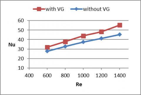
4.1.2 The influence of the Reynold number on the LVG
Nusselt number. Figure 6 depicts the average Nusselt number change as a function of changing the LVG's Reynold number at the optimal angle of attack and height (=45o, h=1.25mm).
Figure 6. Effect of Reynold number with the LVG of (β=45o, h=1.25mm) on the Nusselt number
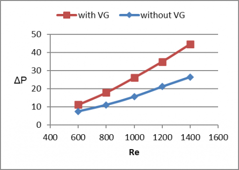
Figure 7. The pressure drop is affected by the Reynold number with the LVG of (=45o, h=1.25mm)
Laminar Reynolds numbers of 600, 800, 1000, 1200, and 1400 were used in the calculations, demonstrating an increase in heat transfer efficiency as a function of Reynolds number. This is because, as the bulk movement rate increases with increasing Reynolds number, so does the rate at which heat is removed. Thicker temperature boundary layers and less fluid contact are associated with higher Reynolds numbers. Therefore, with an increase in Reynolds number, heat transmission improves [14]. The findings indicate that the Nusselt number can be improved upon by 22.23% more with the RWLVG compared to the ORT fin when the Reynold number is 1400.
Pressure loss. As the Reynolds number rises, so do the inertia forces, causing the pressure drop to rise. Figure 7 shows how adjusting the Reynolds number of the LVG affects the average pressure loss variation at the ideal angle of attack and height (=45°, h=1.25mm). Laminar Reynolds values of 600, 800, 1000, 1200, and 1400 were used in the calculations. The pressure loss peaked at Re=1400, representing a 44.69% increase over the RWP LVG configuration, outperforming the ORT fin without the use of LVGs.
4.1.3 Thermal properties of PFHE using a longitudinal vortex generator
The temperature range encountered by the domain of ORT fin in a PFHE employing the LVG of (=45o, h=1.25mm, L=0.5mm, and Re=600) is discussed in this section. We were able to appropriately record a temperature curve for the ORT fin without and with RWP VG, as illustrated in Figures 8 and 9. The domain section is depicted in frames b, c, and d at L=4mm, L=8mm, and L=12mm, respectively. to the level where the downward trend causes the domain's output temperature to rise. Temperature distribution plots demonstrate that the redesigned ORT fin design, to which the vortex generators are attached, minimizes the interior cold zone in the fluid domain, The dark blue flowing hue entering the domain represents this. The blue region is decreased, and heat transfer among the fins and the flowing fluid is improved, as shown in the images below. The longitudinal vortices allow fluid along the walls to exchange with fluid in the middle [21], disrupting the boundary layer. It raises the temperature gradient at the surface, increasing heat transmission.
Figure 8. ORT fin temperature profile at Re=600. Domain a, fluid in touch with the tail; Domain b, at l=4mm; Domain c, at l=8mm; Domain d, at l=12mm [1]
Figure 9. Using the LVG parameters (=45o, h=1.25mm, L=0.5mm) for Re=600, we can see the temperature spread across the ORT fin. flowing domain touching the tail (a), L=4mm domain section (b), L=8mm domain section (c), and L=12mm domain section (d)
Figure 10. Stream lines for ORT fin. a- without LVG b- with aid of the LVG
Figure 11. Stream lines for ORT fin. a- L=0mmIb- L=2mm c- L=3mm d- L=4mm e- L=8mm f- L=12mm
4.1.4 Streamline
Figure 10 displays the streamline patterns in a PFHE with air flowing at Re=600 for the ORT fin design and the ORT setup with the LVG. Figure 11 shows frames a, b, c, d, e, and f, which depict the flow behavior and properties within the PFHE leading to the enhancement of heat transfer. The streamline visualization clearly demonstrates the impact of the LVG on the flow behavior, promoting better heat transfer performance in the ORT configuration.
The aim of this article is to improve heat transfer in PFHE using the (ORT) fin proposed in study [1] by mounting a RWP type longitudinal VG to its surface and developing a computational thermodynamic fluid model capable of forecasting flow and heat transfer parameters at laminar Re-numbering. Computational research has been conducted to ascertain flow and heat transmission parameters for varied attack angles (β) and RWP heights. The computationally calculated j-factor correlates well with the real data from Yang et al. [20].
5.1 Conclusions
1- The Common flow up (ICFU) setup with RWPILVG at attack angle and height (=45o, h=1.25mm) provides a maximal heat transmission rate compared to the basic case configuration.
2- The PFHE's heat transmission is improved with the help of the RWP. It is discovered that the thermal boost value rises up to an angle of approach of 45 degrees, whereafter it marginally falls. For RWP angles=25°, 35°, 45°, and 55° at a height of (h=1.25mm) in the Reynolds Re=600, the Nusselt number rises to 31.05, 31.57, 31.93, and 31.32,Irespectively, in comparison with the basic case Nusselt number of 27.8.
3- The use of LVGs increases the pressure drop in the PFHE flow, The results of the simulation indicate that the pressure drop increases to 8.99, 10.06, 11.26 and 12.42 as compared with base case pressure drop 7.56, respectively for RWP angles β (=25°, 35°, 45° and 55°) with height of (h=1.25mm) in the Reynolds Re=600.
4- Higher Re numbers allow for more efficient heat dissipation because of the greater mass movement rate. As the Re-number rises, heat transmission consequently improves. The findings indicate that for Re=1400, the Nu-number achieves its maximum enhancement values by using a RWLVG that is 22.23% higher than the ORT fin.
5- Since the RWP results in a more compact heat exchanger, the heat transmission rate improves, but the circulating power also rises. To improve heat transmission by 14.85-22.23%, a pressure decrease of 48.94-68.46% is required.
6- Increasing the height of the VGs improves heat transfer at all angles of attack and entrance lengths.
7- For every Common flow up CFU setup, the proportion of heat transfer improvement relative to the basic case design grows with rises in attack angle, height, and Reynolds number.
5.2 Future work
Future work could include experimentally investigating the thermal and hydrodynamic fields of the current study, and compare the numerical and experimental results. Also an inspection of turbulent region using different turbulent models could be achieved in the future works.
|
ORT |
offset rectangular-triangular |
|
RWP |
rectangular winglet pair |
|
L |
entrance length |
|
β |
angle of attack |
|
A |
Heat transfer area |
|
Ac |
Cross-sectional area |
|
Dh |
Hydraulic diameter |
|
HE |
Heat exchanger |
|
PFHE |
Plate-fin heat exchanger |
|
OSF |
Offset strip fins |
|
LVG |
Longitudinal Vortex generator |
|
CFU |
common flow up |
|
h |
height |
|
f |
Fanning friction-factor |
|
h |
Heat transfer coefficient |
|
j |
Colburn-factor |
|
l |
Fin length |
|
P |
Perimeter |
|
Pr |
Prandtl number |
|
Q |
Heat transfer rate |
|
Re |
Reynolds number |
|
St |
Stanton number |
|
S |
Fin spacing |
|
t |
Fin thickness |
|
v |
Flow velocity |
[1] Samadifar, M., Toghraie, D. (2018). Numerical simulation of heat transfer enhancement in a plate-fin heat exchanger using a new type of vortex generators. Applied Thermal Engineering, 133: 671-681. https://doi.org/10.1016/j.applthermaleng.2018.01.062
[2] Brockmeier, U., Guentermann, T.H., Fiebig, M. (1993). Performance evaluation of a vortex generator heat transfer surface and comparison with different high performance surfaces. International Journal of Heat and Mass Transfer, 36(10): 2575-2587. https://doi.org/10.1016/S0017-9310(05)80195-4
[3] Ganesh, N., Theertham, H.K., Senthilkumar, S. (2018). Heat transfer augmentation of compact plate fin heat exchanger using modified fin surfaces (No. 2018-28-0012). SAE Technical Paper. https://doi.org/10.4271/2018-28-0012
[4] Gupta, M., Kasana, K.S., Vasudevan, R. (2010). Heat transfer augmentation in a plate-fin heat exchanger using a rectangular winglet. Heat Transfer-Asian Research, 39(8): 590-610. https://doi.org/10.1002/htj.20318
[5] Ebrahimi, A., Kheradmand, S. (2012). Numerical simulation of performance augmentation in a plate fin heat exchanger using winglet type vortex generators. International Journal of Mechanical Engineering and Mechatronics, 1(2): 109-121. https://doi.org/10.11159/ijmem.2012.014
[6] Khoshvaght-Aliabadi, M. (2016). Thermal performance of plate-fin heat exchanger using passive techniques: vortex-generator and nanofluid. Heat and Mass Transfer, 52(4): 819-828. https://doi.org/10.1007/s00231-015-1603-6
[7] Vasudevan, R., Eswaran, V., Biswas, G. (2000). Winglet-type vortex generators for plate-fin heat exchangers using triangular fins. Numerical Heat Transfer, Part A: Applications, 38(5): 533-555. https://doi.org/10.1080/104077800750020423
[8] Sachdeva, G., Kasana, K.S., Vasudevan, R. (2010). Heat transfer enhancement by using a rectangular wing vortex generator on the triangular shaped fins of a plate‐fin heat exchanger. Heat Transfer—Asian Research: Co‐sponsored by the Society of Chemical Engineers of Japan and the Heat Transfer Division of ASME, 39(3): 151-165. https://doi.org/10.1002/htj.20285
[9] Sachdeva, G., Vasudevan, R., Kasana, K.S. (2010). Computation of heat transfer enhancement in a plate‐fin heat exchanger with triangular inserts and delta wing vortex generator. International Journal for Numerical Methods in Fluids, 63(9): 1031-1047. https://doi.org/10.1002/fld.2113
[10] Gupta, M., Kasana, K.S. (2012). Numerical study of heat transfer enhancement and fluid flow with inline common‐flow‐down vortex generators in a plate‐fin heat exchanger. Heat Transfer—Asian Research, 41(3): 272-288. https://doi.org/10.1002/htj.20414
[11] Abbas, A.S., Mohammed, A.A. (2022). Augmentation of plate-fin heat exchanger performance with support of various types of fin configurations. Mathematical Modelling of Engineering Problems, 9(5): 1406-1414. https://doi.org/10.18280/mmep.090532
[12] Mahdi, H. (2004). Numerical and experimental study of enhancement of heat transfer in roughened ribbed duct. PHD thesis, Department of technical Eduction, University of technology, Iraq.
[13] Versteege, H., Malasekera, W. (1995). An Introduction to Computational Dynamics. Prentice Hall.
[14] Saysroy, A., Eiamsaard, S. (2017). Enhancing convective heat transfer in laminar and turbulent flow regions using multi - channel twisted tape inserts. International Journal of Thermal Sciences, 121: 55-74. https://doi.org/10.1016/j.ijthermalsci.2017.07.002
[15] Nabil, R., Sabri, A. (2022). A review on the modification of circular fin and tube heat exchangers through new innovative fin shapes. International Journal of Advanced Technology and Engineering Exploration, 9(93):1122-1245. https://doi.org/10.19101/IJATEE.2021.875888
[16] Abbas, N.Y., Mustafa, A.W., Askera, M.K.A.A. (2021). Constructal design of heat exchangers: A review. International Journal of Advances in Engineering and Management, 3(12): 27-40. https://doi.org/10.35629/5252-03122740
[17] Abbas, A.S., Mohammed, A.A. (2022). Enhancement of plate-fin heat exchanger performance with aid of various types of fin configurations: A review. Journal of Advanced Research in Fluid Mechanics and Thermal Sciences, 99(2): 48-66. https://doi.org/10.37934/arfmts.99.2.4866
[18] Ali, I.M., Mussa, M.A., Mustafa, M.M. (2017). Experimental investigation of forced convection heat transfer in open cell copper fins. Al-Nahrain Journal for Engineering Sciences, 20(1): 272-280.
[19] Fluent, A. (2021). ANSYS Fluent 2021 R1 user’s guide and theory manual. Ansys Fluent Inc.
[20] Yang, H., Wen, J., Wang, S., Li, Y. (2018). Effect of fin types and Prandtl number on performance of plate-fin heat exchanger: Experimental and numerical assessment. Applied Thermal Engineering, 144: 726-735. https://doi.org/10.1016/j.applthermaleng.2018.08.063
[21] Abbas, A.S., Mohammed, A.A. (2023). Improvement of plate-fin heat exchanger performance with assistance of various types of vortex generator. CFD Letters, 15(7): 131-147. https://doi.org/10.37934/cfdl.15.7.131147