Zhi Li![]() | Yu Wang
| Yu Wang![]() | Weichen Wang
| Weichen Wang![]() | Lin Ruan*
| Lin Ruan*![]()
© 2023 IIETA. This article is published by IIETA and is licensed under the CC BY 4.0 license (http://creativecommons.org/licenses/by/4.0/).
OPEN ACCESS
The self-circulating evaporative cooling system, utilizing latent heat, can meet the cooling requirements of high-power electronics. However, the conventional structure of ribbed columns is not effective for gas-phase fluid discharge and timely liquid-phase fluid feedback, thereby hindering the improvement of heat dissipation. Therefore, a hybrid rib array structure heat exchanger is proposed with advantages of efficient separation of bubbles. This structure consists of a significant number of parallelogram section columns, constructed by a further oblique milling step with 30°, 45° or 60° bevel angles relative to the main flow direction, based on traditional ribbed columns. This study aims to investigate the effect of rib height, rib width, spacing, and angle on the heat transfer performance of hybrid rib array heat exchangers. The experimental data shows that the 30° hybrid rib structure reduces temperatures by 9.3℃ compared to the traditional structure under 100 kW/m2. Moreover, the 30° angle significantly enhances the heat transfer performance compared to the other angles tested. The heat transfer performance of traditional structures improves when using 1:3 width-to-height ratio in the rib section. In contrast, the heat transfer performance of hybrid rib arrays is influenced by the rib height in conjunction with rib width and spacing.
hybrid rib array, enhancing heat transfer performance, angle, height
Considerable research attention has turned to the development of efficient cooling mechanisms for high power electronics, especially since the power rise of DC transmission. It is often necessary to maintain a specific temperature of the components in these devices under conditions of thermal flux density of 50, 100, 150 kW/m2, or even higher. One promising approach is evaporative cooling, which provides high heat transfer coefficients and temperature homogenization, making it ideally suited for high heat flux electrical heat sources. The liquid box, which serves as the central cooling component, plays a crucial role in determining the heat transfer efficiency. Although various intricate mechanisms enhance heat transfer efficiency, these methods inevitably elevate the flow resistance of the heat transfer fluid (HTF). The self-circulating system primarily depends on the liquid level disparity between the gas and liquid phases to provide circulating power. In case there is no spatial constraint, the augmented flow resistance in the liquid box can be offset. Nevertheless, the thermal dissipation design is generally dictated by spatial limitations. Hence, the augmented flow resistance will curtail circulating power and diminish heat transfer fluid throughput, thus hampering the attainment of the desired cooling effect. Therefore, it is of paramount importance to design heat transfer structures of both efficient and pragmatic.
Among the many means of heat transfer enhancement, the rib array method is a well-established heat transfer enhancement technique as it greatly amplifies the heat transfer region and disrupts the flow of HTF. Cohen and Carey [1] found that the variations in rib spacing and angle have a significant effect on the boiling heat transfer performance. Experiments using RI2 by Ohara et al. [2] on evaporative heat transfer in a vertically smooth flat channel and a cross-ribbed flat channel demonstrate that the large scales seen in the smooth channel do not appear in the cross-ribbed channels. Kong et al. [3] pointed out that the heat flux required for the ONB in the diamond and oval micro rib fin heat sinks is higher than that in the circular ones. The numerical simulation of flow boiling in the rib channel heat sink by Qi et al. [4] showed that the average the heat transfer coefficient is positively correlated with the diameter of the rib column. Niezgoda-Żelasko and Żelasko [5] got a way to calculate the boiling heat transfer coefficients and pressure drops in vertical tubes with fins. The data of experimental studies of heat transfer and hydrodynamics of two-phase flows in vertical rectangular channels by Kuznetsov et al. [6] presented that the narrow channel will limit the boiling heat transfer due to dry drying. Visualization experiments carried out by Yan et al. [7] investigated the effect of the angle between the rib and the flow direction on the heat transfer from the forced circulation flow.
Prior research has indicated that the heat transfer coefficient is affected not only by the enhanced heat transfer structure based on the ribs, but also by the angle between the ribs and the flow direction because of bubble motion. This study proposes a novel rib array structure composed of both axial and oblique channels. In contrast, the conventional rib structure only has axial straight channels. In these channels, HTF only flows in one direction, from the bottom to the top. The proposed hybrid rib structure, however, permits the HTF to flow in two directions and the bubbles to separate more easily. Consequently, there is a noteworthy increase in the HTF's circulating rate, especially in the gas bubble separation rate, with only minor growth in flow resistance. Thus, the hybrid rib structure has higher heat transfer efficiency than the traditional one, with the same heat transfer area.
This study aims to (1) develop a novel rib array structure composed of both axial and oblique channels, (2) compare its performance to existing rib array structures, and (3) investigate the effect of the angle between the ribs and the flow direction on heat transfer efficiency.
The Theoretical Analysis section presents the hybrid rib array principle from the perspective of heat transfer. It then analyzes bubble forces and macroscopic flow properties from the perspective of fluid dynamics. As difficult to demonstrate in precious formulas, one self-circulating test experiment platform and five liquid boxes were constructed in the Experimental Description section. One hybrid rib structure and one homologous traditional rib structure, both with the same heat transfer area, were placed on opposite sides of a liquid box and then were experimented in the test rig under the same conditions. Thus, the experiment data are convincing and are discussed carefully in Results and Discussion section. The analysis delves into the effects of various angles, rib width-to-height ratios, rib heights and spacings on the reduced wall temperature and the efficiency of heat transfer.
The heat transfer between liquid box and HTF is
where, Q is power, W; h is heat transfer coefficient, W/m2K; A is area, m2; ΔT is temperature difference, ℃; T is temperature, ℃; and subscript l, sc, lg, g and sh are the liquid phase, supercooled, phase-changed, gas phase and superheated, respectively. The T1, T2 and T3 are the inner average wall temperatures located in the supercooled region, phase-changed region and superheater region, respectively.
The Qlg utilizes the latent energy of the HTF, which results in a low and uniform T2 in the heater. However, the T3 in the heater is higher than average, which can be attributed to the lower hg and higher Tl. Thus, an expedited gas phase HTF flow and a minimized Ag region are ideal for optimal system performance. This is the principle used to enhance the performance of the hybrid rib array in a self-circulating system.
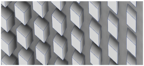
Figure 1. Hybrid rib array
The hybrid rib array used in this study is illustrated in Figure 1. The ribs are first machined and tilted at a 0° angle along the flow direction, which is completed for traditional rib structure. Next, a set of grooves with a specific angle, such as 30°, 45° or 60°, is processed to form a hybrid rib array.
In the vertical liquid box of the self-circulating system, the cooled HTF flows upward from the bottom. In the traditional rib structure, which only features a vertical main channel, the bubbles in the upper section are influenced by the bubbles flowing below, making it difficult for them to separate. However, in contrast, the bubbles in the rib grooves, auxiliary flow channel. rise obliquely and are constrained by the rib's lateral wall. The inclusion of auxiliary channels results in the creation of intermittent sections within the main channels. These provide only-lower similar regions for the bubbles to move and comfortably separate from each other in the main channel. As a result, the structure increases the probability of efficient heat transfer with a higher circling flow.
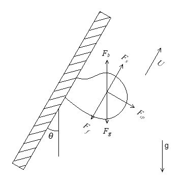
Figure 2. Forces acting on a vapor bubble flowing along rib surface
Figure 2 shows the force analysis plot for a bubble confined by a tilted wall. Where, θ is the angle between the flow and the oblique channels, Ff is the wall friction force, Fs is the shear force of the fluid in the groove, Fcp is the contact pressure, Fg is the bubble gravity and Fb is the buoyancy force.
As the spacing is designed over 2mm, the shear force only provides little power for the bubble. A component of the contact pressure also provides little power for the bubble for the small body of the bubble. However, the wall friction force exists to impede bubble flow in channel. And the net gravitational force (due to buoyancy) provides some power for the bubble along the inertia flow (U direction), which may be represented as
$F_{g, \text { net }}=\left(F_b-F_g\right) \cdot \cos \theta=\left(\rho_l-\rho_g\right) \cdot g \cdot V_{b u b b l e} \cdot \cos \theta$ (2)
where, Fg,net is net gravitational force, N; ρ is density, kg/m3; g is gravity, m2/s; Vbubble is bubble volume, m3; θ is angle between main flow and groove, °; subscript l and g are the liquid and gas phases, respectively.
As can be seen in Figure 2, the smaller the included angle, the greater the power of the HTF in the groove to raise the bubble. However, if the inclusion angle is large, the bubble may rise closer to the wall, causing perturbation. Ideally, the bubbles should accumulate to reach the notch of the oblique groove before leaving to rise vertically, minimizing local resistance.
As an auxiliary flow channel, the angle between the groove and the main flow channel should be carefully adjusted to ensure optimal performance. When the angle is too small, the directions of the two channels can mix and align, creating a structure like two parallel flows with small fin widths and spacings. Such a structure is inconsistent with the objectives of this study. In contrast, a too large angle causes these two channels to become perpendicular to each other, leading to the pin-fin structure or like. This outcome is also not desirable in the context of this study because it sacrifices the effectiveness of the auxiliary flow channel. To ensure the effectiveness and representativeness of research on the auxiliary flow channel, angles of 30°, 45° and 60° are more appropriate for comparison.
Due to the complexity of HTF flow in self-circulating systems, qualitative analysis needs to be complemented with experimental quantification. Temperature can reflect the heat transfer performance, so accurate temperature measurement and high heating flux heaters should be carefully prepared in the experimental platform. For the test structures, angles of 30°, 45° and 60° in the hybrid rib array structure are appropriate. The rib spacing is suggested more than 2mm to reduce flow resistance and simplify manufacturing. The length and width should be adjusted to make all the traditional and hybrid structures have a same heat transfer area.
The experimental platform built in this paper is shown in Figure 3. The liquid box, which act as the evaporator, is connected to the condenser by the riser and the downcomer, forming a closed loop. The heaters are arranged on either side of the liquid box, containing both the traditional rib array structure and the new hybrid one. The heating power of the heater is controlled by the Voltage regulators.
Figure 3. Experiment rig
After the heater is energized, the generated heat is transmitted to the liquid box and then absorbed by the HTF inside the box. The temperature of the HTF rises before the evaporative point is reached, after which the liquid-phase HTF changes to the gas-phase. The gas-liquid mixed HTF flows to the condenser along the riser, releases heat and condenses into the liquid phase. The liquid HTF then flows down to the liquid box under the action of gravity to participate in the next cycle.
The thermocouples were carefully calibrated by FLUKE 9171 and arranged between the heating block and the outer wall of the liquid box. The effectiveness of the enhanced heat transfer structure can be judged by comparing the wall temperature of the liquid box with different structures at the same power.
Figure 4 displays the difference in structure between the two sides of the liquid box. The left side displays a regular rib array with a continuous and straight rib. On the right side, there is a hybrid rib array that includes oblique milling of 30°, 45° or 60°, based on the same size of the rib on the left. Thermocouples are arranged in the center of the outer wall of each structure. This setup minimizes measurement errors that might arise from changes in boundary conditions, such as substituting the liquid container or filling the HTF. During the experiment, the structure with lower temperature gives better heat transfer performance.
Figure 4. Liquid box with regular rib array and hybrid rib array
Table 1. Parameters of hybrid rib array
|
Number |
Rib Height / mm |
Rib Width / mm |
Spacing / mm |
Angle / ° |
|
Model 1 |
6 |
2 |
2 |
30 |
|
Model 2 |
6 |
2 |
2 |
45 |
|
Model 3 |
6 |
2 |
2 |
60 |
|
Model 4 |
9 |
3 |
3 |
60 |
|
Model 5 |
6 |
1 |
3 |
60 |
Figure 5. Hybrid rib array structure
This study mainly focuses on two parameters: one is the effect of the angle between the oblique groove and the mainstream on the heat transfer, the other is the effect of the rib width-height ratio on the heat transfer. Therefore, we designed five types of liquid boxes, whose characteristic sizes are listed in Table 1. The physical picture of the parameters is indicated in Figure 5.
The rib width and height are carefully chosen to ensure equal heat transfer area. The spacing is equal to the rib width, so that the heat transfer region before and after oblique cut is guaranteed. This premise is very important that the temperature is meaningful only with the accuracy of temperature measurement, the same heat transfer area, and the same heating power.
As shown in Table 1, the base structure of 6mm height, 2mm width and 2mm spacing is chosen for its good performance in our previous experiments. Then, models 1 – 3 have all same parameters except different angles; models 1- 4 have the same width - height ratio of 1:3; and models 1,2,3,5 have the same height of 6mm. Thus, the differences in Table 1 on heat transfer performance will be discussed in section 4.
Customize the heater according to the size of the liquid box to ensure that is an effective heating area of 0.025 m2. In addition, the power and heat flux of the heating tested in the experiment are determined based on the heat dissipation requirements, as shown in Table 2. The bubbles in the liquid box operate in various states under different heat flux conditions. There is also a significant difference of HTF mainstream in the center and near the wall under a certain heat flux. In order to make a comprehensive comparison, four typical points of heat power were selected for experimental testing.
Table 2. Power and heat flux
|
Heat Power / W |
Heat Flux / W/m2 |
|
1000 |
40000 |
|
1500 |
60000 |
|
2000 |
80000 |
|
2500 |
100000 |
After connecting the pipe by thread, the maximum power was loaded on both sides of the liquid box, and the non-condensing gas was removed by multiple venting. After preheated, the typical heat power, according to Table 2, was loaded onto the liquid box by one side after another, respectively. All experimental data was recorded in steady state with temperature fluctuation less than 0.5℃ for more than 30 minutes.
In the experimental setup, geometries in five random locations of each board were measured and compared with the data in Table 1 to minimize processing errors. Temperature sensors were carefully calibrated just before experiments to minimize temperature measurement errors. The hybrid rib array structure with corresponding geometric parameter was tested under identical initial and testing conditions as the traditional array structure to minimize testing environment errors.
This section analyzes the influence of the angles, rib width - height ratios, and rib heights structure in the liquid box on the reduced wall temperature and enhanced heat transfer performance.
4.1 Effect of the angles on the reduced wall temperature
The temperature difference between the conventional rib arrays and the hybrid rib arrays in each liquid box was used to measure the improvement in heat transfer performance at the same heating power. The results are shown in Figure 6. Clearly, the smaller the angle, the better the enhanced heat transfer effect. The 30° hybrid rib structure reduces temperatures by 9.3℃ compared to the traditional structure under 100 kW/m2. The reduced temperature between 30° hybrid and traditional rib array is more than 1.8 times of the reduced temperature of 45° ones. With the increase of heat flux, the heat transfer performance of 60° oblique rib array is even worse, with a gained temperature of 1.7℃ under 100 kW/m2, than that of traditional rib array. The possible reason is that it is convenient for bubbles to escape from the auxiliary channel to main channel when the angle between the bevel and the mainstream direction is below 45°. When the angle is over 60°, the bubbles are difficult to escape, equal to the reduction of the effective heat transfer area, which leads a deterioration of the heat transfer.
Figure 6. Reduced temperature between hybrid and traditional rib array
4.2 Influence of rib width - height ratios on heat transfer performance
Figure 7. Temperature on traditional rib side
Table 1 presents that Model 3 and Model 4 have a rib width-height ratio of 1:3, whereas Model 5 has a rib width-height ratio of 1:6. And the Figure 7, on the other hand, demonstrates that the efficiency of heat transfer improves with a larger aspect ratio of the conventional rib array.
The experimental results show that Model 3 and Model 4 have significantly lower wall temperatures than Model 5. This dissimilarity is mainly attributed to the small thermal conductivity cross-section of Model 5, leading to a larger thermal resistance at the same power. As the total heat transfer area and angle are the same for Model 3, 4 and 5, one model with lower metal thermal resistance has a higher overall heat transfer coefficient and a superior heat transfer performance compared to others. In the metal heat transfer section, heat is conducted from the bottom to the top. Hence, the thermal resistance is proportional to height and inversely proportional to the width (effective cross-sectional area). Therefore, an increased width - height ratios, such as 1:3, leads to a reduced overall thermal resistance and better heat transfer performance than the lower, such as 1:6. Moreover, a better performance is observed in Model 3 compared to Model 4, which can be attributed to its lower rib height and shorter heat transfer path.
4.3 The influence of heights between hybrid rib arrays on heat transfer performance
Figure 8 presents the data illustrating the lower temperature and better heat transfer performance of Model 3 and Model 4 compared to Model 5 when exposed to a heat flux of 80 kW/m2 heat flux or lower. While Model 4 exhibits better heat transfer performance than Models 3 and 5 when subjected to a heat flux of 100 kW/m2. This is attributed to the higher and wider HTF channel in Model 4, with hydraulic diameter of 4.5mm, than others. The feedback HTF flows more rapidly in this low flow resistance channel in Model 4 than others, resulting in a higher frequency of bubble emergence and disengagement than in the other structures. Thus, the large height and spacing gain the heat transfer performance under huge heat flux condition.
Figure 8. Temperature on hybrid rib array side
This study has investigated the heat transfer performance of a novel hybrid rib array heat exchanger, focusing on the effects of angle, width-height ratio, rib heights and spacings on the heat transfer process. In this paper, a new hybrid rib array heat exchanger is proposed. Its heat transfer performance has been analyzed both theoretically and experimentally. The experimental results on the self-circulating experiments show that:
(1) The hybrid rib array heat exchanger with 30° angel significantly enhances the heat transfer performance compared to the other 45° and 60° angles tested. And the 30° hybrid rib structure reduces even 9.3℃ compared to the traditional structure under 100 kW/m2 condition;
(2) In the case of the straight rib, the 1:3 width-to-height ratio of the rib section improves the heat transfer effect instead of the 1:6 ratio one. That is mainly because the thermal resistance in metal region with 1.3 width-to-height ratio is lower than that with 1:6;
(3) Regarding hybrid rib arrays, the heat transfer effect is jointly influenced by rib width, spacing and height. Under 80 kW/m2 or less, higher width-to-height ratio performs better heat transfer. Under 100 kW/m2 or more, the large height and spacing gain the heat transfer performance.
[1] Cohen, M., Carry, V.P. (1989). A comparison of the flow boiling performance characteristics of partially-heated cross-ribbed channels with different rib geometries. International Journal of Heat and Mass Transfer, 32(12): 2459-2474. https://doi.org/10.1016/0017-9310(89)90205-6
[2] Ohara, T., Yamamoto, T., Fujita, H. (1990). Heat transfer and pressure drop of boiling flow in a cross-ribbed flat channel. International Communications in Heat and Mass Transfer, 17(5): 555-566. https://doi.org/10.1016/0735-1933(90)90004-4
[3] Kong, L., Liu, Z., Jia, L., Lv, M., Liu, Y. (2020). Experimental study on flow and heat transfer characteristics at onset of nucleate boiling in micro rib fin heat sinks. Experimental Thermal and Fluid Science, 115: 109946. https://doi.org/10.1016/j.expthermflusci.2019.109946
[4] Qi, D., He, J., Xu, Y., Lin, M., Wang, Q. (2022). Effect of rib diameter on flow boiling heat transfer with staggered rib arrays in a heat sink. Energy, 239. https://doi.org/10.1016/j.energy.2021.122323
[5] Niezgoda-Żelasko, B., Żelasko, J. (2015). Refrigerant boiling at low heat flux in vertical tubes with heat transfer enhancing fittings. International Journal of Refrigeration-revue Internationale Du Froid, 54: 151-169. https://doi.org/10.1016/j.ijrefrig.2015.03.007
[6] Kuznetsov, V.V., Shamirzaev, A.S., Ershov, I.N. (2007). Heat transfer in boiling and ascending flow modes in vertical rectangular small-size channels. Heat Transfer Research, 38(6): 483-493. https://doi.org/10.1615/HeatTransRes.v38.i6.10
[7] Yan, L., Li, H., Li, L., Wu, C. (2014). Bubble behavior of flow boiling in horizontal rectangular channels with inclined ribs. International Journal of Heat and Mass Transfer, 75: 514-522. https://doi.org/10.1016/j.ijheatmasstransfer.2014.03.068