U Ubaidillah*![]() | Bioma Cakrawala | Indri Yaningsih
| Bioma Cakrawala | Indri Yaningsih![]()
© 2023 IIETA. This article is published by IIETA and is licensed under the CC BY 4.0 license (http://creativecommons.org/licenses/by/4.0/).
OPEN ACCESS
Currently there are many online food delivery services. Customers simply order food via smartphone, the food will be delivered by the service provider. Long delivery times, or when the weather is cold can result in food not being fresh. Recently several studies had been carried out on food delivery boxes that utilize the heat generated from the combustion of motorbikes, where the exhaust gas was channeled directly into the heating chamber inside the box. This design allows gas leaks which can poison food. Therefore, in this research a food delivery box will be developed that utilizes motorcycle exhaust heat with additional fluid. The flue gas does not come into direct contact with the box, making it safer for use in food delivery. The research was carried out by designing two types of prototypes, CFD simulations to analyze heat transfer, to testing. The main difference between the two designs lies in the location of the inlet and outlet. Testing of both designs was carried out at three speed variations, including 10 kph, 20 kph and 30 kph. The experimental results that had been carried out on the first design show that the prototype can work well in keeping the food temperature warm. The simulation results performed on both designs also show good performance. But when compared, the second design is much better than the first design, because it has a better flow distribution.
food delivery box, heat transfer, ANSYS fluent, CFD, waste energy
Vast growing technology has significantly impacted the way food is marketed online. With the rise of e-commerce and social media, online food marketing has become an integral part of the food industry. By leveraging the latest technological advancements, food businesses can reach a wider audience and promote their products more effectively. From creating attractive food photography and videos to using innovative marketing techniques such as augmented reality, technology is allowing food marketers to engage with their customers in new and exciting ways. In addition, technology has also enabled food businesses to streamline their operations, making it easier to manage orders, track inventory, and process payments. By embracing technology change, food marketers can stay ahead of the competition and meet the evolving demands of their customers
These technological changes have affected the food delivery service system, telephone-based ordering has now turned online [1]. The existence of the internet and technology had triggered the emergence of Online Food Delivery (OFD) through online market applications [2]. An internet-based food ordering and delivery system for Online Food Delivery (OFD) services connects customers with partner restaurants through a mobile application [3]. Food ordered online is prepared and delivered to consumers [4]. When a customer orders at a restaurant through the OFD service platform on a mobile application and pays for the order, the restaurant receives the order and prepares the food immediately, then the order is delivered to the customer. Order status can be tracked through the application; besides that, customers can also interact with drivers [5].
The annual growth rate (CAGR 2022-2027) of revenue in the Online Food Delivery market in Indonesia is estimated at 24.21% [6]. Indonesia's Internet economy has more than quadrupled since 2015 with an average growth rate of 49% per year [7]. Many food delivery applications had grown in Indonesia in recent years. The research results of Tenggara Strategics show that the majority of consumers in Indonesia have more than 1 food delivery application on their smartphones, with a percentage reaching 72% [8]. 60.6% of consumers in Indonesia use Online Food Delivery (OFD) services since they enjoy the convenience of the services offered [9].
The average online food delivery time in Indonesia is 29 minutes [10]. Long distances, long delivery times, or rainy weather cause food to be cold when received by consumers so that it can reduce the taste or change the texture of food [11-13]. Improper delivery of food can promote the growth of harmful foodborne pathogens such as E. coli, which can cause diarrhea, sometimes bloody, with acute abdominal cramps for three to seven days after infection [14]. To maintain good food quality, the box where food is placed must have a temperature of around 50℃–60℃ [15], whereas according to Food Safety and Inspection Service regulations, hot food must not be sent at temperatures below 60℃ [16]. If food is delivered warmly then customers get more satisfaction and this will attract more customers to order food online which can increase business [17].
Many food service companies deliver their orders using cars or motorbikes which emit a lot of exhaust gas [18]. In moving motorized vehicles, there is residual heat flowing into the exhaust and the percentage is quite large when compared to heat loss through cooling media, lubrication and other losses in the prime mover. The greater the number of engine revolutions and the distance traveled by a motorized vehicle, the greater the heat generated. This waste heat is wasted in the environment. Even though it should be reused to be converted into other forms of energy or transferred as needed [19]. Utilization of exhaust heat, can reduce the impact of global warming and reduce exhaust emissions [20].
Thamrin and Sanap investigated the use of exhaust gas in food delivery boxes. Specifically, they looked into two designs that used this method, both of which have similar systems. In this design, the exhaust gases are directed directly to the insulated box. The heat from the gas is then transferred to the walls of the box, causing the temperature inside the box to rise and the food to stay warm.
However, in this study it has been found that there are several developments that can be applied to this method. When the motorcycle engine is turned off, the temperature inside the box will drop, which means the food won't stay warm for very long. These problems inspire developers to conduct further research and develop new systems that can overcome these limitations.
The newly designed system involves adding a liquid in the form of water to a food delivery box. This liquid will be used to distribute heat more evenly throughout the box, which will help keep food warm for a longer time even after the motorcycle engine has been turned off.
Thamrin and Sanap's research demonstrates the potential of using exhaust gas in food delivery boxes, but also highlights the need for further innovation to optimize the performance of these systems. By developing new and innovative ways to distribute heat more efficiently, it is possible to create more effective and reliable food delivery boxes that can keep food warm and fresh for a longer period of time.
Therefore, in this research a food delivery box will be developed that utilizes motorcycle exhaust heat with added liquid. The flue gas does not come into direct contact with the box, making it safer for use in food delivery. The research was carried out by designing two types of prototypes, CFD simulations to analyze heat transfer, to testing. The main difference between the two designs lies in the location of the inlet and outlet.
The results of the study present an analysis of the design of a food delivery prototype design that utilizes exhaust gas heat on motorcycle. The design of the new prototype design was carried out based on the initial prototype that had been previously designed. The design of the new prototype design was carried out by analyzing design for manufacture and assembly, as well as conducting heat transfer analysis using analytical methods and computational fluid dynamics (CFD). The temperature data obtained in the initial prototype experiment will be used to analyze the heat transfer in the new prototype design.
2.1 Theory and design
In this study, the performance of the two food delivery box designs was analyzed using the convection and conduction approaches. Convection is a mode of energy transfer between a solid surface and an adjacent moving liquid or gas, and it involves the combined effects of conduction and fluid motion. The faster the fluid motion, the greater the convection heat separation [21]. The rate of convection heat loss is expressed by Newton's law of cooling as:
$\dot{Q}_{conv}=h A_s\left(T_s-T_{\infty}\right)$ (1)
where, $\dot{Q}_{conv}$ is the convection heat insulation layer (W), h is the convection heat locking coefficient (W/m2.℃), As is the surface area where convection heat separation occurs (m2), Ts is the surface temperature (℃), and T∞ is the temperature of the fluid far enough from the surface (℃). Conduction is the locking of energy from more energetic particles of a substance to adjacent less energetic particles as a result of interactions between particles [21]. The conduction heat insulation rate is expressed by Fourier's law of heat conduction as:
$\dot{Q}_{c o n d}=-k A \frac{d T}{d x}$ (2)
where, $\dot{Q}_{cond}$ is the degree of heat insulation conduction (W), k is the thermal conductivity of the material (W/mK), A is the area over the direction of heat insulation (m2) and dT/dx is the temperature gradient.
The prototype design was created using Fusion 360, which is a design platform from Autodesk. Fusion 360 integrates structural design, industrial design, CAM, and mechanical simulation [22]. In this study, two food delivery box designs were designed with the same work system, but there were differences in configuration and water flow patterns in the boxes. The inlet and outlet of the box are connected to the inlet and outlet of the heat exchanger mounted on the muffler. The heat carried by the flue gas flow will propagate towards the water in the heat exchanger.
Induction motors are often applied to water pumps due to their high efficiency, low cost, robustness, availability in the local market [23]. Brushless DC (BLDC) motors are better than induction motors, have good efficiency and low noise [24]. Therefore, a BLDC pump was used in this study. The BLDC pump will circulate the water in the heat exchanger into the box, so that the temperature of the food room will increase over time.
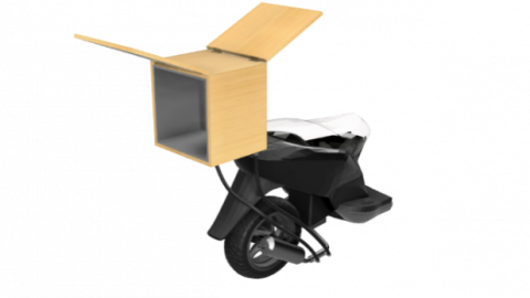
(a) Isometric view
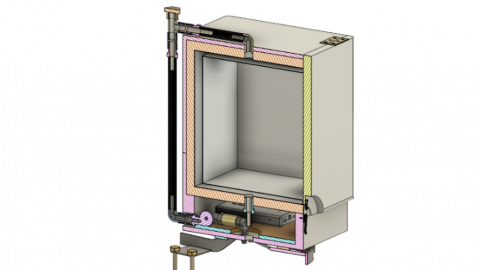
(b) Section view
Figure 1. First design
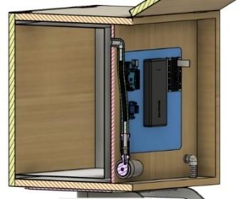
Figure 1(a) shows an isometric view of the first design, while Figure 1(b) shows a cross-sectional view of the first design, where the water inlet and outlet are located at the back of the box. The food room and water room were made using materials that are sturdy and corrosion resistant, namely stainless steel 201. Stainless steel AISI 201 has good corrosion resistance since it contains 18 wt.% chromium, 3 wt.% nickel, and 7 wt.% to stabilize austenitic phase [25]. The food room and water room are insulated using a sandwich material to reduce heat dissipation. The structure of the sandwich material is light and very strong [26], has the ability to withstand shear stress and tensile stress [27]. On the back there is a water pump and an electronic circuit (See Figure 2) used to control the pump and read the temperature in the food room. The first material configuration and design dimensions are presented in Table 1.
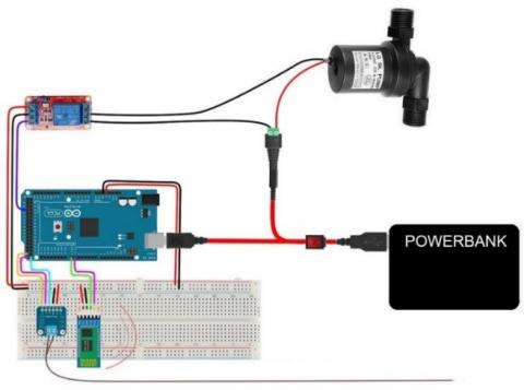
Figure 2. Wiring diagram
Table 1. First design configuration
|
Parameter |
Value |
|
Food room dimension |
(370×240×370) mm |
|
Food room volume |
32,856 mm3 |
|
Food room wall thickness |
1 mm |
|
Water room dimension |
(390×290×390) mm |
|
Water room volume |
11,235 mm3 |
|
Water hole diameter |
25.4 mm |
|
Heat exchanger length |
150 mm |
|
Heat exchanger inner diameter |
25 mm |
|
Heat exchanger outer diameter |
40 mm |
|
Hose length |
1,000 mm |
|
Insulator dimension |
(420×420×420) mm |
|
Insulator thickness |
18 mm |
Table 2. Second design configuration
|
Parameter |
Value |
|
Food room dimension |
(280×250×280) mm |
|
Food room volume |
19,600 mm3 |
|
Food room surface area |
0.358 m2 |
|
Water room volume |
7,400 mm3 |
|
Wall thickness |
0.5 mm |
|
Insulator dimension |
(300×300×300) mm |
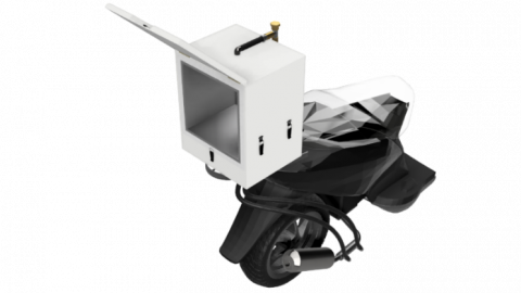
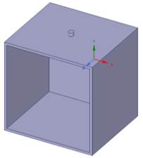
Figure 3(a) shows an isometric view of the second design, while Figure 3(b) shows a portion of the second design, where the water inlet and outlet are located at the top and bottom of the water room, respectively. The food room and water room areas were made using 201 stainless steel sheets insulated using ABS plastic. At the bottom there is a water pump and an electronic circuit that is used to control the pump and read the temperature in the food room. Both designs have the same heat exchanger and circuitry. Material configuration and second design dimensions are presented in Table 2.
(a) Isometric view
(b) Section view
Figure 3. Second design
2.2 Experimental setup
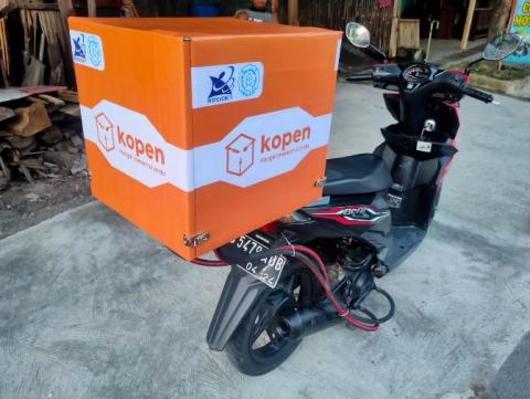
After completing the first design prototype, it proceeded to conduct the first performance experiment. To do this, a Honda Beat FI motorcycle with a cylinder capacity of 110 cc was used. It's worth noting that the motorcycle was not driven on the road during the experiment; instead, it was operated in a controlled environment with a focus on steady condition using the maindstand (kick stand), as shown in Figure 4. The throttle was opened till the temperature of the exhaust passed the target to warm the box.
Figure 4. Experiment
The main objective of this experiment was to collect temperature data on the first design prototype. By measuring the temperature inside the prototype under different conditions, the researchers could evaluate its performance and identify any potential issues that needed to be addressed.
Overall, this experiment was a critical step in the development of the prototype, as it provided important insights into its functionality and effectiveness. With the data collected from this experiment, the researchers could refine the design and make any necessary adjustments to optimize its performance. This, in turn, would help to ensure that the final product was capable of keeping food warm and fresh for extended periods of time, even when the motorcycle engine was turned off.
Data collection was carried out using a thermocouple. The use of probes is very simple, cheap, accurate and easy to use [28]. The probe was placed at a predetermined point, as shown in Table 3. The thermocouple probe was installed at the inlet and outlet of exhaust gas, water inlet and outlet, wall of the food room, food room, food and air outside the system.
Table 3. Placement of the thermocouple probes
|
Section |
Probe Location |
|
Heat exchanger |
Gas inlet |
|
Gas outlet |
|
|
Water inlet |
|
|
Water outler |
|
|
Box |
Food room wall |
|
Food room |
|
|
Food |
|
|
Environment |
2.3 Simulation setup
CFD is a system analysis related to heat combustion, fluid flow, and related phenomena such as chemical reactions using simulation with computer technology [29]. In this study, CFD simulation was carried out to determine the contours of the temperature distribution in the food box. The entire simulation process was carried out using the Ansys Workbench software. The geometry that had been drawn with Fusion 360 software was then pasted into Ansys SpaceClaim. The design was then converted into a mesh form.
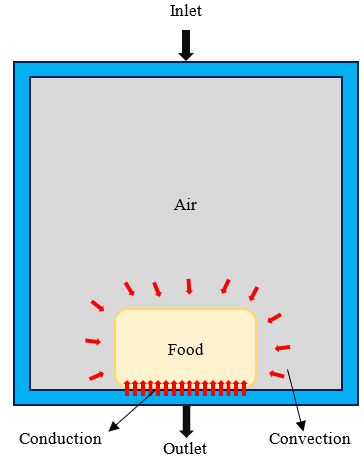
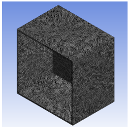
In this study, CFD simulation is only focused on food boxes, with the simulation domain as shown in Figure 5. The simulation domain is the fluid in the water room. The outside of the box is considered to be completely insulated so that there is no heat exchange with the surroundings. The geometry and mesh results of the first design are shown in Figure 6. The mesh settings applied to the first design are presented in Table 4.
The ideal mesh result is one that is uniform in all directions and converges. However, in reality the mesh results cannot reach ideal conditions. Several factors that affect the mesh include the arrangement of elements, the aspect ratio of elements, and sudden changes in the mesh [30]. After meshing, the next process was Computational Fluid Dynamics (CFD) using Ansys Fluent. The parameters entered in the simulation setup are the same as the parameters used during the experiment. The simulation parameters are presented in Table 5.
Figure 5. Schematic of heat transfer in the food room
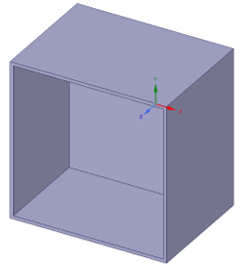
(a) 3D design
(b) Meshing
Figure 6. First design geometry
Table 4. Mesh settings in the first design
|
Parameter |
Value |
|
Element shape |
Tetrahedron |
|
Element size |
7 mm |
|
Number of elements |
389,736 |
|
Number of nodes |
159,653 |
Table 5. CFD simulation parameters in the first design
|
Parameter |
Value |
|
Gravitation |
9.81 m/s2 |
|
Flow |
Turbulent |
|
Flow velocity |
0.44 m/s |
|
Number of steps |
3,000 |
|
Time step size (s) |
0.1 |
|
Max iteration/time step |
5 |
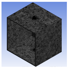
The simulation carried out in the second design uses the same settings as the simulations carried out in the first design, where the results of the first design simulation had been verified with the experimental results of the first design prototype. The geometry and mesh results of the second design are shown in Figure 7. The simulation parameters are presented in Table 6, while the simulation parameters entered in the setup and simulation sections are the same as the first design parameters.
(a) 3D Design
(b) Meshing
Figure 7. Second design geometry
Table 6. CFD simulation parameters in the second design
|
Parameter |
Value |
|
Element shape |
Tetrahedron |
|
Element size |
7 mm |
|
Number of elements |
227,821 |
|
Number of nodes |
103,594 |
3.1 Experimental results
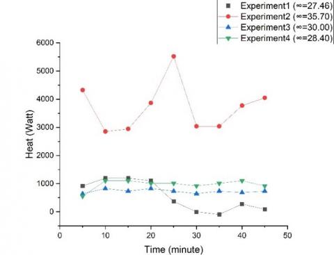
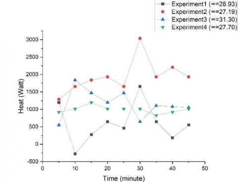
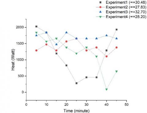
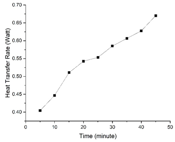
The throttle lever was pulled constantly with three variations of motorcycle speed, namely 10 kph, 20 kph, and 30 kph. Data collection was done every 5 minutes. Figure 8 shows the rate of heat transfer released by water and then absorbed by the food box and released into the environment. The DC water pump circulated water at a speed of 0.44 m/s, where the water passed through the heat exchanger mounted on the exhaust, through the hose, then entered the water room of the food box, and exited to the heat exchanger through the hose. This cycle occurred continuously for 45 minutes. The experimental results show that the heat transfer rate is not uniform, even at certain times it shows a negative value, this means that the heat from the food box is absorbed by water. The heat exchanger installed in the exhaust is in direct contact with the environment, so that quite a lot of heat is wasted into the environment.
(a) 10 kph
(b) 20 kph
(c) 30 kph
Figure 8. Heat transfer rate released by water at different motorcycle speeds
Hoses and boxes are not properly insulated, this is enough to reduce the efficiency of the prototype due to the heat being wasted into the environment. This difference is strongly influenced by environmental conditions, including air temperature and wind speed. Since each experiment was carried out under different environmental conditions, the heat transfer that occurs was also not uniform.
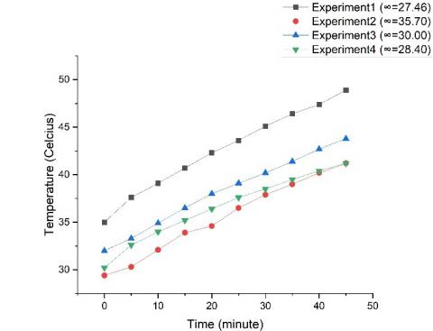
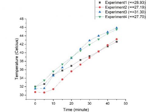
(a) 10 kph
(b) 20 kph
(c) 30 kph
Figure 9. Food room wall temperature at different motorcycle speeds
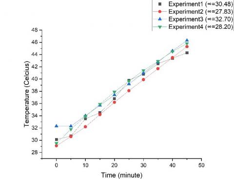
Water carrying heat was pumped throughout the system, the heat will be absorbed by the food delivery box made of stainless steel, or lost to the environment. The temperature on the walls of the food room will continue to increase over time due to the accumulation of heat. Figure 9 shows an almost constant rate of temperature increase in each experiment. The speed of the motorcycle affects the rate of heat transfer in the prototype, this is since the more the gas lever pulls, the higher the combustion temperature in the IC engine combustion room so that the heat that propagates towards the water is greater. In addition to the speed of the motorcycle, the temperature of the walls of the food room is greatly influenced by the temperature of the water and the environment.
Experiments were carried out at different ambient temperatures, where the temperature of the ground water used, as well as the ambient air temperature were affected by the ambient temperature. The wall temperature at a speed of 30 kph carried out in experiments 1 to 4 showed almost uniform values, due to the difference in ambient temperature was not too significant. The heat on the walls of the food room will then be used to heat the food in it.
Water circulates along the water channel, when it enters the heat exchanger, the water will absorb heat from the exhaust gases of the motorcycle engine combustion. To simplify calculations, it is assumed in this analysis that the entire system was perfectly isolated, so that no heat was wasted into the environment.
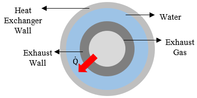
Therefore, the heat released by the water in the box is equal to the heat absorbed by the water in the heat exchanger. Figure 10 shows a schematic of heat transfer that occurs in a heat exchanger. Water that has entered through the inlet channel will release heat on the walls of the food room. The heat that has been absorbed by the wall will transfer to the food placed in the food room. There are three modes of heat transfer in the food room, namely conduction that occurs between the surface of the food in contact with the surface of the wall, convection that occurs between the food and the air in the food room, and radiation emitted by the wall of the food room. However, in this study the radiation heat transfer was not analyzed.
Figure 10. Schematic of heat transfer in the heat exchanger
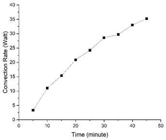
The assumptions applied include, among others, that the entire system is perfectly isolated so that no heat escapes to the environment; all the heat coming from the heat exchanger is absorbed by the walls of the food room; the rate of heat transfer released by water to the walls of the food room is constant; and the mass flow rate of water in the box is constant. Based on the calculations that have been done, the rate of convection heat transfer that occurs in the food space when the speed of the motorbike is traveling at a speed of 20 kph is shown in Figure 11, the graph in the figure shows an increase in the convection rate with increasing time.
Figure 11. Convection rate in the food room when the motorcycle speed is 20 kph
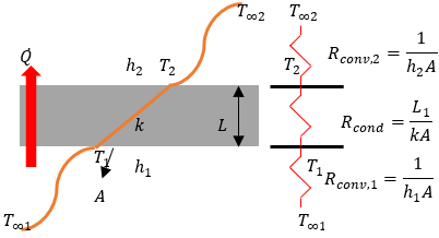
For food that is in direct contact with the surface of the wall, heat transfer can occur through conduction. The rate of conduction heat transfer in food in direct contact with the wall can be obtained using thermal resistance as shown in Figure 12. In the experiment, a piece of white bread was placed in the food room for analysis. The rate of heat transfer on the walls of the food room is obtained as shown in Figure 13.
Figure 12. Thermal resistance on the food room wall
Figure 13. The rate of heat transfer on the walls of the room when the motorcycle speed is 20 kph
Based on the analysis conducted on the experimental data and the first design CFD simulation, several conclusions can be drawn, including:
The average heat transfer rate that can be absorbed by the walls of the food room is 991.6 Watt. The rate of heat transfer is influenced by the value of the thermal conductivity of stainless steel and the thickness of the plate on the wall of the food room. Poor thermal insulation system and environmental conditions also affect the rate of heat transfer that occurs.
The food room wall temperature that can be achieved at the three speed variations ranges from 30.3℃ to 46.3℃.
The results of the CFD computation show that the configuration of the water inlet and outlet holes in the first design cannot distribute heat evenly in the water room, so that the residual heat from the engine combustion cannot be utilized optimally.
3.2 Simulation setup
The water temperature at the inlet, wall, and outlet was taken based on experimental data 4 at a motorcycle speed of 20 kph, while the fluid and metal properties were set on Ansys Fluent. With a total of 3,000 time steps and a large step size of 0.1, a simulation time of 300 seconds or 5 minutes is obtained, according to the time intervals carried out during the experiment. The computations that have been carried out have produced temperature contours on the walls of the food room as shown in Figure 14 as follows.
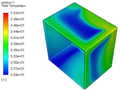
(a) Isometric view
(b) Front view
Figure 14. The contour of the food room wall temperature in the first design
Water enters the water room through a hole near the top corner of the back of the box, and exits through a hole near the bottom corner of the back of the box. The configuration of the water inlet and outlet holes produces the flow pattern shown in Figure 14. Most of the wall surfaces are dark blue to light blue with a temperature range between 32.4℃ to 33.2℃. Most of the green contours are on the edge of the food room with a temperature range between 33.2℃ to 34.1℃. While the yellow and red contours are only present near the inlet in small quantities, with a temperature range between 33.4 ℃ to 35.2℃.
The second design simulation was carried out with three variations of motorcycle speed, namely 10 kph, 20 kph, and 30 kph, with the initial temperature at the water inlet and the wall of the food room taken based on the experiments carried out in the first design. Assuming the water wall temperature is the same as the food room wall temperature, the initial wall temperature data during the experiment is used as the initial fluid wall temperature data in the simulation.
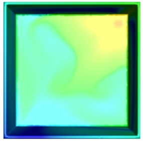
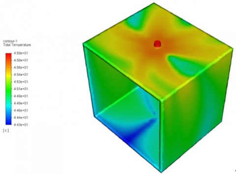
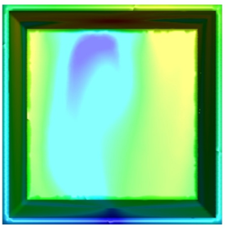
The CFD simulation results from the three speed variations show the same temperature contour, so that only the contours of one of the speed variations are shown, namely at 20 kph as shown in Figure 15. The figure shows a fairly even temperature distribution on the walls of the food room, where most of the color contours on the surface of the box are green which indicates an average temperature of 45.1℃. At the inlet, the color contour is dominated by red and orange, which indicates an average temperature of 45.8℃. While at the outlet, the color contour is dominated by blue which indicates an average temperature of 44.4℃.
(a) Isometric view
(b) Front view
Figure 15. The contour of the food room wall temperature in the second design
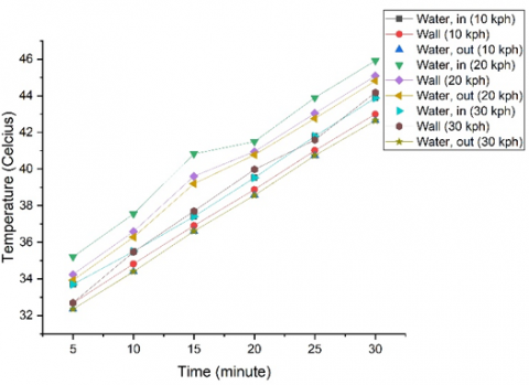
From the simulation results that have been carried out, the temperature data on the walls of the food room is obtained, the temperature of the water at the inlet and water at the outlet of the box for each variation of motorcycle speed, as shown in Figure 16. The three graphs on this show almost the same gradient, so with this pattern the temperature at the next time can be predicted just by looking at the graph. The initial temperature on the graph is not the same, due to the data is taken based on experimental data that has been done.
Figure 16. Second design CFD simulation results
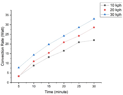
Assuming all the heat coming from the heat exchanger is absorbed by the walls of the food room, then based on the calculations made in the first design, the heat transfer rate is 991.6 Watts. The scheme of heat transfer that occurs in the food room is shown in Figure 10. By assuming the difference between the food room temperature and the food wall surface temperature in the second design is the same as the first design, the food room temperature entered in the simulation is taken based on experimental data, while the food room wall temperature is obtained through simulation. The results of the analysis of the rate of convection heat transfer that occur in the food space at each variation of the speed of the motorcycle are shown in Figure 17.
Figure 17. Convection rate in the food room in the second design
The rate of heat transfer convection shown in Figure 17 has a smaller value than the convection heat transfer rate that occurred in the first design. This difference is due to the dimensions of the second design which is smaller than the dimensions of the first design. Hence the surface area of the second design is smaller than the counterpart. This discrepancy affects the rate of heat transfer. In this study, it is assumed that there is still air in the food space, thus allowing convection to occur.
3.3 Design comparison
Figure 18 shows a comparison of the wall temperature of the food room of the two designs at a predetermined motorcycle speed.
Figure 18. Comparison of the food room wall temperature in the first design and the second design
Based on the analysis that has been done on both designs, the second design has better heating capability than the first design. The second design has better capabilities due to the water inlet and outlet configurations can distribute heat more evenly to the walls of the food room than the first design.
In addition, the second design wall has a thinner thickness, which is 0.5 mm, while the first design wall thickness is 1 mm. The wall thickness of the food room affects the thermal resistance in the food room, where the thicker the wall, the more thermal resistance increases, so that it can inhibit the heat transfer that occurs.
The results of the analysis showed that at 10 kph, 20 kph, and 30 kph motorcycle speeds, the average temperature of the food room walls achieved for 30 minutes was 43℃, 45.1℃, respectively, and 44.2℃ with convection heat transfer rates of 17.5 Watt, 22.75 Watt, and 26.25 Watt, respectively. This can be achieved best if the food room and water hose are properly insulated so as to prevent or reduce the amount of heat that is wasted into the environment. Based on the results of the analysis, it was found that the temperature of the food room walls increased as the speed of the motorcycle increased, with the highest average temperature being achieved at 20 kph. The convection heat transfer rates also increased with increasing motorcycle speed, indicating that more heat was being transferred to the food room walls. To maintain the quality and safety of the food being stored in the food room, it is important to keep the temperature of the walls within a certain range. In this study, the temperature of the walls exceeded the recommended temperature of 40℃, which could potentially lead to food spoilage and contamination. To prevent or reduce the amount of heat wasted into the environment and maintain the temperature of the food room walls, proper insulation of the food room and water hose is recommended. Insulation can help to reduce heat transfer between the food room and the environment, and prevent temperature fluctuations that could negatively impact food quality and safety. Overall, the study highlights the importance of maintaining appropriate temperatures in food storage areas and the role that insulation can play in achieving this goal. By implementing proper insulation practices, organizations can help to ensure that their food storage areas remain at optimal temperatures, reducing the risk of food spoilage and contamination, and maintaining food quality and safety. However, the research was carried out on beat motorcycles with a cylinder capacity of 110 cc. The test was carried out with the condition that the motorcycle was not driving on the road (the actual delivery process was not carried out), but the engine was turned on using a stationary gas rotation/opening. Subsequent research is more focused on developing a temperature control box that can be used for various types of food.
Authors thank to Universitas Sebelas Maret for the financial support through Hibah Penelitian Unggulan Terapan 2023, LPPM-UNS.
|
A |
surface area, m2 |
|
h |
heat transfer coefficient, W/m2.K |
|
k |
thermal conductivity coefficient, W/m.K |
|
L |
length, m |
|
$\dot{Q}$ |
heat transfer rate, W |
|
R |
thermal resistance, K/W |
|
T |
temperature, K |
|
Subscripts |
|
|
$\infty$ |
infinity |
|
cond |
conduction |
|
conv |
convection |
[1] Euromonitor International. 100% Home Delivery/Takeaway. https://www.euromonitor.com/100-home-delivery-takeaway, accessed on Dec. 27, 2021.
[2] Aprilianti, I., Amanta, F. (2020). Memajukan Keamanan Pangan pada Layanan Pesan Antar Makanan Daring di Indonesia.
[3] Ray, A., Dhir, A., Bala, P.K., Kaur, P. (2019). Why do people use food delivery apps (FDA)? A uses and gratification theory perspective. Journal of Retailing and Consumer Services, 51: 221-230. https://doi.org/10.1016/j.jretconser.2019.05.025
[4] Li, C., Mirosa, M., Bremer, P. (2020). Review of online food delivery platforms and their impacts on sustainability. Sustainability, 12(14): 1-17. https://doi.org/10.3390/su12145528
[5] The Other Stream. What are the Benefits of Online Ordering Food. https://www.theotherstream.com/what-are-the-benefits-of-online-ordering-food/, accessed on Dec. 27, 2021.
[6] Statista – Online Food Delivery – Indonesia. https://www.statista.com/outlook/dmo/online-food-delivery/indonesia?currency=usd, accessed on Dec. 20, 2022.
[7] Google – e-Conomy SEA 2019: Swipe up and to the right: Southeast Asia’s $100 billion internet economy. Stephanie Davis, Rohit Sipahimalani, Florian Hoppe, Weisheng Lee, Iñaki Moreno Girona, Crystal Choi, Well Smittinet October 2019. https://www.thinkwithgoogle.com/intl/en-apac/consumer-insights/consumer-trends/e-conomy-sea-2019-swipe-up-and-to-the-right-southeast-asias-100-billion-internet-economy/, accessed on Dec. 20, 2022.
[8] Annur, C.M. Databoks – 7 dari 10 Konsumen Indonesia Punya Lebih dari 1 Aplikasi Pesan Antar Makanan. https://databoks.katadata.co.id/datapublish/2022/06/16/7-dari-10-konsumen-indonesia-punya-lebih-dari-1-aplikasi-pesan-antar-makanan, accessed on Dec. 5, 2022.
[9] Rizaty, M.A. Databoks – Grab: Kenyamanan Jadi Alasan Utama Konsumen Gunakan Layanan Pengiriman Makanan via Daring. https://databoks.katadata.co.id/ datapublish/2021/09/27/grab-kenyamanan-jadi-alasan-utama-konsumen-gunakan-layanan-pengiriman-makanan-via-daring, accessed on Dec. 5, 2022.
[10] Grab – GrabFood Rayakan Sejumlah Pencapaian Terbaru di Indonesia. https://www.grab.com/ id/press/others/grabfood-rayakan-sejumlah-pencapaian-terbaru-di-indonesia/, accessed on Dec. 5, 2022.
[11] Sanap, N.B., Mate, D.M., Kathwate, S.D. (2018). Design, analysis and performance evaluation of hybrid exhaust gas heat recovery device to keep food delivery items warm. International Journal for Advance Research and Development, 3(5): 44-56.
[12] Rial, J.A. (1996). Food-warming arrangement for a food-delivering motor vehicle. U.S. Patent and Trademark Office.
[13] Vallee, G.E., Eheander, J. (2017). Development of a motorcycle food delivery system from an international perspective. ASME International Mechanical Engineering Congress and Expositio, 58400. https://doi.org/10.1115/IMECE2017-70343
[14] Cassin, M.H., Lammerding, A.M., Todd, E.C., Ross, W., McColl, R.S. (1998). Quantitative risk assessment for Escherichia coli O157: H7 in ground beef hamburgers. International Journal of Food Microbiology, 41(1): 21-44. https://doi.org/10.1016/S0168-1605(98)00028-2
[15] Tempo – Knalpot Penghangat Pizza. https://majalah.tempo.co/edisi/598/2010-10-11, accessed on Dec. 27, 2021.
[16] Hasan, A., Dincer, I. (2020). Investigation of New Insulation Materials for Environmentally-Benign Food Delivery Bags. In Environmentally-Benign Energy Solutions, pp. 751-777. https://doi.org/10.1007/978-3-030-20637-6_37
[17] Ornektekin, S. (1998). Effect of exhaust gas on corrosion of metals. International Journal of Environmental Studies, 55(3): 199-210. https://doi.org/10.1080/00207239808711177
[18] Cherry, C.R., Weinert, J.X., Xinmiao, Y. (2009). Comparative environmental impacts of electric bikes in China. Transportation Research Part D: Transport and Environment, 14(5): 281-290. https://doi.org/10.1016/j.trd.2008.11.003
[19] Thamrin, I., Hadi, S. (2013). Studi Eksperimental Pemanfaatan Temperatur Gas Buang dari Kendaraan Bermotor Roda Dua untuk Pemanas Kotak Makanan (Delivery Box) pada Layanan Pesan Antar. Jurnal Energi dan Manufaktur, 6(2): 143-150.
[20] Saidur, R., Rezaei, M., Muzammil, W.K., Hassan, M.H., Paria, S., Hasanuzzaman, M. (2012). Technologies to recover exhaust heat from internal combustion engines. Renewable and Sustainable Energy Reviews, 16(8): 5649-5659. https://doi.org/10.1016/j.rser.2012.05.018
[21] Cengel, Y.A. (2002). Heat transfer a practical approach. 2nd Edition, McGraw-Hill, New York.
[22] Song, P.P., Qi, Y.M., Cai, D.C. (2018). Research and application of autodesk fusion360 in industrial design. In IOP Conference Series: Materials Science and Engineering, 359(1): 012037. https://doi.org/10.1088/1757-899X/359/1/012037
[23] Caracas, J.V.M., de Carvalho Farias, G., Teixeira, L.F.M., de Souza Ribeiro, L.A. (2013). Implementation of a high-efficiency, high-lifetime, and low-cost converter for an autonomous photovoltaic water pumping system. IEEE Transactions on Industry Applications, 50(1): 631-641. https://doi.org/10.1109/TIA.2013.2271214
[24] Singh, B., Bist, V. (2014). A BL-CSC converter-fed BLDC motor drive with power factor correction. IEEE Transactions on Industrial Electronics, 62(1): 172-183. https://doi.org/10.1109/TIE.2014.2327551
[25] Chuaiphan, W., Srijaroenpramong, L. (2014). Effect of welding speed on microstructures, mechanical properties and corrosion behavior of GTA-welded AISI 201 stainless steel sheets. Journal of Materials Processing Technology, 214(2): 402-408. http://dx.doi.org/10.1016/j.jmatprotec.2013.09.025
[26] Pflug, J., Vangrimde, B., Verpoest, I. (2003). Material efficiency and cost effectiveness of sandwich materials. In International Sampe Symposium and Exhibition, pp. 1925-1937.
[27] Burman, M. (1998). Fatigue crack initiation and propagation in sandwich structures. Doctoral dissertation, KTH.
[28] Heitor, M.V., Moreira, A.L.N. (1993). Thermocouples and sample probes for combustion studies. Progress in Energy and Combustion Science, 19(3): 259-278. https://doi.org/10.1016/0360-1285(93)90017-9
[29] Yadav, A.S., Bhagoria, J.L. (2013). Heat transfer and fluid flow analysis of solar air heater: A review of CFD approach. Renewable and Sustainable Energy Reviews, 23: 60-79. https://doi.org/10.1016/j.rser.2013.02.035
[30] Zukas, J.A., Scheffler, D.R. (2000). Practical aspects of numerical simulations of dynamic events: Effects of meshing. International Journal of Impact Engineering, 24(9): 925-945. https://doi.org/10.1016/S0734-743X(00)00012-9