Ashok Kumar Krishnappa*![]() | Natesan Kapilan
| Natesan Kapilan![]() | Srinivasan Kasthurirengan
| Srinivasan Kasthurirengan![]() | Dinesh Pobbathy Ashwathnarayana
| Dinesh Pobbathy Ashwathnarayana![]()
© 2023 IIETA. This article is published by IIETA and is licensed under the CC BY 4.0 license (http://creativecommons.org/licenses/by/4.0/).
OPEN ACCESS
Adsorption refrigeration systems have gained lot of attention nowadays due to their ease of operation with low-grade waste or solar heat energy by using environmentally friendly refrigerants but yet unable to compete with the traditional vapor compression systems. Hence, the research activities in this area are still on to address the technological, economic, and environmental issues. According to the literature the working pair used such as silica gel-water, activated carbon-methanol, activated carbon-ethanol, zeolite-water etc. along with driving source temperature as well as the adsorption capacity of working pairs significantly affects the performance of adsorption cooling system. Also it has been noted that the research related to adsorption cooling is rarely found in India. Consequently, tests are carried out in the current work on a solar-assisted two-bed adsorption refrigeration system using activated carbon and methanol as the working pair to produce the cooling effect and the system performance is evaluated. Also the simulation studies are made using MATLAB to know the dynamic behavior of the system with a lumped parameter simulation model. The results of the simulation and experiment are found comparable. From the study it is found that the adsorption system successfully produces the cooling effect with a heat source of 80-85℃ temperature and under no load condition during the experiment, the lowest temperature of 6℃ was observed in the evaporator against a predicted value of 4.9℃ from the simulation. The cooling power and COP obtained from the experiment and the simulation amounts to 250 W, 0.29 and 280 W, 0.35 respectively.
activated carbon, adsorption, cooling, MATLAB, solar energy
The energy utilization is continuously increasing around the world due to which there is an energy crisis because of the shortage of fossil fuel. With the present trend of policies and technologies as well as the population and economic growth, the use of energy increases nearly 50% globally by 2050 compared with 2020 as per the U.S. Energy Information Administration [1].
The increasing demand for cooling is also one of the main causes for the increase of energy demand and the statistics indicate that around 25% of the power is consumed in refrigeration and its counterparts across the world and nearly 20% of domestic energy consumption in India is due to ACs [2]. As per the International energy agency, the percentage of households equipped with AC in some selected countries as per the statistics of 2018 is shown in Figure 1 and it clearly indicates that air conditioning today is concentrated in a small number of countries, but there is a huge scope for AC sales and will rise rapidly in emerging economies like India.
Figure 1. 2018 data on the proportion of households in selected nations having air conditioning [3]
To meet the cooling demand, mechanical vapour compression Refrigeration (VCR) systems called as conventional systems are commonly employed and VCR’s are very popular all over the world due to their compact sizes, light weights and high coefficients of performance. As a result, they are successfully used in over 85% of the refrigeration systems however, this means of producing cold has negative impact on the environment mainly by the refrigerants employed such as chlorofluorocarbon (CFC), hydro- chlorofluorocarbon (HCFC) or hydro fluorocarbons (HFC) having high potential towards global Warming and depletion of ozone layer [4-7].
This situation yields research to look for sustainable cooling alternatives. Adsorption systems are one such alternatives that would replace the traditional ways of refrigeration by utilizing sun energy or other renewable sources of heat energy as input to produce cold and also because of no moving parts, the system is free from vibrations. The adsorbates or refrigerants employed in adsorption cooling systems are having no global warming and ozone layer depletion potential and also satisfies Montreal and Kyoto protocol. Different varieties of activated carbons are the main adsorbents used now a day’s in the adsorption system and the adsorbent to be chosen depends on porous nature, affinity towards the adsorbate, adsorption quantity, thermal conductivity, heat source temperature needed to achieve cooling etc. [8].
The other adsorbents employed are silica gel, zeolite, composite and chemical adsorbents. Silica gel is commonly used for the adsorption of water and its limitation is its less rate of adsorption. Zeolite is another adsorbent which requires high source temperature. Activated carbon has the advantage of having a large surface area for adsorption and being very porous. The significant factor to achieve better performance in ARS is the choice of the adsorbent and adsorbate combination, or working pair. The physical, chemical and thermodynamic properties influence the affinity for one another in a pair. The most frequently used working pairs in ARS are shown in table 1. Ammonia is highly toxic and the use of water as adsorbate is limited for air-conditioning applications. This calls for a new adsorbate of choice, such as methanol. The methanol and activated carbon are a favorable working pair for the adsorption cooling system because of their accessibility, ecofriendly behavior, and better adsorption and desorption properties [9].
Table 1. Commonly used working pairs [10]
|
Adsorbent |
Adsorbate (Refrigerant) |
|
Silica Gel |
Water, Ammonia |
|
Zeolite |
Water |
|
Activated Carbon |
Methanol/Ethanol/NH3/R-134a |
|
Metal Chlorides |
Ammonia |
|
Calcium Chloride |
Ammonia |
|
Metal Hydrides |
Hydrogen |
In a typical adsorption system, a thermal compressor called adsorber replaces the electrically operated mechanical compressor in a conventional vapor compression system and this adsorber is the one which takes care of pressurizing the refrigerant fluid with the expense of heat energy.
Adsorbent beds are the porous materials used in ARS (adsorption refrigeration systems) to produce cold. A typical ARS is seen in Figure 2 which includes an evaporator, an adsorber cum desorber filled with the adsorbent, a condenser, and a capillary or expansion valve. The four operations referred as preheating, desorption, precooling and adsorption completes the thermodynamic cycle. Preheating involves isolating the adsorbent bed from the evaporator and subjecting it to hot water circulation, which raises the bed's pressure beyond that of the condenser which drives the refrigerant vapours to the condenser and the desorption starts. The refrigerant vapours are released from the adsorbent bed as a result of the continuous heating, and they then enter the condenser where they are condensed. The bed is disconnected from the condenser once the desorption process is complete, and the adsorber bed is cooled by water circulation. This process is known as precooling, and it decreases the pressure of the bed less than the evaporator does. The evaporator is connected to the adsorber bed during this process, and the evaporated refrigerant leaves the evaporator and produces the cooling effect while being adsorbed in the adsorbent bed. Cooling water is continuously pumped to the bed in order to remove the heat of adsorption. Depending on variations in the adsorbent's temperature and the refrigerant's vapour pressure, the refrigerant frequently gets adsorbed or desorbed on these beds.
Figure 2. Typical adsorption refrigeration system [11]
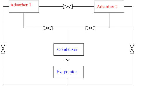
Since the adsorber is alternate in its adsorbing and desorbing functions, the cooling is intermittently produced in single bed system hence usually multiple beds are employed for continuously obtaining the cooling effect. Figure 3 indicates a typical multiple bed adsorption refrigeration system having two beds. In the two-bed ARS, the beds are alternately subjected to heating and cooling processes. When one bed is heated, the other one is cooled, and vice versa in the course of desorption and adsorption processes, respectively. The heating and cooling cycles are reversed after the adsorber beds have reached the desired temperature ranges depending on the refrigerant and adsorbent material used.
Figure 3. Adsorption cooling system with two beds [12]
The studies of many researchers in the past shows the effective cold production by adsorption principles under different operating conditions.
Kumar et al. [13] in their study on Silica gel-water adsorption reported that, the system’s vacuum pressure is what causes adsorption cooling to happen. and the system can produce cold with a heat source temperature of the range of 60℃ to 80℃.
Pinto et al. [14] have studied a two-bed Silicagel water based and four bed activated carbon-R134a based adsorption cooling systems. The simulation studies are also made using a lumped parameter simulation model using MATLAB. Under no load condition a temperature of 5.3℃ is obtained in the evaporator with a refrigeration power of about 284 W and a COP of 0.52 for Silicagel-water system and a COP of 0.55 and a refrigeration power of 325 W were predicted by the simulation model. However, the four-bed system was used in three different ways and the lowest values of temperatures observed were 14.5℃, 13.3℃ and 11.9℃ respectively for no-load conditions with COP values of 0.5, 0.65 and 0.70 and reported that there is a similarity between the simulation and experimental results.
Using silica gel and water, Begum et al. [15] has made an investigation to get 7℃ of fixed chilled water outlet temperature with a two bed type chiller and reported that, the cycle time of 1100 seconds with 38.64 m2 collector area gives better performance with 7℃ with a COP of the cycle as 0.5.
Xia et al. [16] at Shanghai Jiao Tong University studied a silica gel-water ARS driven with a hot water of 60–90℃ and obtained a chilled water of 12℃, COP of 0.39 with the hot and cold water at 82.5℃ and 30.4℃.
In an experimental study by Chen et al. [17] on silicagel-water adsorption chiller, with 82℃ of driving temperature and 12.3℃ of chilled water outlet temperature, 9.60 kW of cooling power and a COP of 0.49 were obtained.
A twin bed mobile adsorption air conditioner was developed by Vasta et al. [18] with zeolite/water pair and obtained a COP of 0.4 and SCP of 600 W/kg.
Using zeolite and water pair, an adsorption system for air conditioning applications was studied by Zhang [19] where the bus's exhaust gases were used to regenerate the adsorption beds and respectively the C.O.P and SCP obtained were 0.38 and 25.7 W/kg.
Wang et al. [20] in their study on adsorption system used solidified activated carbon and methanol combination and achieved a COP of 0.125 and SCP of 16 W/kg for 56 minutes of cycle time.
Khattab [21] have studied a solar adsorption system suitable for Egyptian climatic conditions using activated carbon and methanol for a period of one year for different adsorbent bed’s inclination with sun and achieved a net COP of 0.159 and 0.136 in June and November respectively. The study also revealed that the domestic charcoal has a higher COP than activated charcoal as an adsorbent.
Purnomo and Astina [22] have designed a continuous cooling system to obtain higher cooling capacity by choosing the refrigerant as R-134a. Through transient modelling using CFD software, the cooling power evaluated was 18.36 W, whereas the COP was 0.1047 for the application of ice-making.
Using two adsorption beds, Astinaa et al. [23] have carried out an experimental work using ethanol-activated carbon pair. The results indicated that more COP was produced with hot water temperatures of 100℃ and cold water temperatures of 30℃ than under other conditions. For an operating cycle, the cooling capacity produced was 23.61 kJ and the adsorption bed had a desorption temperature of 85℃, a desorption pressure of 85.52 kPa and a heating time of 80 minutes.
Tashtoush et al. [24] have made an experimental study using methanol as refrigerant with varieties of activated carbon originated from Coconut, Charcoal and Palm seeds. By considering the time interval and type of activated carbon as factors, the factorial analysis was done and the study reported that, the activated carbon derived from coconut shell possess the highest COP of 0.25.
In one of the studies by Utage et al. [25], solar adsorption system was studies using activated charcoal-methanol pair. For effective solar heating and to achieve a generator temperature of up to 114℃, polycarbonate glass was used. According to this study, 6 kg of water could cool at temperatures up to 11℃ with a COP of 0.02.
Habib AND Saha [26] have built a simulation software for modelling and assessing the performance of solar powered adsorption cooling by using the meteorological data of Kaula lampur, Malaysia. They used activated carbon fiber-ethanol pair. The results indicated that the adsorption chiller is practical even with a low temperature source of heat, and with a temperature of roughly 85℃, a cooling capacity of 12 kW was achieved.
In a simulation study by Ramji et al. [27], three types of refrigerants, namely methanol, ammonia and water were used with activated carbon and the results of simulation showed that the cooling achieved by activated carbon-water pair was the best in comparison to other tested pairs. The COP of 0.37 and 0.4 was obtained respectively for methanol and ammonia. Activated carbon-water pair was able to produce an average chilled water outlet temperature of 12℃ with a COP of 0.58.
Using activated carbon and methanol, a solar–powered adsorption based freezing unit was investigated by Hassan [28] under Egypt’s weather conditions. The cooling system was simulated using a dynamic simulation model by taking the actual variation of ambient temperature, solar radiation and wind speed. A flat plate solar collector of 2m×1m was used to power the system and it was reported that the system had a COP of 0.618 and could make 27.82 kg of ice per day at a temperature of -5℃ from water that had a temperature of 25℃.
A Computational Fluid Dynamics (CFD) model was developed by Khanam et al. [29] to assess the performance of a finned tube type adsorber utilising a pair of activated carbon and ethanol. The operating temperatures of the cooling system were 80℃, 20℃ and 15℃ for heating, cooling and evaporation respectively. The temperature profiles from the simulation for different thicknesses of adsorbent were validated with that of experimental data. The analysed SCP and COP were determined to be 488 W/kg and 0.61 respectively, while the ideal cycle time was found to be 800s.
Pongtornkulpanich [30] used a pair of activated carbon and methanol and developed a dynamic simulation programme with solid adsorption cooling and studied the impact of variations in solar radiation intensity on pressure, temperature of the adsorber, and adsorption ratio at each stage of the system's operation, which ranged from 6:00 am on one day to 6:00 am on the other. The simulation's output revealed a COP of 0.43 on average every month.
The influence of hot water, cooling water, chilled water, and cycle time on the COP, SCP, cycled mass, evaporator outlet temperature, and system efficiency is examined in a computational study by Ghilen et al. [31] with silica gel-water pair with mass recovery. With an 85℃ of driving source temperature, the simulation's results showed a COP of 0.7 and SCP of 400 W/kg. The most ideal adsorption-desorption cycle time was discovered to be around 1240s.
Baiju et al. [32] proposed a SIMULINK platform-based transient model of a two-bed ARS. Studies have been done to understand the impact of inlet temperature of chilled water to the evaporator, hot and cooling water temperature to the adsorbent bed on COP, SCP, and refrigeration effect. According to the study's findings, the simulation platform is useful for estimating the output temperatures of system components, and a COP of 0.57 was noted with hot water at 80℃. The outcomes also showed that the system's performance is greatly influenced by the cooling water and hot water inlet temperatures.
Gado et al. [33] developed a mathematical model to increase the cooling power of an adsorption chiller using silica gel/water pair and validated it with experimental data from the literature to forecast the ideal cycle time for a variety of hot, cooling, and chilled water inlet temperatures. At various operating conditions, the performances of an optimal and conventional chiller were compared. With constant hot and chilled water inlet temperatures of 85℃ and 14℃, respectively, the system's cooling capacity tripled when the cooling water's temperature rose from 25℃ to 40℃.
Using activated carbon-ethanol pair, Sha and Baiju [34] have provided a thermodynamic model for analysing the performance of a two-bed solar ARS. For the current study, a 500 W adsorption chiller operating at 5℃ for the evaporator and 45℃ for the condenser was chosen. Evaporator and condenser pressures in the system are 2.01 kPa and 23.1 kPa, respectively. The highest COP of 0.68 was recorded at 95℃ of desorption temperature. Additionally, it was said that the isothermal adsorption process improved the thermal efficiency of the adsorption chiller. It is estimated that the isothermal adsorption system's coefficient of performance (COP) was 13.23% higher than that of traditional isobaric adsorption.
Review of literature shows that there is a need for alternate refrigeration system and adsorption cooling technology is a feasible solution which can overcome the drawbacks of VCR and absorption systems. There are both experimental and theoretical studies on ARS with different working pairs, operating variables and heat sources. The results obtained for different working pairs are different under different operating environments. The Studies on adsorption systems based on activated carbon are significant in comparison with silica gel based systems. The literature also shows that the COP of adsorption systems are low compare to conventional systems and there is a need to improve the performance. Additionally, it is evident that there has been comparatively little research on adsorption refrigeration systems in India. Our present work focuses on experimental and simulation studies on two bed adsorption refrigeration system to produce cooling effect by using heat input partly obtained from solar energy.
In the present work the source of heat to achieve desorption process is the hot water drawn from evacuated tube solar collectors as shown in Figure 4. There are two collectors each having a water tank of capacity 500 liters each totally amounting to 1000 liters. Each collector contains 30 evacuated collecting tubes, each measuring 68 inches in length and 60 mm in outer diameter. Also an electric heater of 1500W capacity is employed to partially heat the water to the desirable value of temperature if the hot water from the solar system is not at the expected desorption temperature.
Figure 4. Evacuated tube solar water heaters
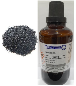
Granular form of activated carbon and Methanol are employed as adsorbent and adsorbate pair in the current work which is shown in Figure 5. Table 2 shows the particle aggregation characteristics of activated carbon as provided by suppliers (NICE Chemicals). This pair is chosen because activated carbon possess high porosity and adsorption capacity of methanol on it is good and for this pair, desorption can be achieved at lower range of temperature.
Figure 5. Activated carbon granules and methanol
Table 2. Properties of granular activated carbon
|
Property |
Value |
|
Sublimation point |
3700℃ |
|
Density at 20℃ |
2 g/cm3 |
|
Bulk Density |
400 kg/m3 |
|
Solubility in water at 20℃ |
Insoluble |
|
Particle size |
Near 1.5 mm |
|
pH Value |
6.5-7.5 |
|
Hydrochloric acid soluble matter |
5% max |
2.1 Experimental details
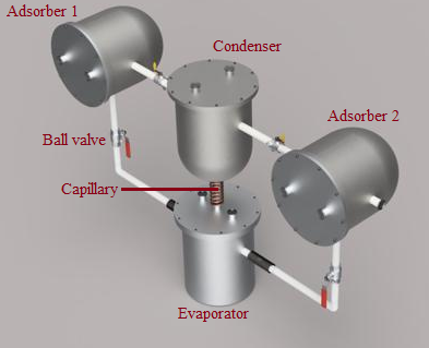
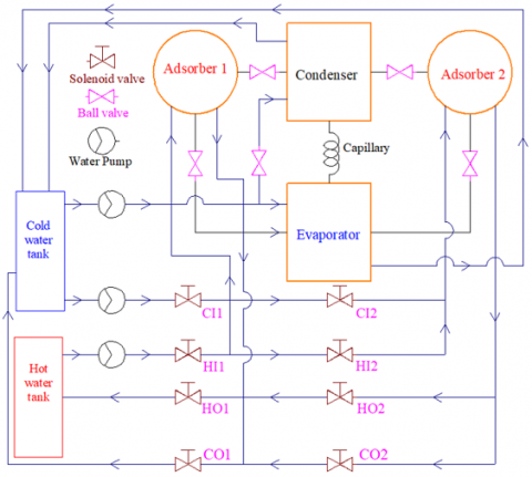
Figures 6 and 7 depict the 3D model and photograph of the two bed ARS used in the current study. A finned tube heat exchanger bed with adsorbent packing that is a component of ARS is found inside the adsorber vessel. By circulating hot or cold water, the bed can be heated or cooled. Without any adsorbent packing, the condenser resembles an adsorbent bed. A refrigerant-filled vessel called an evaporator is subjected to cooling during the operation. The water can be circulated via a heat exchanger coil that is submerged in the refrigerant and has its ends exposed to the outside to take away this cooling effect. Figure 8 shows the layout of the double bed adsorption Refrigeration system test setup Where CI1, CO1, CI2, CO2, HI1, HO1, HI2, HO2 depicts the control valves that control the water's flow to the adsorber beds. The first letter C or H represent either cold or hot. The second letter I or O designates water flow at the inlet or outlet. The adsorber bed is indicated by the number 1 or 2.
Figure 6. 3D model showing the assembly of vessels
Figure 7. Picture of the two bed adsorption refrigeration test setup
Figure 8. Layout showing the double or twin bed adsorption Refrigeration system
2.2 Experimental procedure
A known mass of refrigerant is added to the evaporator, and the system is then evacuated. For the desired amount of time, hot and cold water circulation is used to alternately subject the adsorber beds to adsorption and desorption. Desorbed refrigerant vapor gets condensed in the condenser. After a particular span of time, one bed is subjected to desorption and other bed is subjected to adsorption. The same procedure is repeated.
If the cold produced in the evaporator is not taken away, the evaporator attains its lowest temperature, which is referred to as a "no-load condition," during which no refrigeration power is produced. Refrigeration power is produced if the system is put under an external heat load by circulating the water via evaporator coil where the water decreases in its temperature by taking away the cooling effect produced in the evaporator and this is called load condition [14]. Pumps and control valves are provided in the circuit at different places to circulate the hot and cold fluids as desired. Using a vacuum pump, the system is evacuated at regular intervals. and temperatures and pressures are noted at different places during the operation.
The following section shows the lumped parameter simulation model established for predicting the performance of ARS. The assumptions made in the model are as follows [14, 32, 33].
(1) In the adsorber beds, the pressure, temperature and the quantity of methanol adsorbed are uniform.
(2) No heat loss from the beds as they are insulated.
(3) The vapour refrigerant is regarded as an ideal gas while the adorbed phase is considered as a liquid.
(4) The thermal properties are constant with temperature for all metallic components.
(5) The power consumption for pumping fluids are neglected.
The heat and mass transfer inside the various components of ARS may now be expressed mathematically as follows.
3.1 Equilibrium uptake (Adsorption isotherm)
In the current chiller model, Dubinin-Astakhov (D−A) equation [35] is used to estimate the uptake of Methanol for Activated carbon- Methanol pair. It describes how much refrigerant is present in the adsorbent's pores.
$X=X_0 \exp \left[-D\left[T \ln \frac{P_{s a t}\left(T_{a d s}\right)}{P_{s a t}\left(T_{\text {ref }}\right)}\right]^{(n)}\right]$ (1)
where, X represents the amount of methanol adsorbed in the bed at temperature T for adsorption, X0 is the maximum or saturated adsorption capacity, Psat(Tref) and Psat(Tads) are the saturation vapour pressures (in Pa) of the refrigerant at the evaporator and the adsorber bed temperatures. The values of the coefficients are discussed in the study [36] and are taken as X0=0.45, D=9.08×10⁻⁶ and n=1.50. These values vary with different working pairs. The linear driving force (LDF) equation [34] determines the rate of adsorption or desorption in an adsorbent bed and can be written as:
$\frac{d x}{d t}=k_{a d s / d e s}(X-x)$ (2)
kads/des is the overall mass transfer coefficient, given by:
$k_{a d s / d e s}=\frac{15 D_{s o}}{R_p^2} \exp \left(-\frac{E_a}{R_u T_{a d s}}\right)$ (3)
The values 15Ds0/Rp2 and Ea/Ru were taken from the study [37] as 15Ds0/Rp2=7.35×10-3s-1; Ea/Ru=978 K.
In the above equation, X is the equilibrium uptake (Methanol concentration on activated carbon) and x is the instantaneous uptake at a given time.
3.2 Energy balance equations
The following section discusses the equations of energy balance for the various components of ARS. The equations are written by taking into account the mechanism of heat transfer occurs inside the components and based on the similar studies made by Pinto et al. [14], Khanam et al. [29], Baiju et al. [32], Gado et al. [33], Passos et al. [37], Sakoda and Suzuki [38], and so on.
3.3 Adsorber bed modeling
The precooling process makes it possible for adsorption by lowering the bed's pressure from the condenser to the evaporator. The energy balance can be expressed as follows during precooling of the adsorber bed:
$\begin{align} & \frac{d}{dt}\left[ \left( \mathop{M}_{a}\mathop{C}_{pads\,\,}+\mathop{M}_{a}\mathop{C}_{pref\,\,\,}\,x+\,\mathop{M}_{abed}\mathop{C}_{pabed\,\,} \right)\mathop{T}_{ads} \right] =\mathop{m}_{acw\,\,}\mathop{C}_{pw\,\,\,}\left( \mathop{T}_{acin\,}-\mathop{T}_{acout\,} \right) \\ \end{align}$ (4)
Energy balance during the adsorption can be written as:
$\begin{align} & \frac{d}{dt}\left[ \left( \mathop{M}_{a}\mathop{C}_{pads\,\,}+\mathop{M}_{a}\mathop{C}_{pref\,\,\,}\,x+\,\mathop{M}_{abed}\mathop{C}_{pabed\,\,} \right)\mathop{T}_{ads} \right] =\mathop{M}_{a}\mathop{q}_{st\,\,}\frac{\mathop{dx}_{ads}}{dt}\,+\mathop{m}_{acw\,\,}\mathop{C}_{pw\,\,\,}\left( \mathop{T}_{acin\,}-\mathop{T}_{acout\,} \right)\,+ \mathop{M}_{a}\mathop{C}_{prefv\,\,\,}\frac{\mathop{dx}_{ads}}{dt}\left( \mathop{T}_{eva\,}-\mathop{T}_{ads\,} \right) \\ \end{align}$ (5)
The cooling water outlet temperature during the precooling and adsorption can be written as:
$T_{\text {acout }}=T_{a d s}+\left(T_{a c i n}-T_{a d s}\right) \exp \left(\frac{-(U A)_{a d s}}{m_{c a d s} C_{p w}}\right)$ (6)
Energy balance during the preheating of the adsorber bed can be taken as:
$\begin{align} & \frac{d}{dt}\left[ \left( \mathop{M}_{a}\mathop{C}_{pads\,\,}+\mathop{M}_{a}\mathop{C}_{pref\,\,\,}\,x+\,\mathop{M}_{abed}\mathop{C}_{pabed\,\,} \right)\mathop{T}_{ads} \right] =\mathop{m}_{ahw\,\,}\mathop{C}_{pw\,\,\,}\left( \mathop{T}_{ahin\,}-\mathop{T}_{ahout\,} \right) \\ \end{align}$ (7)
Energy balance during desorption can be written as:
$\begin{aligned} & \frac{d}{d t}\left[\left(M_a C_{\text {pads }}+M_a C_{\text {pref }} x+M_{\text {abed }} C_{\text {pabed }}\right) T_{\text {ads }}\right] \quad=M_a q_{s t} \frac{d x_{\text {des }}}{d t}+m_{a h w} C_{p w}\left(T_{\text {ahin }}-T_{\text {ahout }}\right)\end{aligned}$ (8)
During preheating and desorption, the outlet temperature of hot water may be expressed as:
$T_{\text {ahout }}=T_{\text {des }}+\left(T_{\text {ahin }}-T_{\text {des }}\right) \exp \left(\frac{-(U A)_{\text {des }}}{m_{\text {ahw }} C_{p w}}\right)$ (9)
3.4 Modelling of the condenser
The following is a possible representation of the condenser's energy balance during adsorption and desorption:
$\begin{aligned} & \frac{d}{d t}\left[\left(M_{c o n} C_{p c u}\right) T_{c o n}\right]+M_a C_{\text {prefv}} \frac{d x_{d e s}}{d t}\left(T_{d e s}-T_{c o n}\right) { }^{+} M_a h_{f g} \frac{d x_{d e s}}{d t}=m_{c c w} C_{p w}\left(T_{c c i n}-T_{\text {ccout }}\right)\end{aligned}$ (10)
While precooling / preheating, the energy balance for the condenser can be shown as:
$\frac{d}{d t}\left[\left(M_{\text {con }} C_{p c u}\right) T_{\text {con }}\right]=m_{c c w} C_{p w}\left(T_{\text {ccin }}-T_{\text {ccout }}\right)$ (11)
The condenser outlet temperature during desorption and precooling can be taken as:
$T_{\text {ccout }}=T_{\text {con }}+\left(T_{c c i n}-T_{\text {con }}\right) \exp \left(\frac{-(U A)_{c o n}}{m_{\text {ccon }} C_{p w}}\right)$ (12)
3.5 Evaporator modelling
During adsorption / desorption, the energy balance equation for the evaporator can be taken as:
$\begin{align} & \frac{d}{dt}\left[ \left( \mathop{M}_{eva}\mathop{C}_{peva\,\,}+\mathop{M}_{refeva}\mathop{C}_{pref\,\,\,}\, \right)\mathop{T}_{eva} \right] =\mathop{M}_{a}\mathop{h}_{fg\,\,}\frac{\mathop{dx}_{ads}}{dt}\,=\mathop{m}_{chill\,\,}\mathop{C}_{pw\,\,\,}\left( \mathop{T}_{chillin\,}-\mathop{T}_{chillout\,} \right)\, \\ \end{align}$ (13)
The energy balance for the evaporator while precooling / preheating can be written as:
$\begin{aligned} & \frac{d}{d t}\left[\left(M_{\text {eva }} C_{\text {peva }}+M_{\text {refeva }} C_{\text {pref }}\right) T_{\text {eva }}\right] =m_{\text {chill }} C_{p w}\left(T_{\text {chillin }}-T_{\text {chillout }}\right)\end{aligned}$ (14)
The chilled water outlet temperature during adsorption and preheating can be expressed as:
$T_{\text {chillout }}=T_{\text {eva }}+\left(T_{\text {chillin }}-T_{\text {eva }}\right) \exp \left(\frac{-(U A)_{\text {eva }}}{m_{\text {chill }} C_{p w}}\right)$ (15)
3.6 Conservation of mass
The rate of variation of mass of the refrigerant (Methanol) is the same as the amount of desorbed refrigerant during the desorption time as well as the amount of refrigerant adsorbed during the adsorption process.
$\frac{d M_{\text {refeva }}}{d t}=-M_a\left(\frac{d x_{a d s}}{d t}+\frac{d x_{d e s}}{d t}\right)$ (16)
3.7 System performance evaluation
The performance of ARS is assessed by Coefficient of performance which can be expressed as:
$C O P=\frac{Q_e}{Q_h}$ (17)
$Q_e=\frac{m_{\text {chill }} C_{p w}}{t_{\text {cycle }}} \int_0^{t_{\text {cycle }}}\left(T_{\text {Chillin }}-T_{\text {Chillout }}\right) d t$ (18)
$Q_h=\frac{m_{a h w} C_{p w}}{t_{c y c l e}} \int_0^{t_{c y c l e}}\left(T_{a h i n}-T_{a h o u t}\right) d t$ (19)
The equations containing the lumped parameters are solved numerically with finite difference approach with 1 second time step. To analyze the dynamic behavior of adsorption cooling system, a simulation code is written using MATLAB. For the simulation study, the values used are listed in Table 3.
Table 3. Values adopted for simulation [14]
|
Parameter |
Values |
Unit |
|
hfg |
1102 |
KJ/kg |
|
qst |
1900 |
KJ/kg |
|
UAads |
125 |
W/k |
|
UAdes |
105 |
W/k |
|
UAeva |
120 |
W/k |
|
UAcond |
450 |
W/k |
|
Ma |
10 |
Kg |
|
Cprefl |
2.53 |
KJ/kg ℃ |
|
Cprefv |
1.370 |
KJ/kg ℃ |
|
Cpads |
0.71 |
KJ/kg ℃ |
|
Cpcu |
0.387 |
KJ/kg ℃ |
|
Cpeva |
0.387 |
KJ/kg ℃ |
|
Cpabed |
0.593 |
KJ/kg ℃ |
|
mccw |
0.05 |
kg/s |
|
mahw |
0.025 |
kg/s |
|
macw |
0.05 |
kg/s |
It is clear from Eqns. (1) to (19) that different parameters affect the performance of the ARS. The parameters which mainly affect the performance are inlet temperature and mass flow rates of hot as well as cold water and adsorption/desorption time. Based on these input parameters the temperature profiles pertaining to the different components of ARS are studied and the same are compared with the temperature profiles drawn from the experiment.
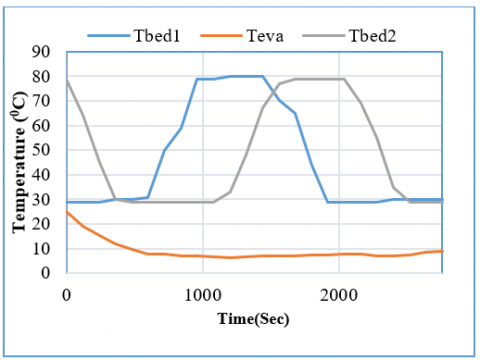
The experimental and simulated temperature profiles are shown in Figures 9 and 10. This indicates the present model prediction much agrees with experimental data for same base line physical parameters considered.
Figure 9. Experimental temperature profiles for adsorber 1, 2 and evaporator
Figure 10. Simulated temperature profiles for adsorber 1, 2 and evaporator
The validation of experimental results with simulation results for Activated Carbon-Methanol is shown as follows:
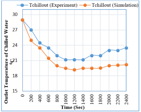
Figure 11. Chilled water outlet temperature v/s time with load
The Figure 11 indicates the simulated and experimentally measured outlet chilled water temperature from the evaporator for Activated Carbon-Methanol pair. It can be observed that current prediction much agrees with experimental data. The predicted cooling capacity for Activated Carbon-Methanol pair is 280 W while the experimental cooling capacity is 250 W. This deviation is because of heat loss from/to the system. Also as the time progresses, the increase of deviation of experimental and simulation results are observed because of the decrease of the adsorption rate and hence the cooling effect due to the saturation of the adsorbent bed with the vapors of adsorbate.
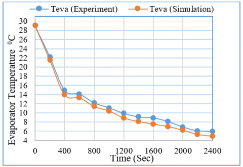
Figure 12 compares the experimental and simulated data for Activated Carbon-Methanol combination in the evaporator without load. It is observed that the simulated evaporator temperature profile much agrees with experimentally measured temperatures. In addition to that, simulation model predicts the same behaviour compared to experimental data. Under no load condition, the temperature of 6℃ is produced in the evaporator however, the simulation model gives a value of 4.9℃.
Figure 12. Evaporator temperature v/s time without load
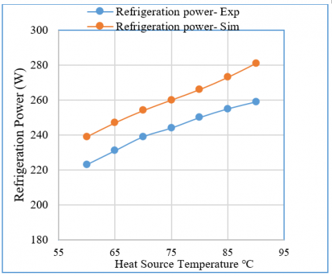
Figure 13 reveals that, as the heat source’s (hot water) temperature increases, the refrigeration power also increases due to the effective desorption which drives more refrigerant vapors into the evaporator. The deviation b/w the experimental and simulated result is because of the heat loss [13].
Figure 13. Variation of refrigeration power with heat source temperature
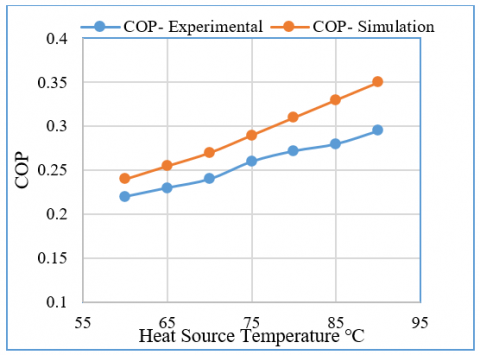
Figure 14 shows how driving temperature affects coefficient of performance (COP). It reveals that, higher the driving temperature, higher is the value of COP because at higher temperatures, better desorption occurs in the adsorbent beds. Also the simulated and the experimental values are comparable and having close relationship.
Figure 14. Variation of COP with heat source temperature
The two-bed adsorption refrigeration system studied is successful in producing the cooling effect with activated carbon and methanol as working pair using hot water as the source of heat input which is obtained with the aid of solar energy. The lumped parameter simulation model is able to foresee the temperature profiles and refrigeration power values successfully and the present model prediction much agrees with experimental data. A no load temperature of 6℃ is observed in the evaporator during the experiment and the value obtained from the simulation model is 4.9℃. The cooling power and COP obtained from the experiment and the simulation amounts to 250 W, 0.29 and 280 W, 0.35 respectively. For the chosen working pair the system should be operated under vacuum and maintaining the same for long time is difficult. In the present work, since the ARS is integrated with solar water heating system, the usage of electricity for producing refrigeration is greatly reduced. The market potential in future is high for solar and renewable energy based adsorption systems since the current refrigeration industries are aiming to reduce carbon emission. Based on the findings of this study, it can be concluded that, adsorption cooling systems may replace traditional cooling methods in ways that lessen both global warming and ozone layer destruction. Analytical works can be extended further to optimize the process variables for the enhanced cooling performance and the plans are being made to develop the system components with effective design to make the adsorption chillers as commercially marketable systems in the near future.
|
A |
Area, m2 |
|
ARS |
Adsorption Refrigeration System |
|
COP |
Coefficient of performance |
|
Cpabed |
Specific heat of adsorbent bed heat exchanger, kJ/kg.K |
|
Cpads |
Specific heat of adsorbent, kJ/kg.K |
|
Cpcu |
Specific heat of condenser heat exchanger, kJ/kg.K |
|
Cpeva |
Specific heat of evaporator heat exchanger, kJ/kg.K |
|
Cpref |
Specific heat of Refrigerant, kJ/kg.K |
|
Cprefv |
Specific heat of Refrigerant Vapour, kJ/kg.K |
|
Cpw |
Specific heat of water, kJ/kg.K |
|
Dso |
Pre-exponential constant in the kinetics equation, m2/s |
|
Ea |
Activation energy of surface diffusion, kJ/kg |
|
hfg |
Latent heat of vaporization, KJ kg-1 |
|
Ma |
Mass of adsorbent, kg |
|
Mabed |
Mass of adsorbent bed heat exchanger, kg |
|
macw |
Cold water flow rate to adsorbent bed, kg/s |
|
mahw |
Hot water flow rate to adsorbent bed, kg/s |
|
Matotal |
Total mass of adsorbent in the chiller, kg |
|
mccw |
Cold water flow rate to condenser, kg/s |
|
mchill |
Chilled water flow rate to evaporator, kg/s |
|
Mcon |
Mass of heat exchanger of condenser, kg |
|
Meva |
Mass of heat exchanger of evaporator, kg |
|
Mrefeva |
Mass of refrigerant in the evaporator, kg |
|
Qe |
cooling power, W |
|
Qh |
heat input, W |
|
qst |
Isosteric heat of adsorption, kJ /kg |
|
Rp |
Average radius of Activated carbon particle, m |
|
Ru |
Universal gas constant, kJ/kg.K |
|
Tacin |
Inlet temperature of cold water to adsorbent bed, ℃ |
|
Tacout |
Outlet temperature of cold water to adsorbent bed, ℃ |
|
Tads |
Adsorbent bed temperature at adsorption mode, ℃ |
|
Tccin |
water inlet temperature to condenser, ℃ |
|
Tccout |
water outlet temperature to condenser, ℃ |
|
Tchillin |
Chilled water inlet temperature to evaporator, ℃ |
|
Tchillout |
Chilled water outlet temperature to evaporator, ℃ |
|
Tcon |
Condenser Temperature, ℃ |
|
tcycle |
Cycle time, s |
|
Tdes |
Adsorbent bed temperature at desorption mode, ℃ |
|
Teva |
Evaporator Temperature, ℃ |
|
U |
Ovrall heat transfer coefficient, W/m2K |
|
UAads |
Overall conductance of adsorber bed during adsorption, W/K |
|
UAcon |
Overall conductance of condenser, W/K |
|
UAdes |
Overall conductance of adsorber bed during desorption, W/K |
|
UAeva |
Overall conductance of evaporator heat exchanger, W/K |
|
x or x |
Instantaneous uptake, kg/kg of adsorbent |
|
X |
Concentration of Methanol on Activated carbon, kg/kg of adsorbent |
|
X0 |
Maximum Adsorption capacity, kg/kg of adsorbent |
|
Xads |
Adsorption uptake, kg/kg of adsorbent |
|
Xdes |
Desorption quantity, kg/kg of adsorbent |
|
Subscripts |
|
|
ads |
adsorption/adsorber |
|
chill |
chilled water |
|
cond |
condenser |
|
cw |
Cooling water |
|
des |
Desorption/desorber |
|
eva |
evaporator |
|
hw |
Hot water |
|
in |
inlet |
|
out |
outlet |
|
ref |
Refrigerant |
[1] International Energy Outlook. (2021). U.S. Energy Information Administration, Department of Energy, Washington, 2021. https://www.eia.gov/outlooks/ieo/.
[2] Fan, Y., Luo, L., Souyri, B. (2007). Review of solar sorption refrigeration technologies: Development and applications. Renewable and Sustainable Energy Reviews, 11(8): 1758-1775. https://doi.org/10.1016/j.rser.2006.01.007
[3] IEA. (2018). Percentage of households equipped with AC in selected countries, IEA, Paris. https://www.iea.org.
[4] Kumar, A., Kapilan, N., Kasthurirengan, S. (2021). Performance studies on solar assisted single and double bed adsorption refrigeration system. Nveo-Natural Volatiles & Essential Oils Journal| NVEO, 10594-10610. https://www.nveo.org/index.php/journal/article/view/2984.
[5] Ogueke, N.V., Ndeke, C., Anyanwu, E.E. (2014). Exergy based performance analysis of a solid adsorption solar refrigerator. International Journal of Renewable Energy Research, 4(2): 363-370. https://doi.org/10.1234/IJRER.V4I2.1198.G6288
[6] Srivastava, D. (2017). Adsorption refrigeration using zeolite-water pair on pro-e and MATLAB. International Journal of Advance Research, Ideas and Innovations in Technology, 3(4): 599-613.
[7] Kadam, Y.H., Yadav, D.H., Mohite, S.J., Panchal, P.P., Dongare, V.K. (2016). Design of waste heat driven vapour adsorption cooling system for vehicle air-conditioning and refrigeration. International Journal of Research in Engineering and Technology, 5(04): 89-93. https://doi.org/10.15623/IJRET.2016.0504018
[8] Wang, L.W., Wang, R.Z., Oliveira, R.G. (2009). A review on adsorption working pairs for refrigeration. Renewable and Sustainable Energy Reviews, 13(3): 518-534. https://doi.org/10.1016/j.rser.2007.12.002
[9] Shabir, F., Sultan, M., Miyazaki, T., Saha, B.B., Askalany, A., Ali, I., Zhou, Y., Ahmad, R., Shamshiri, R.R. (2020). Recent updates on the adsorption capacities of adsorbent-adsorbate pairs for heat transformation applications. Renewable and Sustainable Energy Reviews, 119: 109630. https://doi.org/10.1016/j.rser.2019.109630
[10] Kumar, K.A., Kapilan, N. (2020). Studies on the feasibility of adsorption cooling technologies. In Journal of Physics: Conference Series, 1473(1): 012050. https://doi.org/10.1088/1742-6596/1473/1/012050
[11] Manmode, B.K., Aher, B.B. (2018). Review on adsorption refrigeration system. IOSR Journal of Mechanical and Civil Engineering, 1-4.
[12] Kumar, K.A., Kapilan, N. (2021). Studies on the feasibility of adsorption cooling technologies–A review. In AIP Conference Proceedings, 2316(1): 030019. https://doi.org/10.1063/5.0036432
[13] Kumar, D.D., Karshna, S.A., Kasthurirengan, S., Krishnappa, G.B. (2016). An experimental investigation on adsorption refrigeration system using silica gel-water. Journal of Mechanical Engineering and Biomechanics, 1(1): 56-63.
[14] Pinto, S.P., Karanam, P., Raghavendra, B.G., Boopathi, V., Mathad, P., Behera, U., Kasthurirengan, S. (2019). Development and studies of low capacity adsorption refrigeration systems based on silica gel-water and activated carbon-R134a pairs. Heat and Mass Transfer, 55: 513-531. https://doi.org/10.1007/s00231-018-2441-0
[15] Begum, F.A., Khan, M.Z.I., Rouf, R.A., Alam, K.C.A. (2018). Effect of flow rate on performance of solar adsorption chiller keeping fixed evaporator outlet temperature. Journal of Applied uoJ Mechanical Engineering, 7(4): 310. https://doi.org/10.4172/2168-9873.1000310
[16] Xia, Z.Z., Wang, R.Z., Wang, D.C., Liu, Y.L., Wu, J.Y., Chen, C.J. (2009). Development and comparison of two-bed silica gel–water adsorption chillers driven by low-grade heat source. International Journal of Thermal Sciences, 48(5): 1017-1025. https://doi.org/10.1016/j.ijthermalsci.2008.07.004
[17] Chen, C.J., Wang, R.Z., Xia, Z.Z., Kiplagat, J.K., Lu, Z.S. (2010). Study on a compact silica gel–water adsorption chiller without vacuum valves: design and experimental study. Applied Energy, 87(8): 2673-2681. https://doi.org/10.1016/j.apenergy.2010.03.022
[18] Vasta, S., Freni, A., Sapienza, A., Costa, F., Restuccia, G. (2012). Development and lab-test of a mobile adsorption air-conditioner. International Journal of Refrigeration, 35(3): 701-708. https://doi.org/10.1016/j.ijrefrig.2011.03.013
[19] Zhang, L.Z. (2000). Design and testing of an automobile waste heat adsorption cooling system. Applied Thermal Engineering, 20(1): 103-114. https://doi.org/10.1016/S1359-4311(99)00009-5
[20] Wang, L.W., Wu, J.Y., Wang, R.Z., Xu, Y.X., Wang, S.G., Li, X.R. (2003). Study of the performance of activated carbon–methanol adsorption systems concerning heat and mass transfer. Applied Thermal Engineering, 23(13): 1605-1617. https://doi.org/10.1016/S1359-4311(03)00104-2
[21] Khattab, N.M. (2004). A novel solar-powered adsorption refrigeration module. Applied Thermal Engineering, 24(17-18): 2747-2760. https://doi.org/10.1016/j.applthermaleng.2004.04.001
[22] Purnomo, D.M.J., Astina, I.M. (2016). Continuous adsorption refrigeration performance of activated Carbon–R134a pair for Ice-Making application using transient CFD simulation. ASEAN Engineering Journal, 6(2): 36-45. https://doi.org/10.11113/aej.v6.15482
[23] Astina, I.M., Sokha, R., Darmanto, P.S. (2017). Study on adsorption refrigeration system using activated carbon–ethanol as working pair. Int. J. of Thermal & Environmental Engineering, 15(2): 143-150. https://doi.org/10.5383/ijtee.15.02.010
[24] Tashtoush, G.M., Tashtoush, B.M., Jaradat, M.M. (2012). Experimental study of a solar adsorption refrigeration unit, factorial analysis. Smart Grid and Renewable Energy, 3(2): 126-132. http://dx.doi.org/10.4236/sgre.2012.32018
[25] Utage, A.S., Nadgire, A.R., Yadav, R.J., Patane, P.M., Lele, M.M. (2017). Experimental investigation of solar adsorption refrigeration system using activated charcoal-methanol working pair. International Journal of Current Engineering and Technology, 7: 393-397.
[26] Habib, K., Saha, B.B. (2013). performance evaluation of solar driven activated carbon fiber-ethanol based adsorption cooling system in Malaysia. Asian Journal of Scientific Research, 6(2): 146-156. https://doi.org/10.3923/ajsr.2013.146.156
[27] Ramji, H.R., Leo, S.L., Tan, I.A.W., Abdullah, M.O. (2014). Comparative study of three different adsorbent-adsorbate working pairs for a waste heat driven adsorption air conditioning system based on simulation. International Journal of Recent Research and Applied Studies, 18(2): 109-121.
[28] Hassan, H.Z. (2013). A solar powered adsorption freezer: A case study for Egypt’s climate. International Journal of Energy Engineering, 3(1): 21-29. https://doi.org/10.5923/j.ijee.20130301.04
[29] Khanam, M., Jribi, S., Miyazaki, T., Saha, B.B., Koyama, S. (2018). Numerical investigation of small-scale adsorption cooling system performance employing activated carbon-ethanol pair. Energies, 11(6): 1499. https://doi.org/10.3390/en11061499
[30] Pongtornkulpanich, A. (2014). Dynamic simulation of solid adsorption solar refrigerator system with AC/CH3OH as a working pair. Energy and Power Engineering, 6(12): 459-465. http://dx.doi.org/10.4236/epe.2014.612038
[31] Ghilen, N., Gabsi, S., Benelmir, R., El Ganaoui, M. (2017). Performance simulation of two-bed adsorption refrigeration chiller with mass recovery. Journal of Fundamentals of Renewable Energy and Applications, 7(3): 1-7. http://dx.doi.org/10.4172/2090-4541.1000229
[32] Baiju, V., Asif Sha, A., Sajid, N.M., Muhammedali Shafeeque, K. (2022). Simulation and performance study of a two-bed adsorption cooling system operated with activated carbon-ethanol. Proceedings of the Institution of Mechanical Engineers, Part C: Journal of Mechanical Engineering Science, 236(7): 3804-3817. https://doi.org/10.1177/09544062211042040
[33] Gado, M., Elgendy, E., Elsayed, K., Fatouh, M. (2019). Performance enhancement of an adsorption chiller by optimum cycle time allocation at different operating conditions. Advances in Mechanical Engineering, 11(10): 1687814019884780. https://doi.org/10.1177/1687814019884780
[34] Sha, A.A., Baiju, V. (2021). Thermodynamic analysis and performance evaluation of activated carbon-ethanol two-bed solar adsorption cooling system. International Journal of Refrigeration, 123: 81-90. https://doi.org/10.1016/j.ijrefrig.2020.12.006
[35] Zhao, Y., Hu, E., Blazewicz, A. (2012). Dynamic modelling of an activated carbon–methanol adsorption refrigeration tube with considerations of interfacial convection and transient pressure process. Applied Energy, 95: 276-284. https://doi.org/10.1016/j.apenergy.2012.02.050
[36] Taylan, O., Baker, D.K., Kaftanoğlu, B. (2010). Adsorbent–Refrigerant comparison for a solar powered adsorption cooling system using seasonal simulations. In Proceedings of 10th REHVA World Congress.
[37] Passos, E.F., Escobedo, J.F., Meunier, F. (1989). Simulation of an intermittent adsorptive solar cooling system. Solar Energy, 42(2): 103-111. https://doi.org/10.1016/0038-092X(89)90137-0
[38] Sakoda, A., Suzuki, M. (1984). Fundamental study on solar powered adsorption cooling system. Journal of Chemical Engineering of Japan, 17(1): 52-57. https://doi.org/10.1252/jcej.17.52