Nuha Khairunnisa | Zainal Arifin* | Budi Kristiawan | Miftah Hijriawan | Singgih Dwi Prasetyo
© 2022 IIETA. This article is published by IIETA and is licensed under the CC BY 4.0 license (http://creativecommons.org/licenses/by/4.0/).
OPEN ACCESS
As the primary basis for electricity production, fossil fuels continue to decline. Solar Photovoltaic (PV) can be developed by utilizing solar energy. However, solar PV has low efficiency due to overheating from solar irradiation. This article analyzed forced convection Sunwatt 50Wp solar PV water cooling to lower the PV temperature and increase efficiency. The heat exchanger uses a spiral and rectangular configuration mounted on the back of the Sunwatt 50Wp solar PV panel with water flow. Sunwatt 50Wp solar PV testing using a solar simulator at an intensity of 470 W/m2, 625 W/m2, 870 W/m2, and 1000 W/m2. The test results show a decreased working temperature on spiral cooling at all intensities compared to solar PV without cooling. This impacts the low-performance value of solar PV without cooling. The intensity of 1000 W/m2 has a high value due to the release of electrons from the atoms in the cell. These results impact increasing electricity efficiency in Sunwatt 50Wp solar PV by cooling. At high intensity, the temperature increases causing the ability to increase efficiency to decrease. However, water cooling can increase electrical efficiency because the particles are evenly distributed in the heat exchanger, which causes a high heat transfer rate.
heat exchanger, solar PV, water cooling, intensity, spiral rectangular tubes
An energy-intensive environment and consumerism have contributed to the rapid decline of fossil fuels, which are the primary basis for electricity production. For 56 years, the average fossil energy consumption in the world has reached 44.47 Twh and will continue to increase yearly [1]. The discovery of new sustainable energy sources continues to be developed to reduce dependence on fossil fuels. This encourages increased use of renewable energy on a large scale, such as solar. Solar is a commonly used non-conventional energy that is available worldwide. Development of the utilization of solar energy as an energy source by utilizing solar irradiation as a source of all types of renewable energy.
The use of solar energy has been developed into two types of technology, namely solar thermal and solar photovoltaic (PV) [2]. Solar irradiation can be converted directly or indirectly into electrical energy through PV or thermal collectors. The primary limits of PV systems are PV efficiency and thermal efficiency. PV efficiency range is 10-20%, while thermal efficiency is 40-60% [3]. The resulting efficiency is a challenge, as it can decrease as the operating temperature increases. An increase in the operating temperature of solar panels can result in overheating due to excessive solar irradiation and high ambient temperatures [4].
This increase in temperature can occur due to the visible wavelength between 380 nm to 700 nm, which solar cells use to produce electricity. The energy required to make an electron-hole pair is insufficient for wavelengths longer than 700 nm [5]. High energy photons are present in shorter wavelength radiation such as X-rays, but they can potentially harm photovoltaic cells through ionization reactions. Unwanted radiant energy from the sun is then converted into heat which can increase the temperature of the solar cell beyond the visible wavelengths [6]. This phenomenon increases the temperature of the PV panel, which impacts decreasing the efficiency of the PV panel performance. Therefore, the temperature of solar panels must be lowered to increase energy efficiency and power [7]. Temperature changes are influenced by environmental parameters such as exposure to solar irradiation, wind speed, humidity, atmospheric temperature, and dust [8].
Cooling systems developed to reduce PV operational temperatures are passive and active cooling [9]. Passive cooling does not require any other mechanical device to circulate the fluid [10, 11]. Active cooling methods involve additional external energy, such as fans and pumps, to circulate wind or water fluids [12]. For this reason, a continuous power source is needed, which has a relatively large ability to cool solar cells [13].
Active cooling has been developed, such as forced air/water, nanofluid, and refrigerant cooling [14]. The water fluid is required to flow through the system with the help of continuous pumping. This water circulation can use solar-powered DC or magnetic pumps [15]. Water is circulated using cooling pipes installed at the top or bottom of the panel to lower the temperature. The waste heat of the PV module resulting from the absorption of excess radiation can then be transferred to the circulating cooler.
Several studies have been conducted to develop cooling systems. Colt circulates water on the back surface using an aluminum radiator as a heat exchanger to extract heat from the photovoltaics. The results show that the photovoltaic surface temperature decreases by 32%, and the electricity efficiency increases by 57% [16]. Kabeel et al. [17] conducted a comparative study of cooling techniques for PV modules with reflectors. Three different cooling techniques, namely forced air, water cooling, and forced air/water cooling combinations were considered in this study. Experimental results show that water cooling is the best option for PV modules under Egyptian climate conditions. Smith M. et al. used several ice cubes filled into a water tank to keep the water temperature as low as possible by flowing water over the surface of the PV panel, which can transfer heat to the water. This results in the temperature of PV panels with a water-cooling system always being lower than that of PV panels without a cooling water system. This proves that the electrical behavior of PV panels can be improved by 4.6% by using a water-cooling system [18]. In addition, Bashir, MA et al. investigated the cooling effect of four pre-cooled and uncooled PV modules. The two modules are modified by creating channels on their rear surface with inlets and outlets for water flow. The average uncooled c-Si and p-Si module temperatures were 13.6% and 7.2% lower than those of the same module without cooling. The average electrical efficiency of the c-Si and p-Si modules is 13% and 6.2% higher, respectively, compared to the uncooled module [3]. Using air as a coolant was found to reduce solar cell temperature by 4.7℃ and increase solar panel efficiency by 2.6%, while using water as a coolant reduced solar cell temperature by 8℃ and panel efficiency by 3%. Therefore, water cooling was more effective than air cooling [19].
Adnan has simulated using various heat exchanger configurations direct flow, oscillatory flow, serpentine flow, web flow, spiral flow, parallel serpentine flow, and modified serpentine-parallel flow in hybrid PV/T applications. Based on the simulation, the spiral flow design has the highest thermal efficiency of 50.12% with a PV cell efficiency of 14.98% [20]. Deshmukh, applying a spiral flow heat exchanger to PV/T. As a result, the operating temperature of the PV module is reduced by 18% compared to the uncooled module. At solar radiation of 892 W/m2 and mass flow rate of water of 0.042 kg/s, the PV efficiency is 12.9%, and the combined PV/T efficiency is 68.2% [21]. An oscillatory heat exchanger configuration embedded in the ground is used by MN R et al. to cool the panels during the day. As a result, the surface temperature of the PV during the day decreases by about 8°C, and the efficiency increases by 10% [22]. A similar study was conducted by Al-Waeli et al. by choosing an oscillatory heat exchanger configuration to improve PV performance. PV generated current increased from 3.69 A to 4.04 A, and electricity efficiency increased from 8.07% to 13.32% [23]. Based on various studies that have analyzed the configuration of the heat exchanger, it can be seen that the spiral configuration with a rectangular profile has better performance than the other types. However, various researchers have revealed that the oscillator configuration also has good performance as a heat exchanger. However, this study uses an oscillator configuration with a circular cross-section. In this study, heat exchangers with spiral and oscillator configurations were compared with the same rectangular cross-section to find out which configuration has the best performance as a heat exchanger in solar PV applications.
This article discusses the development of fixed-flow forced convection cooling by developing a heat exchanger configuration. The pipes used are rectangular and spiral configurations with a rectangular cross-section. Pipes with rectangular cross-sections have superior heat transfer capability and durability compared to circular cross-sections [24]. Besides that, spiral and rectangular tube configurations have better heat transfer capabilities than straight configurations [25, 26]. Cooling is placed on the back of the panel to maximize higher cooling performance [16, 27]. Tests were carried out with different light intensities 470W/m2, 625 W/m2, 870 W/m2, and 1000 W/m2 to measure the ability to reduce the temperature at high work intensities [28].
2.1 Experimental set-up investigation
2.1.1 Tools and materials
Water is used as the cooling fluid, in this case, flowing using two types of heat exchanger configurations rectangular tube and rectangular spiral. The properties of water will be presented in Table 1 below. Furthermore, the solar panel used in this study is Sunwatt 50Wp, with the specifications shown in Table 2 below.
Table 1. Properties of the water
|
Parameters of water |
|
|
Specific Heat |
4179 J/kg.K |
|
Thermal Conductivity |
0.6244 W/m.K |
|
Density |
990.2 kg/m3 |
Table 2. Specifications of Sunwatt 50Wp photovoltaic panels
|
Parameters |
Specifications |
|
Solar panels |
Polycrystalline |
|
Open-circuit voltage (Voc) |
18.0 Volts |
|
Short-circuit current (Isc) |
2.77 A |
|
Maximum power (Pmpp) |
50 Wp |
|
Efficiency |
17.6% |
|
Operating module temperature |
-40 to 85℃ |
|
Dimensions |
670mm x 530mm x 30mm (4.23 kg) |
|
Irradiance and Cell |
1000W/m2 |
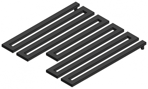
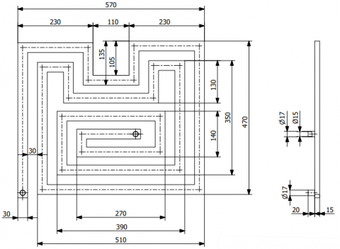
In the developed cooling system, the pipe used as a path for water flow has a rectangular spiral shape and a rectangular tube, as shown in Figure 1. The cooling pipe is made of stainless steel with a total length of 4.61 m, a cross-sectional area of 0.03 x 0.015 m, and a thickness of 0.001 m, with physical properties as shown in Table 3.
Table 3. Physical properties of stainless steel [29-31]
|
Parameters |
Specifications |
|
Specific heat |
507 J/kg.K |
|
Thermal conductivity |
16.27-20 W/m.K |
|
Density |
7800-7940 kg/m3 |
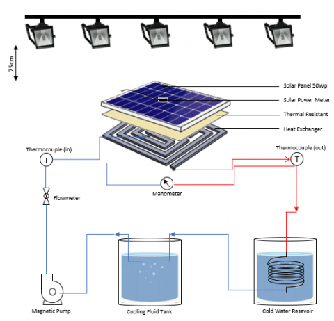
An experimental setup has been developed to study the effect of water cooling on the performance of a solar photovoltaic (PV) power plant. Sunwatt 50Wp solar PV installed at Universitas Sebelas Maret in Central Java, Indonesia. A heat exchanger with a rectangular tube and rectangular spiral configuration is installed at the bottom of the solar panel [32]. A solar simulator replaces the intensity of solar irradiation to get actual working conditions. This was done because of the limitations of outdoor testing, such as unpredictable weather conditions. Halogen lamps were chosen for use with this solar simulator because they are reliable, inexpensive, and readily available. The solar simulator is designed for a panel capacity of 50 Wp with an effective area of 16% and a non-uniformity of 2.61% [33]. Measurement and storage of panel temperature data using a K-type thermocouple with a data logger (Labjack-U6, US). Sensors are located at the top and bottom of the panel, inlet, and outlet. Measure the pressure difference using a Dwyer 490 digital manometer mounted on the inlet and outlet channels. The flowmeter is installed on the inlet pipe. Solar irradiation was measured with a Lutron SPM-1116SD solar meter [34]. The experimental setup carried out in this study can be shown in Figure 2.
(a)
(b)
Figure 1. Cooling pipe (a) rectangular tube and (b) rectangular spiral and (in mm)
Figure 2. Experiment setup
2.2 Performance analysis parameters
The energy balance equation determines the thermal energy exchange or heat transfer rate ($\dot{Q}$) on the waterside, which can be expressed as Eq. (1).
$\dot{Q}=\dot{m} \cdot C_p .\left(T_e-T_i\right)$ (1)
where, $\dot{m}$ is the mass flow rate, $T_i$ and $T_e$ are the average fluid temperatures at the inlet and outlet of the pipe. In an active cooling system, there is forced convection heat transfer which can be defined as Eq. (2) below,
$\dot{Q}=h \cdot A_s \cdot(\Delta T l m t d)$ (2)
Moreover, h is the heat transfer coefficient, As is the pipe surface area, $\Delta T \operatorname{lm} t d$ is the logarithmic mean temperature difference. To find the value of the heat transfer coefficient (h) can use Eq. (3) below [35].
h. $A_s \cdot(\Delta T \operatorname{lm} t d)=\dot{m} \cdot C_p \cdot\left(T_e-T_i\right)$ (3)
The temperature at the inlet and outlet lines must be calculated carefully. For the flow in the heat exchanger, the $\Delta T \operatorname{lm} t d$ can be calculated from Eq. (4)
$\Delta T \operatorname{lm} t d=\frac{T i-T e}{\ln [(T s-T e) /(T s-T i)]}=\frac{\Delta T e-\Delta T i}{\ln \left(\frac{\Delta T e}{\Delta T i}\right)}$ (4)
Energy efficiency $(\eta)$ is the ratio of the maximum power $\left(P_{M P P}\right)$ to the power from solar radiation received by solar cells $\left(I_{\text {light }}\right)$. At the same time, the power of solar radiation $\left(I_{\text {light }}\right)$ is obtained from the multiplication of the intensity of sunlight $\left(I_{r a d}\right)$to the active area of the solar cell (A). The value of the electrical efficiency of photovoltaic cells is inversely proportional to the significant increase in the operating temperature of the cell during the absorption of solar radiation [10]. In this case, the energy efficiency is written by Eqns. (5) and (6) as follows [36].
$\eta_{\text {elctrical }}=\frac{P_{M P P}}{I_{\text {light }}}=\frac{I_{S C} \times V_{O C} \times F F}{I_{\text {rad }} \times A}$ (5)
$\eta_{\text {thermal }}=\frac{m \times C_p \times \Delta T}{I_{\text {rad }} \times A}$ (6)
3.1 The analysis of the temperature change
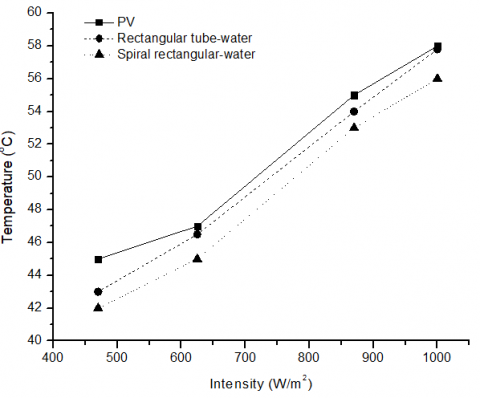
Solar PV working temperature is affected by many factors, including light intensity. Figure 3 shows a graph of working temperature against increasing light intensity. Temperature sensors are installed at the top and bottom of the solar panel to take the average. The graph shows that the working temperature when the intensity is 470 W/m2 is lower than when the intensity is 1000 W/m2. This is because an increase in light intensity will increase the working temperature of the Sunwatt 50Wp solar PV [37].
Figure 3. The graph of temperature changes
Sunwatt 50Wp solar PV without cooling shows a high working temperature compared to Sunwatt 50Wp solar PV with rectangular tubes and rectangular spiral water cooling. At an intensity of 1000 W/m2, the solar panel's temperature without cooling is 58℃. After being given cooling using a rectangular tube and rectangular spiral configuration, the temperature decreased to 57.4℃ and 56.6℃. In this case, it can be seen that cooling with a rectangular spiral shows a lower working temperature [38]. Using the cooling channel, as the water temperature increases, the temperature difference between the cooling channel and the water becomes smaller, so the heat transfer drops sharply.
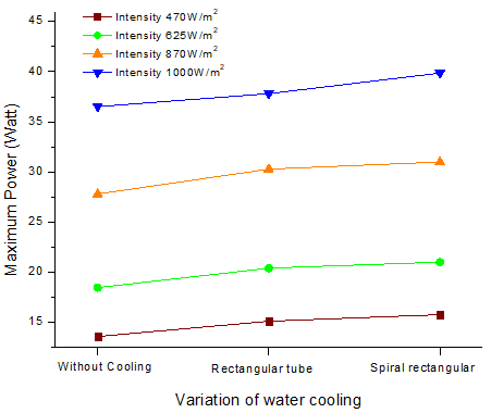
3.2 Comparison of power of spiral rectangular and rectangular tube configurations
The test results on the generated power show that Sunwatt 50Wp solar PV without cooling has a lower performance value than rectangular tube and rectangular spiral cooling. This value occurs at all light intensities tested. Figure 4 shows a graph of the different types of cooling on performance with variations in light intensity. The overall intensity shows that the spiral shows the highest value for all intensity variations.
When the solar panel temperature increases, the output power will decrease. The output power will increase if the light intensity increase [39]. Light intensity affects the output power of a solar cell in two ways: first, the stronger the light, the more photons hit the cell, and second, the photons must have sufficient energy to dislodge electrons from atoms in the cell. The number of photons hitting the cell increases with the light's intensity, but the light's wavelength determines the energy of the photons. Photons with too little energy will not knock electrons away, and photons with too much energy will not be absorbed by the solar cell. There comes the point where increasing light intensity does not increase power output. This is known as the saturation point. Once a solar cell reaches its saturation point, increasing the light intensity will not increase the power output.
Figure 4. Power changes in solar panels
3.3 Sunwatt 50Wp solar PV performance analysis
Figures 5 and 6 show the open circuit voltage (Voc) relationship to short-circuit current (Isc) and maximum power at 1000 W/m2 irradiation. From the two charts, we can see that the three lines have almost the same pattern. When the irradiation increases, the open circuit voltage also increases. The voltage generated by solar panels without cooling and water cooling with rectangular tubes and rectangular spirals are 21.5V, 22V, and 21.9V, respectively. Under the same conditions, the current generated by solar panels is 2.16A, 2.19A, and 2.2A. Sunwatt 50Wp solar PV without cooling generates lower voltages and currents than water-cooled panels. This is related to the project objective whereby when the irradiation is high, the ambient temperature also increases, and the panels overheat to the point where they are insufficient to convert energy. More than that, the current and voltage output of the solar panels will affect the maximum power generated.
Figure 5. Graph of current-voltage
Figure 6. Graph of power-voltage
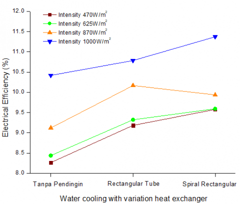
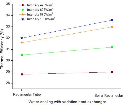
3.4 Efficiency
The test results in Figures 7 and 8 show an increase in electrical efficiency in Sunwatt 50Wp solar PV panels that use cooling. These results increased at all tested light intensities.
Figure 7. Electrical efficiency
Figure 8. Thermal efficiency
Solar panel efficiency is related to the panel temperature. At an intensity of 1000W/m2, the Sunwatt 50Wp solar PV without cooling achieves an electricity efficiency of 10.4%. The electrical efficiency of solar panels with rectangular tubes and rectangular water-cooling configurations is 10.7% and 11.3%. Thermal efficiency at the same test conditions reached 32% and 33.6%. Sunwatt 50Wp solar PV with water-cooled spiral configurations produce the highest electrical and thermal efficiency because they have lower temperatures than the other two test conditions. The addition of cooling channels under the solar panels will absorb heat from them [3]. Electrical efficiency will increase when the panel temperature is lower in conditions of higher intensity. At the same time, the thermal efficiency will increase when the temperature at the outlet increases because it absorbs more heat from the solar panels.
Various cooling methods for solar PV have been developed to increase efficiency, including forced convection using fluid media such as water. In this case, the heat exchanger configuration becomes one of the determining aspects of the resulting cooling performance. In this study, heat exchangers with rectangular and spiral rectangular tube configurations were identified in the convection cooling method using water fluid in solar PV panels. Based on the results that have been obtained, several things are obtained as follows:
Based on these results, the convection cooling method on solar PV panels using water fluid with a spiral rectangular tube configuration shows better results than the rectangular tube configuration. This is because the spiral rectangular tube configuration can absorb heat better, so it can lower the solar PV temperature more and maximize the resulting energy and thermal efficiency values.
The author acknowledges Universitas Sebelas Maret in their support (UNS). The Ministry of Research, Technology, and Higher Education of the Republic of Indonesia provided the total funding for this study through a grant from PDUPT 2022 with the title "Optimization of Cooling Systems to Improve Performance of Photovoltaic Solar Cells" (Research Grant Number 673.1/ UN27.22/PT.01.03/2022).
|
$\dot{Q}$ |
Heat transfer rate (J/s) |
|
$\dot{m}$ |
Mass flow rate (kg/s) |
|
$C_p$ |
Specific heat (J/kg.K) |
|
h |
Heat transfer coefficient (W/m2.K) |
|
Te |
Outlet pipe temperature (℃) |
|
Ti |
Inlet pipe temperature (℃) |
|
TS |
The surface temperature of solar PV panel (℃) |
|
$\Delta T$ |
The difference in fluid temperature at the outlet and inlet pipe (℃) |
|
$\Delta T l m t d$ |
The logarithmic mean temperature difference |
|
A |
The active area of the solar cell (m2) |
|
As |
Pipe surface area (m2) |
|
Ilight |
Power of solar radiation (W/m2) |
|
Irad |
The intensity of sunlight (W/m2) |
|
ISC |
Short-circuit current (Ampere) |
|
Voc |
Open circuit voltage (Volt) |
|
FF |
Fill Factor |
|
PMMP |
Maximum power (Watt) |
|
$\eta_{\text {elctrical }}$ |
Electrical efficiency (%) |
|
$\eta_{\text {thermal }}$ |
Thermal efficiency (%) |
|
$\eta$ |
Energy efficiency (%) |
[1] Ritchie, H., Roser, M., Rosado, P. (2022). Energy Our World in Data. https://ourworldindata.org/energy.
[2] Khan, J., Arsalan, M.H. (2016). Solar power technologies for sustainable electricity generation – A review. Renewable and Sustainable Energy Reviews, 55: 414-425. https://doi.org/10.1016/j.rser.2015.10.135
[3] Bashir, M.A., Ali, H., Amber, K., Ali, H., Imran, S., Kamran, M.S. (2016). Performance investigation of photovoltaic modules by back surface water cooling. Thermal Science, 22: 290-290. https://doi.org/10.2298/TSCI160215290B
[4] Pandian, A., Bansal, K., Thiruvadigal, D., Sakthivel, S. (2015). Fire hazards and overheating caused by shading faults on photo voltaic solar panel. Fire Technology, 52(2). https://doi.org/10.1007/s10694-015-0509-7
[5] Siecker, J., Kusakana, K., Numbi, B.P. (2017). A review of solar photovoltaic systems cooling technologies. Renewable and Sustainable Energy Reviews, 79: 192-203. https://doi.org/10.1016/j.rser.2017.05.053
[6] Grubišić-Čabo, F., Nizetic, S., Tina, G. (2016). Photovoltaic panels: A review of the cooling techniques. Transactions of FAMENA, 40: 63-74.
[7] Basam, K., Krishna, K., Pallipogu, V., Nukala, R. (2016). Experimental analysis of solar panel efficiency with different modes of cooling. International Journal of Engineering and Technology, 8(3): 1451-1456.
[8] Dwivedi, P., Sudhakar, K., Soni, A., Solomin, E., Kirpichnikova, I. (2020). Advanced cooling techniques of P.V. modules: A state of art Case Studies in Thermal Engineering, 21: 100674. https://doi.org/10.1016/j.csite.2020.100674
[9] Arifin, Z., Tribhuwana, B.A., Kristiawan, B., et al. (2022). The effect of soybean wax as a phase change material on the cooling performance of photovoltaic solar panel. Journal homepage: http://iieta. org/journals/ijht, 40(1): 326-332. https://doi.org/10.18280/ijht.400139
[10] Teo, H.G., Lee, P.S., Hawlader, M.N.A. (2012). An active cooling system for photovoltaic modules. Applied Energy, 90(1): 309-315. https://doi.org/10.1016/j.apenergy.2011.01.017
[11] Wu, S., Xiong, C. (2014). Passive cooling technology for photovoltaic panels for domestic houses. International Journal of Low-Carbon Technologies, 9(1): 118-126. https://doi.org/10.1093/ijlct/ctu013
[12] Al-Amri, F., Mallick, T.K. (2013). Alleviating operating temperature of concentration solar cell by air active cooling and surface radiation. Applied Thermal Engineering, 59(1): 348-354. https://doi.org/10.1016/j.applthermaleng.2013.05.045
[13] Abo-Elfadl, S., Yousef, M.S., Hassan, H. (2021). Assessment of double-pass pin finned solar air heater at different air mass ratios via energy, exergy, economic, and environmental (4E) approaches. Environmental Science and Pollution Research, 28(11): 13776-13789. https://doi.org/10.1007/s11356-020-11628-9
[14] Satpute, B.J., Rajan, A.J. (2018). Recent advancement in cooling technologies of solar photovoltaic (PV) system. FME Transactions, 46: 575-584. https://doi.org/0.5937/fmet1804575S
[15] Irwan, Y.M., Leow, W.Z., Irwanto, M., Fareq, M., Hassan, S.I.S., Safwati, I., Amelia, A.R. (2015). Comparison of solar panel cooling system by using dc brushless fan and dc water. In Journal of Physics: Conference Series, 622(1): 012001. https://doi.org/10.1088/1742-6596/622/1/012001
[16] Colt, G. (2016). 2016 International Conference on Applied and Theoretical Electricity (ICATE), Craiova, Romania, 2016, pp. 1-5. https://doi.org/10.1109/ICATE.2016.7754634
[17] Kabeel, A.E., Abdelgaied, M., Sathyamurthy, R. (2019). A comprehensive investigation of the optimization cooling technique for improving the performance of PV module with reflectors under Egyptian conditions. Solar Energy, 186: 257-263. https://doi.org/10.1016/j.solener.2019.05.019
[18] Smith, M.K., Selbak, H., Wamser, C.C., Day, N.U., Krieske, M., Sailor, D.J., Rosenstiel, T.N. (2014). Water cooling method to improve the performance of field-mounted, insulated, and concentrating photovoltaic modules. Journal of Solar Energy Engineering, 136(3): 034503. https://doi.org/10.1115/1.4026466
[19] Tang, X., Quan, Z., Zhao, Y. (2010). Experimental investigation of solar panel cooling by a novel micro heat pipe array. Energy Power Eng, 2(3): 171-174. https://doi.org/10.1109/APPEEC.2010.5449518
[20] Ibrahim, A., Sopian, K., Othman, M.Y., AlGhoul, M.A., Zaharim, A. (2008). Simulation of different configuration of hybrid photovoltaic thermal solar collector (PVTS) designs. Selected Papers from Communications & Information Technology, 1-3.
[21] Deshmukh, S., Palaskar, V. (2015). Performance analysis of a specially designed flow heat exchanger used in hybrid photovoltaic/thermal solar system. International Journal of Renewable Energy Research, 5: 476-482.
[22] Reda, M.N., Spinnler, M., Al-Kayiem, H.H., Sattelmayer, T.H.O.M.A.S. (2020). Analysis of ground thermal control systems for solar photovoltaic performance enhancement. WIT Transactions on Ecology and the Environment, 246: 41-50. https://doi.org/10.2495/EPM200051
[23] Al-Waeli, A.H., Sopian, K., Kazem, H.A., Yousif, J.H., Chaichan, M.T., Ibrahim, A., Mat, S., Ruslan, M.H. (2018). Comparison of prediction methods of PV/T nanofluid and nano-PCM system using a measured dataset and artificial neural network. Solar Energy, 162: 378-396. https://doi.org/10.1016/j.solener.2018.01.026
[24] He, W., Chow, T.T., Ji, J., Lu, J., Pei, G., Chan, L.S. (2006). Hybrid photovoltaic and thermal solar-collector designed for natural circulation of water. Applied Energy, 83(3): 199-210. https://doi.org/10.1016/j.apenergy.2005.02.007
[25] Karami, N., Rahimi, M. (2014). Heat transfer enhancement in a PV cell using Boehmite nanofluid. Energy Conversion and Management, 86: 275-285. https://doi.org/10.1016/j.enconman.2014.05.037
[26] Al-Shamani, A.N., Sopian, K., Mat, S., Hasan, H.A., Abed, A.M., Ruslan, M.H. (2016). Experimental studies of rectangular tube absorber photovoltaic thermal collector with various types of nanofluids under the tropical climate conditions. Energy Conversion and Management, 528-542. https://doi.org/101016/jenconman201607052
[27] Krauter, S. (2004). Increased electrical yield via water flow over the front of photovoltaic panels Solar Energy Materials and Solar Cells, 82(1): 131-137. https://doi.org/10.1016/j.solmat.2004.01.011
[28] Arifin, Z., Prasetyo, S., Tribhuwana, B., Tjahjana, D., Rachmanto, R., Kristiawan, B. (2022). Photovoltaic performance improvement with phase change material cooling treatment. International Journal of Heat and Technology, 40(4): 953-960. https://doi.org/10.18280/ijht.400412
[29] Sârbu, I., Dorca, A. (2018). Review on heat transfer analysis in thermal energy storage using latent heat storage systems and phase change materials. International Journal of Energy Research, 43: 29-64. https://doi.org/10.1002/er.4196
[30] Ricotta, M., Meneghetti, G., Atzori, B., Risitano, G., Risitano, A. (2019). Comparison of experimental thermal methods for the fatigue limit evaluation of a stainless steel. Metals, 9(6): 677. https://doi.org/10.3390/met9060677
[31] Liu, Z., Yu, Z.J., Yang, T., et al. (2019). Numerical modeling and parametric study of a vertical earth-to-air heat exchanger system. Energy, 172: 220-231. https://doi.org/10.1016/j.energy.2019.01.098
[32] Prasetyo, S., Prabowo, A., Arifin, Z. (2022). Investigation of thermal collector nanofluids to increase the efficiency of photovoltaic solar cells. International Journal of Heat and Technology, 40(2): 415-422. https://doi.org/10.18280/ijht.400208
[33] Arifin, Z., Kuncoro, I.W., Hijriawan, M. (2021). Solar simulator development for 50 WP solar photovoltaic experimental design using halogen lamp. International Journal of Heat and Technology, 39(6): 1741-1747. https://doi.org/10.18280/ijht.390606
[34] Arifin, Z., Prasetyo, S.D., Tjahjana, D.D.D.P., Rachmanto, R.A., Prabowo, A.R., Alfaiz, N.F. (2022). The application of TiO2 nanofluids in photovoltaic thermal collector systems. Energy Reports, 8: 1371-1380. https://doi.org/10.1016/j.egyr.2022.08.070
[35] Nguyen, C., Galanis, N., Polidori, G., Fohanno, S., Popa, C., Bechec, A. (2009). An experimental study of a confined and submerged impinging jet heat transfer using Al2O3-Water nanofluid. International Journal of Thermal Sciences, 48: 401-411. https://doi.org/10.1016/j.ijthermalsci.2008.10.007
[36] Gangadevi, R., Vinayagam, B., Raja, S. (2017). Experimental investigations of hybrid PV/Spiral flow thermal collector system performance using Al2O3 /water nanofluid. IOP Conference Series: Materials Science and Engineering, 197: 012041. https://doi.org/10.1088/1757-899X/197/1/012041
[37] Li, N.J., Quan, Z.H., Zhao, Y.H., Guo, N.N. (2012). The experimental study of new-type water-cooling PV/T collector. Advanced Materials Research, 242-247. https://doi.org/10.4028/www.scientific.net/AMR.374-377.242
[38] Prasetyo, S.D., Prabowo, A.R., Arifin, Z. (2022). The effect of collector design in increasing PVT performance: Current state and milestone. Materials Today: Proceedings, 63: S1-S9. https://doi.org/10.1016/j.matpr.2021.12.356
[39] Huang, B.W., Tseng, J.G., Hsiao, D.R. (2014). Sun intensity and angle on efficiency of solar cell system. In Applied Mechanics and Materials, 627: 182-186. https://doi.org/10.4028/www.scientific.net/AMM.627.182