Ka’er Zhu | Ruochong Zhou* | Ping Gao | Jie Wang | Fei Luo
© 2022 IIETA. This article is published by IIETA and is licensed under the CC BY 4.0 license (http://creativecommons.org/licenses/by/4.0/).
OPEN ACCESS
It is of practical significance to analyze the time-sharing and zoning heat load demand and fine heating control of large heating buildings in order to reduce the building energy consumption. The existing research lacks the time-sharing and zoning form of refined heating for different functional zones of large heating buildings. For this reason, this paper carried out the time-sharing and zoning heat load demand analysis and research on heating control of large heating buildings. First, the mathematical model for the main heating links of the heating system of the large building based on the heat balance equation is constructed to realize the simulation of the dynamic change of the performance of the large building heating system. Then, the size, characteristics and influencing factors of heat load of various heating units in the building are analyzed, and three possible ways of mass regulation, mass-flow regulation and intermittent regulation that can change the flow by stages are introduced. The experimental results verify the effectiveness of the proposed heating control mode, which can effectively reduce the building heating energy consumption.
large buildings, time sharing and zoning, heat load demand, heating control
In recent years, with the promotion of urbanization in China, large buildings or annexed buildings have shown a trend of increasing year after year [1-5]. However, due to the lack of practical heating energy saving strategies, most new buildings still use the traditional continuous undifferentiated centralized heating mode. Although most of the heat load demand has been met, it has led to the waste of heating energy consumption in some building areas with low heat load demand, which hinders the implementation of energy conservation and emission reduction policies advocated in China [6-12]. In particular, the heating energy consumption of large buildings is higher in cities with a heating cycle of 5-6 months and in severe cold climate regions [13, 14]. Therefore, it is of practical significance and an urgent need to conduct time sharing and zoning heat load demand analysis and refined heating control research for large heating buildings to reduce the energy consumption.
Building energy consumption prediction has become an important research issue in the context of sustainable housing and smart city. Wang et al. [15] proposed a set model, which has higher performance in cooling and heating load prediction. In addition, the effects of different performance on heating and cooling loads are also studied. Chaganti et al. [16] proposed IEHO–BP neural network algorithm and applied the new algorithm to building cooling and heating load forecasting. The experimental results show that compared with other swarm intelligent optimization algorithms, the output results of the cooling and heating load forecasting model based on IEHO–BP neural network algorithm are more accurate and have less oscillation. Wang et al. [17] proposed that the zoning system can adjust the working state of equipment according to user preferences to meet the heat demand of each area, monitor the air temperature, and ensure the thermal comfort in each area. Under the framework of this goal, compared with complex and expensive control systems, Hernández et al. [18] proposed a new zone control system, which is based on the thermostat and electric damper, control board and communication gateway in each zone, allowing communication between the unit and control board to set operating parameters such as fan speed or air supply set point temperature. The results show that the thermal zoning control is helpful to adapt the thermal energy to each zone in a more effective way.
At this stage, domestic and foreign scholars have conducted in-depth research on time-sharing and zoning heating, and preliminarily explored the heating mode that comprehensively considers the heating time, space and temperature differences, but the division of the above factors is not clear, and there is a lack of research on refined time-sharing and zoning heating mode for different functional zones of large heating buildings. For this reason, this paper carried out an analysis of the time-sharing and zoning heat load demand and heating control research of large heating buildings. First, in Chapter 2, the mathematical model of the main heating links of the large building heating system based on the heat balance equation is constructed to simulate the dynamic changes of the heating system performance of the large building. Then, in Chapter 3, the size, characteristics and influencing factors of heat load of various heating units in the building are analyzed, and three possible methods of mass regulation, mass flow regulation and intermittent regulation that may be used to change the flow by stages are introduced. The experimental results verify the effectiveness of the proposed heating control mode, which can effectively reduce the building heating energy consumption.
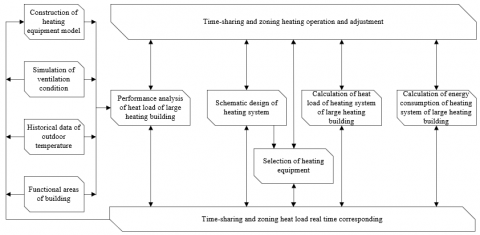
In order to accurately describe the operation of the large building heating system, the comprehensive effect of various heating parameters on the heating performance of the large building heating system is explored. Figure 1 shows the schematic diagram of the heating control framework of the large building heating system. In this paper, the mathematical model of the main heating links of the large building heating system is built based on the heat balance equation to realize the simulation of the dynamic changes of the performance of the large building heating system.
Figure 2 shows the relationship diagram of zoning heating equipment of large heating buildings. It can be seen from the figure that the specific heating links include heat exchanger, heating pipe network, variable frequency water pump and radiator. The specific modeling process is as follows:
In order to obtain larger average temperature difference, large building heating systems often use countercurrent heat exchangers to improve the heat exchange effect of cold and hot water in the pipe network and the economic benefits of heating. Assuming that the efficiency of the heat exchanger and the inlet temperature of cold and hot fluids are respectively expressed by p1r and p2f, and the minimum heat capacities of hot and cold fluids are expressed by Dmin, then the ratio of the actual heat exchange capacity of the heat exchanger Ẇ to the maximum heat exchange capacity Ẇmax is the efficiency ρ of the heat exchanger, which can be calculated by the following formula:
$\rho=\frac{\dot{W}}{\dot{W}_{\max }}=\frac{N_2 d_2\left(p_{2 r}-p_{2 f}\right)}{D_{\min }\left(p_{1 r}-p_{2 f}\right)}=\frac{N_1 d_1\left(p_{1 r}-p_{1 f}\right)}{D_{\min }\left(p_{1 r}-p_{2 f}\right)}$ (1)
$\dot{W}=\rho \dot{W}_{\max }=\rho D_{\min }\left(p_{1 r}-p_{2 f}\right)$ (2)
The outlet temperature p2r and p1f of the cold and hot fluid side of the heat exchanger can be calculated by the following formula:
$p_{2 r}=\frac{\rho \dot{W}_{\max }}{N_2 d_2}+p_{2 f}=\frac{\rho D_{\min }\left(p_{1 r}-p_{2 f}\right)}{N_2 d_2}+p_{2 f}$ (3)
$p_{1 f}=p_{1 r}-\frac{\rho \dot{W}_{\max }}{N_1 d_1}=p_{1 r}-\frac{\rho D_{\min }\left(p_{1 r}-p_{2 f}\right)}{N_1 d_1}$ (4)
The heat transfer coefficient HT of heat exchanger can be calculated by the following equation:
$H T=\left\{\begin{array}{l}\frac{\dot W}{\frac{\left(p_{1 r}-p_{2 f}\right)-\left(p_{1 f}-p_{2 f}\right)}{\ln \frac{p_{1 r}-p_{2 f}}{p_{1 f}-p_{2 f}}}}\quad,\left(p_{1 r}-p_{2 f}\right) \neq\left(p_{1 f}-p_{2 f}\right) \\ \frac{\dot{W}}{\frac{\left(p_{1 r}-p_{2 f}\right)+\left(p_{1 f}-p_{2 f}\right)}{2}}\quad,\left(p_{1 r}-p_{2 f}\right) \neq\left(p_{1 f}-p_{2 f}\right)\end{array}\right.$ (5)
The heating pipe network of large building heating system is large and long, which leads to the difference in heat loss and heat storage in the actual heating process of large buildings. In this paper, the long pipe of heating pipe network is divided into several pipe segments with uniform fluid temperature. It is assumed that the mass flow of the fluid in the pipe is expressed by ṅ, the temperature of the fluid in the jth pipe section is expressed by Pj, the temperature of the external environment of the pipe is expressed by Pout, the time step is expressed by Δp, the comprehensive heat loss coefficient of the pipeline is represented by HT, the thermal resistance of the inner wall of the pipeline and the pipeline fluid is represented by SIN, the thermal resistance of the pipeline is represented by RPI, the thermal resistance of the insulation layer is represented by STN, the thermal resistance of the outer wall of the insulation layer of the pipeline and the external environment is represented by SOU, and the heat dissipation of the jth pipe section to the external environment is represented by ẆEN,j. The product of Δp and ṅ determines the length of the pipe section unit, so the temperature of the fluid flowing out of the pipe can be calculated by the following formula:
$P_o=\frac{1}{\dot{n} \Delta p} \sum_{j=1}^{l-1}\left(N_j P_j+\beta N_l P_l\right)$ (6)
$\sum_{j=1}^{l-1}\left(N_j+\beta N_l\right)=\dot{n} \Delta p(0 \leq \beta \leq 1)$ (7)
$H T=\frac{1}{S_{I N}+S_{P I}+S_{T N}+S_{O U}}$ (8)
$N_j D_T \frac{d P_j}{d p}=-(H T)\left(P_j-P_{E N}\right)$ (9)
$\dot{W}_{E N, j}=(H T)_j\left(P_j-P_{o u t}\right)$ (10)
Large building heating system has the demand of energy conservation, so its heating pipe network usually uses frequency conversion water pump with small power consumption. Assuming that the head of delivery of the pump under rated working condition is expressed by F0, the corresponding flow is expressed by R, and the coefficient of the head of delivery-flow relationship is expressed by β0, β1 and β2, then there is the following unary quadratic polynomial expression:
$F_0=\beta_0+\beta_1 R+\beta_2 R^2$ (11)
The working frequency of the water pump can be adjusted according to the actual working conditions. Assuming that the four parameters of pump speed, flow, head of delivery and power under a certain working condition are respectively represented by m, R, F and T, the parameters under corresponding rated working conditions are represented by m0, R0, F0 and T0, and the speed ratio of the pump is represented by k, the following equations shall be met for similar working conditions when adjusting the pump frequency:
$\frac{m}{m_0}=\frac{R}{R_0}=\left(\frac{F}{F_0}\right)^{1 / 2}=\left(\frac{T}{T_0}\right)^{1 / 3}=k$ (12)
Figure 1. Schematic diagram of heating control framework for heating system of large building
Figure 2. Diagram of the relationship of zoning heating equipment of large heating building
By combining the above two expressions, the following expression of head of delivery-flow curve cluster can be obtained:
$F=k^2 \beta_0+k \beta_1 R+\beta_2 R^2$ (13)
When the pump works with a certain frequency, its corresponding working state point is determined. Assuming that the operating state points of the water pump at the speed of m1, m2 and m3 are represented by x, y and z, the lifting pressure of the water pump ΔT can be calculated by the following formula:
$\Delta T=\frac{\phi r F}{1000}$ (14)
Assuming that the full efficiency is represented by EFOV and the mechanical efficiency is represented by EFMO, the pump efficiency EFPU can be calculated by the following formula:
$E F_{P U}=\frac{E F_{O V}}{E F_{M O}}$ (15)
Assuming that the pump flow is expressed by ṅ, the shaft power ṪSHA can be calculated by the following formula:
$\dot{T}_{S H A}=\frac{\dot{n} \Delta T}{\phi E F_{P U}}$ (16)
The calculation formula of input power Ṫ is:
$\dot{T}=\frac{\dot{T}_{O V}}{E F_{M O}}$ (17)
Assuming that the proportion of motor heat lost to the fluid is expressed by gMO, the heat transmitted to the fluid by the water pump when the fluid goes through the water pump can be calculated by the following formula:
$\dot{W}_{F L}=\dot{T}_{S H A}\left(1-E F_{P U}\right)+\left(\dot{T}-\dot{T}_{S H A}\right) g_{M O}$ (18)
The calculation formula of the heat release ẆAM from the pump to the environment is as follows:
$\dot{W}_{A M}=\left(\dot{T}-\dot{T}_{S H A t}\right)\left(1-g_{M O}\right)$ (19)
The calculation formula of fluid temperature PF, OU at pump outlet is:
$P_{F L, O U}=P_{F L, i n}+\frac{\dot{W}_{F L}}{\dot{n} D_t}$ (20)
The radiators of different heating units of the large building heating system are considered as a whole. The temperature of supplied water and returned water entering a heating unit through the pipe network are represented by pr and pf respectively. The coefficient related to the heat transfer coefficient of the radiator is represented by x and y, and the radiator area is represented by G. The heat dissipation capacity of the radiator can be calculated by the following formula:
$W=x G\left(\frac{p_r+p_f}{2}-p_m\right)^{1+y}$ (21)
$W=R d\left(p_r-p_f\right)$ (22)
The function types of different heating units in large heating buildings are complex and diverse, so the key to heat control and operation management of large heating buildings is to explore the size, characteristics and influencing factors of heat load of various heating units in buildings.
In heating season, the heat load of large heating buildings is periodic. The heat load of different heating units in large heating buildings varies with time change of the daily activities of people in the buildings. The main activity areas of people in the daytime are mainly concentrated in the production area, living area, office and learning area. During this period, the heat demand in buildings is high. At noon, most people are active in restaurants and rest areas. At this time, there is a large demand for heat in these areas. At night, people are scattered for home activities. At this time, the heat demand of all heating units in large buildings is small.
In the traditional operation and regulation mode of heating system, the response speed of quality regulation is slow, and the power consumption of water pump is large, while the quantity regulation is easy to cause hydraulic imbalance. Figure 3 shows the schematic diagram of time-sharing and zoning heating control system for large heating buildings. According to the heating demand characteristics of large heating buildings, the time-sharing and zoning heating operation regulation mode is selected in this paper. The following three possible modes, namely, quality regulation, quality-flow regulation and intermittent regulation that change the flow by stages are introduced.
The quality regulation mode of phased variable flow is to divide the heating season into several sub stages according to the outdoor temperature of the heating building. Different sub stages adopt different quality regulation modes. The method has the advantages of simple execution process, low power consumption and high hydraulic stability. The flow ratio of each sub stage can be calculated by the following formula:
The quality regulation mode of phased variable flow is to divide the heating season into several sub-stages according to the outdoor temperature of the heating building. Different sub-stages adopt different quality regulation modes. The method has the advantages of simple execution process, low power consumption and high hydraulic stability. The flow ratio of each sub-stage can be calculated by the following formula:
$\mu=\bar{R}=C O$ (23)
The corresponding calculation formula of supplied and returned water temperature is given by the following formula:
$p_r=p_m+0.5\left(p_r^{\prime}+p_f^{\prime}-2 p_m^{\prime}\right) \bar{W}^{1 /(1+y)}+0.5 \frac{\left(p_r^{\prime}-p_f^{\prime}\right)}{\mu} \bar{W}$ (24)
$p_f=p_m+0.5\left(p_r^{\prime}+p_f^{\prime}-2 p_m^{\prime}\right) \bar{W}^{1 /(1+y)}-0.5 \frac{\left(p_r^{\prime}-p_f^{\prime}\right)}{\mu} \bar{W}$ (25)
Mass-flow regulation is to synchronously regulate the hot water circulation flow and supply water temperature of the heating system pipe network of large heating buildings. This regulation mode features inferior hydraulic stability and less water pump power consumption, but automatic heating control system needs to be equipped, so the basic cost of heating is high. When the mass-flow adjustment mode is adopted, let Δp*=pr-pf/p’r-p’f, then:
$\bar{W}=\bar{R} \Delta p^*$ (26)
After the logarithm transformation of the above formula, the following formula is obtained:
$\frac{\lg \bar{R}}{\lg \bar{W}}+\frac{\lg \Delta p^*}{\lg \bar{W}}=1$ (27)
The flow optimization adjustment coefficient n and quality optimization adjustment coefficient m of the heating system are defined to represent the impact of flow adjustment and quality adjustment on the operation adjustment of the heating system of large heating buildings, which are expressed by the following formula:
$n=\frac{\lg \bar{R}}{\lg \bar{W}}, \quad m=\frac{\lg \Delta p^*}{\lg \bar{W}}$ (28)
The value range of n and m is 0~1, and after the deformation of the above formula, the following is obtained:
$\bar{R}=\bar{W}^n$ (29)
$\Delta p^*=\bar{W}^m$ (30)
When n=1 and m=0, the heating system of large heating buildings adopts quantity regulation, and the designed temperature difference of the heating system is the temperature difference between supply water and return water. When m=1 and n=0, the heating system of large heating buildings adopts quality regulation, and the designed flow of the heating system is the cyclic flow. The following formula gives the calculation formula of supply water and return water temperature under this regulation mode:
$p_r=p_m+0.5\left(p_r^{\prime}+p_f^{\prime}-2 p_m^{\prime}\right) \bar{W}^{1 /(1+y)}+0.5\left(p_r^{\prime}-p_f^{\prime}\right) \bar{W}^{1-n}$ (31)
$p_f=p_m+0.5\left(p_r^{\prime}+p_f^{\prime}-2 p_m^{\prime}\right) \bar{W}^{1 /(1+y)}-0.5\left(p_r^{\prime}-p_f^{\prime}\right) \bar{W}^{1-n}$ (32)
Intermittent regulation mode does not regulate the hot water circulation flow and water supply temperature of the pipe network of the heating system of large heating buildings. It only adjusts the daily heating duration, and the water pump consumes less power. However, there is a problem that the heat demand of remote heating units cannot be met in real time. When intermittent regulation is adopted, the circulation flow and water supply temperature of the heating system in large heating buildings are fixed. With the increase of outdoor temperature, the daily working time k of the heating system decreases. Assuming that the outdoor temperature at the beginning of intermittent regulation is expressed by p''q, the calculation formula of k is given by the following formula:
$k=24 \frac{p_m-p_q}{p_m-p_q^{\prime \prime}}$ (33)
Figure 3. Schematic diagram of time-sharing and zoning heating control system for large heating buildings
The heating units of large heating buildings are divided based on the functional types of different areas, and the division results are given in Table 1.
Table 2 shows the heat load analysis results of each heating unit. It can be seen from the table that the operation regulation modes of the heating system involved in the analysis include quality regulation (mode 1), quality-flow regulation (mode 2) and intermittent regulation (mode 3), which change the flow by stages. Generally, the heat load coefficient of the top floor heating unit is much higher than that of the bottom floor when Mode 1 and Mode 2 are adopted, and the heat load coefficient of the middle floor may be higher when Mode 3 is adopted. Comparing the heat load of each heating unit under the three modes, it can be seen that the difference between the three heating modes is that Mode 3 lowers the designed heating temperature of the secondary heating units with relatively dispersed working hours, and the corresponding average heat load coefficient is less than 1, while the heat load coefficient of the main heating units with long working hours is increased, making the average heat load coefficient greater than 1.
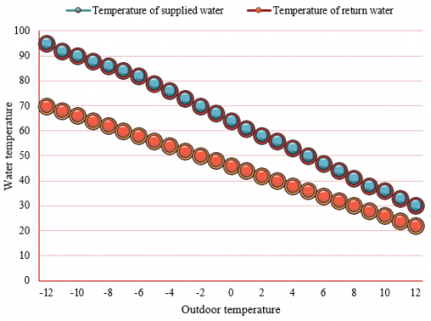
Figure 4. Water temperature regulation curve under intermittent regulation mode
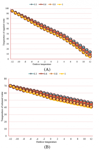
In this paper, the experimental analysis is carried out by taking the time-sharing and zoning heating system of an teaching area in a university as an example. The designed temperature of the supply and return water of the heating pipe network is 95/70℃ respectively. The water temperature regulation curve under the intermittent regulation mode is shown in Figure 4. The water temperature regulation curve under different flow optimization regulation coefficients is shown in Figure 5(A), (B).
Figure 5. Water temperature regulation curve under different flow optimization regulation coefficients
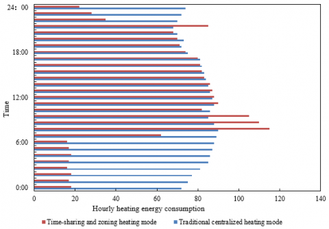
Figure 6. Comparison of energy consumption between traditional centralized heating mode and time-sharing and zoning heating mode
Table 1. Results of heating unit division of large heating building
|
Number of main heating unit |
Covered area |
Working hours |
Number of secondary heating unit |
Covered area |
Working hours |
|
001 |
415 |
00:00-24:00 |
101 |
125 |
8:00-9:00 |
|
002 |
436 |
00:00-24:00 |
102 |
362 |
8:00-9:00 |
|
003 |
328 |
7:00-23:00 |
103 |
125 |
7:00-9:00 |
|
004 |
262 |
7:00-23:00 |
104 |
263 |
15:00-18:00 |
|
005 |
302 |
7:00-23:00 |
105 |
392 |
14:00-18:00 |
|
006 |
152 |
7:00-23:00 |
106 |
574 |
16:00-18:00 |
|
007 |
135 |
7:00-23:00 |
107 |
602 |
16:00-19:00 |
Table 2. Heat load analysis of each heating unit
|
Number of heating unit |
Average heat load coefficient |
||
|
Way 1 |
Way 2 |
Way 3 |
|
|
001 |
1.20/1.36/1.69 |
1.48/1.62/1.38 |
1.04/1.36/1.07 |
|
002 |
1.01/1.69/1.34 |
1.14/1.62/1.59 |
1.30/1.29/1.25 |
|
003 |
1.04/1.03/1.27 |
1.03/1.59/1.27 |
1.14/1.06/1.28 |
|
004 |
1.92/1.37/1.42 |
-- |
0.13/0.55/0.79 |
|
005 |
1.36/1.27/1.82 |
1.07/1.62/1.95 |
1.51/1.39/1.27 |
|
006 |
1.30/1.59/1.37 |
-- |
0.25/0.68/0.71 |
|
007 |
1.52/1.37/1.48 |
-- |
0.02/0.67/0.85 |
|
101 |
1.39/1.35/1.14 |
1.04/1.69/1.57 |
1.27/1.27/1.30 |
|
102 |
1.67/1.28/1.11 |
1.20/1.62/1.84 |
1.05/1.27/1.39 |
|
103 |
1.69/1.57/1.05 |
1.38/1.29/1.07 |
1.28/1.14/1.09 |
|
104 |
1.69/1.84/1.37 |
-- |
0.32/0.61/0.88 |
|
105 |
1.50/1.36/1.51 |
1.62/1.30/1.69 |
1.20/1.25/1.37 |
|
106 |
1.81/1.26/1.95 |
-- |
0.25/0.68/0.83 |
|
107 |
1.37/1.52/1.48 |
-- |
0.46/0.51/0.82 |
It can be seen from the Figure 6 that compared with the traditional centralized heating mode, the heating energy consumption under the time-sharing and zoning heating mode adopted in this paper is significantly lower, which can reduce nearly 1/4 of the heating energy consumption. It is found from the analysis that the time-sharing and zoning heating method adopted in this paper greatly reduces the heating energy consumption at 0:00~6:00 at night, and reduces the heating design temperature of the secondary heating units with relatively scattered working hours. It is only necessary to maintain the temperature of the corresponding heating units within the low temperature range that can meet the needs of comfortable temperature. Based on the above analysis, the time-sharing and zoning heating adopted in this paper has obvious advantages in energy consumption.
In this paper, the analysis of time-sharing and zoning heat load demand and research on heating control of large heating buildings are studied. First, the mathematical model of the main heating links of the heating system of the large building based on the heat balance equation is constructed to realize the simulation of the dynamic change of the performance of the heating system of the large scale building. Then, the size, characteristics and influencing factors of heat load of various heating units in the building are analyzed, and three possible ways of mass regulation, mass flow regulation and intermittent regulation that can change the flow by stages are introduced. Combined with the experiment, the heating units are divided based on the functional types of different areas of large heating buildings, and the heat load analysis results of each heating unit are provided. The water temperature regulation curve under the intermittent regulation mode and the water temperature regulation curve under the conditions of different flow optimization regulation coefficients are drawn, and the energy consumption of the traditional centralized heating mode and time-sharing and zoning heating mode are compared, which verifies that time-sharing and zoning heating adopted in this paper has obvious advantages in energy consumption.
[1] Ye, Y., Strong, M., Lou, Y., Faulkner, C. A., Zuo, W., Upadhyaya, S. (2022). Evaluating performance of different generative adversarial networks for large-scale building power demand prediction. Energy and Buildings, 269: 112247. https://doi.org/10.1016/j.enbuild.2022.112247
[2] Liu, S., Zou, Y., Ji, W., Zhang, Q., Ahmed, A., Han, X., Zhang, S. (2022). Energy-saving potential prediction models for large-scale building: A state-of-the-art review. Renewable and Sustainable Energy Reviews, 156: 111992. https://doi.org/10.1016/j.rser.2021.111992
[3] Wang, L., Zhong, J., Zhang, P. (2022). Collaborative design of large-scale building's energy saving structure based on green BIM concept. International Journal of Global Energy Issues, 44(2-3): 217-232. https://doi.org/10.1504/IJGEI.2022.121401
[4] Sun, Y., Mou, L., Wang, Y., Montazeri, S., Zhu, X.X. (2022). Large-scale building height retrieval from single SAR imagery based on bounding box regression networks. ISPRS Journal of Photogrammetry and Remote Sensing, 184: 79-95. https://doi.org/10.1016/j.isprsjprs.2021.11.024
[5] Guo, J., Li, K., Xu, H. (2022). A local enhancement method for large-scale building facade depth images using densely matched point clouds. Advances in Multimedia, 2022: 3175998. https://doi.org/10.1155/2022/3175998
[6] Jiang, D., Cui, H., Jiang, K., Yang, J. (2019). Study building heat storage operation strategy for air-to-water heat pumps connected to a residential floor heating system. In IOP Conference Series: Earth and Environmental Science, IOP Publishing, 227(4): 042054. https://doi.org/10.1088/1755-1315/227/4/042054
[7] Bu, X., Ran, Y., Zhang, D. (2019). Experimental and simulation studies of geothermal single well for building heating. Renewable Energy, 143: 1902-1909. https://doi.org/10.1016/j.renene.2019.06.005
[8] Du, T., Sun, Y. (2019). Correlation of building heating and air qualities in typical cities of China. Energy Procedia, 158 6532-6537. https://doi.org/10.1016/j.egypro.2019.01.105
[9] Shen, P., Dai, M., Xu, P., Dong, W. (2019). Building heating and cooling load under different neighbourhood forms: Assessing the effect of external convective heat transfer. Energy, 173: 75-91. https://doi.org/10.1016/j.energy.2019.02.062
[10] Wen, Z.M., Zhang, F.H. (2019). Feasibility analysis of residential building adopts household fireplace instead of centralized heating in Dezhou. In IOP Conference Series: Earth and Environmental Science, IOP Publishing, 295(3): 032023. https://doi.org/10.1088/1755-1315/295/3/032023
[11] Chen, C., Shao, H., Naumov, D., Kong, Y., Tu, K., Kolditz, O. (2019). Numerical investigation on the performance, sustainability, and efficiency of the deep borehole heat exchanger system for building heating. Geothermal Energy, 7(1): 1-26. https://doi.org/10.1186/s40517-019-0133-8
[12] Zhao, B.C., Wang, R.Z. (2019). Perspectives for short-term thermal energy storage using salt hydrates for building heating. Energy, 189: 116139. https://doi.org/10.1016/j.energy.2019.116139
[13] Wei, S., Wang, X.X., Jones, R., de Wilde, P. (2018). Using building performance simulation to save residential space heating energy: A pilot testing. Proceedings-Windsor Conference 2014: Counting the Cost of Comfort in a Changing World, pp. 1115-1124.
[14] Zhu, L., Yang, Y. (2019). Numerical study on the thermal performance of pipe-embedded PCM building envelope in the heating season. Energy Procedia, 158: 2663-2670. https://doi.org/10.1016/j.egypro.2019.02.019
[15] Wang, C., Zhu, Y., Guo, X. (2019). Thermally responsive coating on building heating and cooling energy efficiency and indoor comfort improvement. Applied Energy, 253: 113506. https://doi.org/10.1016/j.apenergy.2019.113506
[16] Chaganti, R., Rustam, F., Daghriri, T., Díez, I.D.L.T., Mazón, J.L.V., Rodríguez, C.L., Ashraf, I. (2022). Building heating and cooling load prediction using ensemble machine learning model. Sensors, 22(19): 7692. https://doi.org/10.3390/s22197692
[17] Wang, H.J., Jin, T., Wang, H., Su, D. (2022). Application of IEHO-BP neural network in forecasting building cooling and heating load. Energy Reports, 8: 455-465. https://doi.org/10.1016/j.egyr.2022.01.216
[18] Hernández, F.F., Suárez, J.M.P., Cantalejo, J.A.B., Muriano, M.C.G. (2022). Impact of zoning heating and air conditioning control systems in users comfort and energy efficiency in residential buildings. Energy Conversion and Management, 267: 115954. https://doi.org/10.1016/j.enconman.2022.115954