Li Feng
© 2022 IIETA. This article is published by IIETA and is licensed under the CC BY 4.0 license (http://creativecommons.org/licenses/by/4.0/).
OPEN ACCESS
The machining error caused by the thermal deformation of machines or tools accounts for half or even more in the total error, and the machining precision could be improved by stabilizing the heat balance of the process system. However, few of the existing studies have concerned about the thermal deformation law caused by the high-speed self-feed spindle system that could meet the performance requirements of high-speed cutting in precision machining, therefore, it’s of great necessity to study the thermal properties of precision machinery. For this reason, this paper took the precision machinery with a high-speed self-feed spindle system as the subject to study its thermal properties and thermal error compensation. At first, this paper introduced the composition of the precision machining control system and analyzed the thermal properties of the subject. Then, the heat source and heat exchange forms of the precision machinery were analyzed, the thermal intensity of the internal and external heat sources during the machining process was calculated, and the corresponding thermal boundary conditions were given. After that, this paper divided the heat sources of the subject during high-speed cutting into two types: internal heat source and external environment heat source, and carried out analysis. Moreover, this paper gave the structure of a thermal error and temperature synchronous measurement system for precision machinery, integrated the features of the thermal error data of two groups of high-speed cutting process, and built a thermal error compensation model based on the Bayesian network. At last, experimental results verified the effectiveness of the model.
precision machining, thermal property analysis, heat source analysis, thermal error compensation model
To meet the application requirements of advanced technologies such as large-scale integrated circuits, and lasers, the precision machining technology has been developed rapidly in recent years and it has improved the machining precision of conventional machining method by more than one order of magnitude [1-4]. Precision machining has high requirements for raw materials, equipment, tools, environment, quality supervision, and other aspects. Now we have already known that the unsatisfactory precision of work pieces and the machining error during precision machining are mainly caused by the process system and the internal stress, and thermal error and geometric error are the most common error types [5-10]. The machining error caused by the thermal deformation of machines or tools accounts for half or even more in the total error, so the thermal error has become the primary error source of precision machining.
In order to avoid and solve the thermal error of precision machining, measures could be taken from the aspect of stabilizing the heat balance of the process system to improve the machining precision [11-20]. Therefore, figuring out the generation mechanism of the thermal error of precision machinery and building thermal error model for it are conductive to formulating effective thermal error compensation schemes and reducing thermal error, thereby ensuring the machining precision of the products.
Reddy et al. [11] discussed to use feed-forward backpropagation neural network to develop real-time thermal error compensation model for precision machine tools and simplified it with the regression analysis technique, the paper also talked about the development of algorithm for real-time compensation module, and its implementation on open architecture CNC controller; the developed module was then successfully tested on a diamond turning machine and proved to be effective. Lei et al. [21] used extra information, namely the low-cost unlabeled temperature data that are easily accessible under various operation conditions, to enrich the thermal error modeling data for feed axes; they employed co-training semi-supervised support vector machines for regression to build a thermal error-temperature model for feed axes which contains the pattern information of the unlabeled data when modeling; then thermal experiments were performed on two cases of different axes to attain the labeled data of temperature and thermal error and the unlabeled data of only temperature under different operating speeds. To provide solutions for the high cost and scarcity of thermal error data collection of precision feeding system, Zhu et al. [22] proposed a modeling and thermal error compensation strategy for precision feeding system based on co-training support vector machine regression. This strategy built a thermal error model by integrating labeled data such as temperature error and thermal error and unlabeled temperature data, and then compensating the compensation method based on Siemens 840D NC system. To improve the accuracy of fiber-optic inertial navigation system when it’s applied in a thermal changing environment, Zhuo and Du [23] studied an integrated high precision identification and compensation method for the thermal effect error of inertial instruments, and implemented system-level calibration within the full temperature range to establish high accurate calibration parameter references. Liu et al. [24] proposed a data-driven thermal error compensation method for high speed and precision five-axis machine tools based on homogeneous transformation, then the compensation component was attained from the analysis of the error transmission chain of machine tools and was expressed as the transmission matrix consisting of thermal error terms of linear axes and spindle system according to the differential movement of the compensation axis.
Although existing studies have modelled the thermal error of precision machine tools such as the three-axis CNC machine tools and the CNC grinding machinery, and most of these models could accurately predict the thermal error of precision machinery, however, most of the research objects of thermal error are typical, and few of the existing studies have concerned about the thermal deformation law caused by the high-speed self-feed spindle system that could meet the performance requirements of high-speed cutting in precision machining, therefore, it’s of great necessity to study the thermal properties of precision machinery, so this paper aims to take precision machinery with a high-speed self-feed spindle system as the subject to study its thermal properties and thermal error compensation. In the second chapter, this paper introduced the composition of the precision machining control system, discussed the thermal properties of the subject based on the heat transfer theory, analyzed the heat source and heat exchange forms of precision machinery, calculated the thermal intensity of the internal and external heat sources during the machining process, and gave the corresponding thermal boundary conditions. In the third chapter, this paper divided the heat sources of the subject during high-speed cutting into two types: Internal heat source and external environment heat source, and carried out analysis. In the fourth chapter, this paper gave the structure of a thermal error and temperature synchronous measurement system for precision machinery, integrated the features of the thermal error data of two groups of high-speed cutting process, and built a thermal error compensation model based on the Bayesian network. At last, experimental results verified the effectiveness of the model.
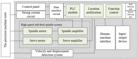
Figure 1 shows the composition of the control system of precision machine tools. As can be seen from the figure, the system consists of the driving device, velocity and displacement detection system, data interface module, PLC module, control panel, human-machine interface, location control interface, and function control interface, etc.
Analyzing the thermal properties of the subject based on the structure of precision machinery and the characteristics of high-speed self-feed cutting can help us master the laws of its thermal error and then build model for it. At first, this paper analyzed the thermal properties of the subject based on heat transfer theories, then, it analyzed the heat source and heat exchange forms of precision machinery, calculated the thermal intensity of the internal and external heat sources during the machining process, and gave the corresponding thermal boundary conditions.
During the high-speed self-feed cutting, the changes of the machine’s own temperature are mainly caused by the heat source as it emits heat and transfers the heat outward. For precision machine tools with a high-speed self-feed spindle system, there’re three heat transfer methods: heat conduction, heat convection, and heat radiation, and their corresponding heat transfer formulas are given by Formulas 1-3. Assuming: ηDR represents the heat flux of heat conduction; dP/dm represents the temperature gradient; SDR represents the heat conduction area; μ represents the thermal conductivity of the material, then there is:
$\eta_{D R}=-\mu S_{D R} \frac{d P}{d m}$ (1)
Assuming: ηdr represents the heat flux of heat convection; fdr represents the convective heat transfer; Pgb and Plt respectively represent the solid surface temperature and the fluid temperature, then there is:
$\eta_{d r}=f_{d r}\left(P_{g b}-T_{l t}\right)$ (2)
Figure 1. Composition of the control system of precision machine tools
Assuming: ρ represents the heat emissivity of the machine itself; η1 represents the heat flux of heat radiation; BM represents the surface area; ε represents the Stefan-Boltzmann constant; p represents the thermodynamic temperature of black body, then there is:
$\eta_1=\rho B M \varepsilon p^4$ (3)
The analysis of thermal properties is to analyze the machining temperature field and the thermal deformation of the machine caused by the temperature change, therefore, attaining accurate machining temperature field is the necessary condition. Assuming: ξ represents the density of the material; SH represents the specific heat capacity of the material; Ωu represents unit volume heat of the heat source; then the differential equation of heat conduction shown in Formula 4 can solve the temperature field of the precision machinery with high-speed self-feed spindle system:
$\frac{\partial P}{\partial p}=\frac{\mu}{\xi S H}\left(\frac{\partial^2 P}{\partial a^2}+\frac{\partial^2 P}{\partial b^2}+\frac{\partial^2 P}{\partial c^2}\right)+\frac{\Omega_u}{\xi S H}$ (4)
For the subject, the corresponding solutions could be attained based on different initial conditions of the cutting processing and other boundary conditions such as instantaneous temperature, heat flux density, heat convection, and heat conduction, and the initial condition is the temperature distribution of the precision machinery at the beginning of the cutting, then there is:
$(T)_{t=0}=f(x, y, z)$ (5)
The formula below gives the boundary condition that characterizes the heat transfer law between the machine body and the surrounding medium. Assuming: PBM represents the surface temperature of the machine, if the instantaneous temperature at any point on the machine body is known, then there is:
$P_{B M}=g(p)$ (6)
Assuming: μ represents the coefficient of thermal conductivity, if the normal heat flux density on the surface of the machine body is known, then there is:
$-\mu\left(\frac{\partial P_{B M}}{\partial m}\right)_{B M}=g(p)$ (7)
Assuming: PGT and PLT respectively represent the solid surface temperature and the fluid temperature; γ represents the coefficient of convective heat transfer, if the situation of the convective heat exchange between the machine body and the surrounding fluid is known, then there is:
$-\mu\left(\frac{\partial P}{\partial m}\right)_{G T}=\gamma\left(P_{G T}-P_{L T}\right)$ (8)
Assuming: Pr and Po respectively represent the contact surface temperature of two machine parts, the heat transfer between the two is heat conduction, by default it’s considered that the contact surface temperatures of two are the same, then there is:
$P_r=P_o$ (9)
The machining error during high-speed cutting is mainly caused by the thermal deformation of each part of the machine, moreover, due to the uneven temperature distribution and the different constraints, there’re differences in the thermal deformation of each part of the machine during the machining process. Assuming: β represents the linear expansion coefficient; ρa, ρb, ρc represent the positive strain components in the three directions of a, b, and c; αab, αac, αbc represent the shear strain components in the directions of a-b, a-c, and b-c. Then, based on the elastic mechanics and thermo-elastic mechanics, the elastic deformation produced when the temperature of the machine body changes is:
$\rho_a=\rho_b=\rho_c=\beta P$$\alpha_{b c}=\alpha_{a c}=\alpha_{a b}=0$ (10)
Because the machine body subjected to external constraints and internal self-constraints cannot deform freely, thermal stress would generate inside the machine body and cause it to deform. Assuming: ρa, ρb, ρc represent the positive strain components in the three directions of a, b, and c; αab, αac, αbc represent the shear strain components in the directions of a-b, a-c, and b-c; εa, εb, εc represent the positive thermal stress components in the three directions of a, b, and c; φab, φac, φbc represent the thermal shear stress components in the directions of a-b, a-c, and b-c; λ represents the Poisson’s ratio; TX represents the elastic modulus; JQ represents the shear modulus; β represents the linear expansion coefficient, then the total deformation of the machine body composed of two kinds of deformations caused by elastic deformation and thermal stress can be calculated by the following formula:
$\left\{\begin{array}{l}\rho_a=\frac{1}{T X}\left[\varepsilon_a-\lambda\left(\varepsilon_b+\varepsilon_c\right)\right]+\beta P \\ \rho_b=\frac{1}{T X}\left[\varepsilon_b-\lambda\left(\varepsilon_a+\varepsilon_c\right)\right]+\beta P \\ \rho_c=\frac{1}{T X}\left[\varepsilon_c-\lambda\left(\varepsilon_a+\varepsilon_c\right)\right]+\beta P \\ \alpha_{b c}=\frac{1}{J Q} \varphi_{b c}, \alpha_{a c}=\frac{1}{J Q} \varphi_{a c}, \alpha_{a b}=\frac{1}{J Q} \varphi_{a b}\end{array}\right.$ (11)
The heat source during high-speed cutting of the subject can be divided into two types: internal heat source, and external environment heat source. Within a short time, the temperature change of the external environment heat source is relatively small, and the temperature changes of the internal heat sources, including the friction heat, the bearing heat, and the motor heat, are relatively large, so between these two types of heat sources, the internal heat source is the main cause of the thermal error of the machine.
During the high-speed self-feed cutting process of the spindle system, assuming: W represents the thermal power of cutting; FQX represents the main cutting force; υ represents the rotating speed of the spindle, then the amount of heat generated by cutting can be calculated by the following formula:
$W=F_{Q X} v$ (12)
Assuming: LJ represents the average cutting torque during the high-speed self-feed cutting process of precision machinery; n represents the normal modulus of the gear; JG represents the amount of axial feeding; CD represents the feeding depth of the cutter; υ0 represents the rotating speed of the spindle; CS represents the number of gear teeth; ϕCL represents the correction coefficient of gear material; ϕYD represents the correction coefficient of the hardness of the gear material; ϕLX represents the correction coefficient of the helical angle; GJ represents the outer diameter of the hob cutter; then the average cutting torque can be calculated by the following formula:
$LJ=4.02 n^{1.75} J G^{0.65} P^{0.81} u_0^{-0.26} C S^{0.27} \varphi_{C L} \varphi_{Y D} \varphi_{L X}$ (13)
$F_{Q X}=L J /(G J / 2)$ (14)
A lot of heat will be generated when the sliding bearing and the rolling bearing of the subject get close to the high-speed spindle, under the action of this heat, thermal deformation that can cause machining error would occur to the high-speed spindle. Assuming: U represents the sliding speed of the bearing; G1 represents load on the sliding bearing; g represents the sliding friction factor; CJ represents the diameter of the bearing; m represents the rotating speed of the spindle; then, the calculation formula of the thermal power w1 of the sliding bearing is:
$w_1=g G_1 U$ (15)
$U=\frac{\pi C J m}{1000 \times 60}$ (16)
Assuming: LJ represents the total friction torque; m represents the rotating speed of the spindle; then the thermal power w2 of the rolling bearing can be calculated by the following formula:
$w_2=1.047 \times 10^{-4} L J \cdot m$ (17)
Assuming: 0LJ0 and LJ1 represent the viscous friction torque of the bearing and the friction torque of the load on it, then the total torque can be expressed as:
$L J=L J_0+L J_1$ (18)
Assuming: g0 represents the constant related to the type of the bearing and its lubrication method; g1 represents the constant related to the type of the bearing and the load on it; u represents the kinematic viscosity of the lubricating oil; f represents the rotating speed of the spindle; t1 represents the calculated load of the friction torque of the bearing; ZJn represents the middle diameter of the bearing; T0 represents the equivalent static load of the rolling bearing; De represents basic fixed static load of the rolling bearing; Gs and Gx represent the radial and axial forces, then there are:
$L J_0=\left\{\begin{array}{l}10^{-7} \cdot g_0 \cdot(v n)^{2 / 3} \cdot Z J_n^3, v n \geq 2000 \\ 160 \cdot 10^{-7} \cdot g_0 \cdot Z J_n^3, v n<2000\end{array}\right.$ (19)
$L J_1=g_1 \cdot t_1 \cdot Z J_n$ (20)
The heat loss generated during the operation of the motor of the high-speed self-feed spindle system will be transmitted out in the forms of heat conduction, heat convection, and heat radiation. Assuming: WDF represents the amount of heat generated by the motor; TDF represents the input power; δDF represents the efficiency of the motor; NJ1 represents the output torque of the motor; mDF represents the rotating speed of the motor, then the formula for calculating the amount of heat generated by the motor is:
$W_{D F}=W_{D F}\left(1-\delta_{D F}\right)-\left(\frac{1-\delta_{D F}}{\delta_{D F}}\right)$ (21)
Figure 2 shows the structure of the synchronous measurement system for precision machining thermal error and temperature. The thermal error measurement and temperature measurement were respectively realized by the eddy current sensor and the temperature sensor, and the host computer was used to display and store the collected temperature data and thermal error data. Figure 3 gives the thermal error compensation flow for the precision machinery.
Bayesian network model is widely used in artificial intelligence, machine learning and other fields, and is suitable for dealing with the relationship between uncertain variables in uncertain problems.
In order to compensate the thermal error of precision machinery, in this paper, the features of the thermal error data of two sets of high-speed machining process were synthesized. At first, the thermal error model was constructed based on the thermal error data of the machine spindle collected from four key thermal points. Assuming: VF(ΔO|ΔP1, ΔP2, ΔP3, ΔP4) represents the posterior probabilities under the condition that the temperature variables of the four key points are known, then, based on the estimation and calculation of VF(ΔO|ΔP1, ΔP2, ΔP3, ΔP4), the Bayesian network thermal error model was built. Assuming: ΔP represents the difference between adjacent sample points of the temperature variable; ΔO represents the difference between adjacent sample points of the thermal error data of the machine, then, according to the Bayesian theorem, we have:
$V F(X \mid Y)=\frac{V F(Y \mid X) V F(X)}{V F(Y)}$ (22)
Based on the above formula, there is:
$V F\left(\Delta O \mid \Delta P_1, \Delta P_2, \Delta P_3, \Delta P_4\right)$$=\frac{V F\left(\Delta P_1, \Delta P_2, \Delta P_3, \Delta P_4 \mid \Delta O\right) V F(\Delta O)}{V F\left(\Delta P_1, \Delta P_2, \Delta P_3, \Delta P_4\right)}$ (23)
In the formula, VF(ΔP1, ΔP2, ΔP3, ΔP4|ΔO), and the temperature variable of the four key thermal points was assumed to be independent of each other, so there is:
$V F\left(\Delta P_1, \Delta P_2, \Delta P_3, \Delta P_4 \mid \Delta O\right)$$=V F\left(\Delta P_1 \mid \Delta O\right) V F\left(\Delta P_2 \mid \Delta O\right)$$V F\left(\Delta P_3 \mid \Delta O\right) V F\left(\Delta P_4 \mid \Delta O\right)$ (24)
Apply full probability formula to VF(ΔP1,ΔP2,ΔP3,ΔP4|ΔO), then there is:
$V F(Y)=\sum_{i=1}^m V F\left(X_i\right) V F\left(Y \mid X_i\right)$ (25)
$V F\left(\Delta P_1, \Delta P_2, \Delta P_3, \Delta P_4\right)$$=\sum_{i=1}^m V F\left(O_i\right) V F\left(\Delta P_1, \Delta P_2, \Delta P_3, \Delta P_4 \mid \Delta O_i\right)$ (26)
Figure 2. Structure of the synchronous measurement system for precision machining error and temperature
Figure 3. The thermal error compensation flow for precision machinery
Assuming: m represents the category number of thermal error O, based on above analysis, the posterior probability could be attained as:
$V F\left(\Delta O \mid \Delta P_1, \Delta P_2, \Delta P_3, \Delta P_4\right)$$=V F\left(\Delta P_1 \mid \Delta O\right) V F\left(\Delta P_2 \mid \Delta O\right)$$=\frac{V F\left(\Delta P_3 \mid \Delta O\right) V F\left(\Delta P_4 \mid \Delta O\right) V F(\Delta O)}{\sum_{i=1}^m V F\left(O_i\right) V F\left(\Delta P_1, \Delta P_2, \Delta P_3, \Delta P_4 \mid \Delta O_i\right)}$ (27)
The posterior probability of the Bayesian network was the value of VF(ΔO|ΔP1,ΔP2,ΔP3,ΔP4|), for all thermal error categories, the denominators in the formula were the same, so the calculation process was simplified:
$b=V F\left(\Delta P_1 \mid \Delta O\right) V F\left(\Delta P_2 \mid \Delta O\right)$$V F\left(\Delta P_3 \mid \Delta O\right) V F\left(\Delta P_4 \mid \Delta O\right) V F(\Delta O)$ (28)
After the thermal error model was built, assuming: $l$ represents the data group number; $j, n, m, t$, and $c$ represent the state domain number, then by calculating $\left\{V F_l\left(\triangle O_j \mid \triangle P_{1 n}, \triangle P_{2 t}, \triangle P_{3 m}, \triangle P_{4 c}\right)\right\}$, the state domains of variable $\triangle O_j$ with a maximum probability of 1-10 could be attained, and it's determined that the prediction interval of the thermal error value $\triangle O_l$ was the state domain of the thermal error corresponding to $j$ at this time, and the thermal error compensation value was the median value of the state domain. Assuming: $O_{l+1}$ represents the thermal error value of the $l+1-$ th group; $O_l$ represents the thermal error value of the $l$-th group; $\Delta O_l$ represents the difference between the thermal error values of the $l+1$-th group and the $l$-th group, then there is:
$O_{l+1}=O_l+\Delta O_l$ (29)
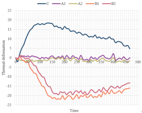
Experiments were carried out according to the flow of the synchronous measurement of thermal error and temperature, then data of the spindle temperature and thermal deformation of the machine at four key points were collected and plotted into Figure 4, showing the changes of the thermal deformation of the precision machinery with time. According to the figure, after the experiment had started for 450 minutes, the heat source positions and the heat deformations of the precision machinery had basically reached a thermal equilibrium state, the maximum thermal error in the directions of A, B, and C was respectively 3.2 mum, 23.4 mum and 18.9 mum, and the maximum thermal error was 15.4 mum. That is, for the subject, the thermal error in A direction was the smallest and compensation was not needed; the thermal errors in directions B and C were larger, and compensation was required. According to the spindle temperature and thermal deformation data measured at the key points of the machine, a thermal error prediction model was constructed for the subject, and the specific thermal error compensation operations were realized by inputting the compensated interpolation values into the control system to perform reverse spindle compensation control.
The intercept and slope of the thermal error curve are important parameters that describe the influence of the temperature of the machine itself on its thermal error. Table 1 shows the results of the correlation analysis between the precision machinery’s temperature and its thermal error, and gives the correlation coefficients. As can be seen from the data, the intercept and slope were highly correlated. After fully considered the actual installation conditions of the sensor, the key thermal points closer to both the spindle motor heat source and the joint part of bearing and guide rail pair could be selected as representative heat sources.
Based on the correlation analysis results given above, four key thermal points had been selected as representatives to reflect the specific temperature change states of the internal heat source of the high-speed self-feed spindle system and the thermal error-sensitive components. In order to effectively reduce the influence of the temperature of external environment heat source of the system on the thermal error prediction model, the model was built based on the temperature rise of the four key thermal points relative to the external environment heat source of the system, and the key thermal point temperature rise and thermal error parameters are listed in Table 2.
Figure 4. The curve of thermal deformation of precision machinery
Figure 5. Comparison of the high-speed self-feed spindle system before and after thermal error compensation
Table 1. Correlation analysis results of temperature and thermal error of precision machinery
|
Temperature variable |
Correlation coefficient |
Sorting of correlation |
|
|
Slope |
Intercept |
||
|
P1 |
0.958 |
0.814 |
6 |
|
P2 |
0.915 |
0.849 |
5 |
|
P3 |
0.968 |
0.872 |
8 |
|
P4 |
0.947 |
0.859 |
4 |
|
P5 |
0.911 |
0.826 |
1 |
|
P6 |
0.928 |
0.811 |
3 |
|
P7 |
0.936 |
0.968 |
7 |
|
P8 |
0.951 |
0.915 |
2 |
Table 2. The temperature rise of key thermal points and the thermal error parameters
|
Temperature rise time |
Intercept |
Slope |
Temperature rise at key point |
|
|
32 |
0.84597 |
0.847 |
2.69 |
1.37 |
|
65 |
1.32655 |
1.26 |
4.35 |
1.29 |
|
95 |
2.51028 |
1.284 |
4.17 |
2.17 |
|
121 |
2.58 |
1.269 |
5.29 |
2.64 |
|
153 |
3.62514 |
1.352 |
5.34 |
2.38 |
|
184 |
3.61257 |
1.485 |
5.11 |
2.05 |
|
216 |
3.52915 |
2.51 |
5.69 |
2.49 |
Table 3. Comparison of prediction performance of different thermal error models
|
Prediction model |
Residual standard deviation |
Residual range |
||
|
Direction A |
Direction B |
Direction A |
Direction B |
|
|
Conventional BPNN |
7.15 |
2.49 |
[-13.26, 17.95] |
[-4.16, 5.28] |
|
GA-optimized network |
5.29 |
1.35 |
[-12.05, 12.3] |
[-0.82, 4.35] |
|
PSO-optimized network |
1.37 |
0.45 |
[-2.17, 3.67] |
[-1.27, 1.75] |
|
The proposed model |
1.29 |
0.31 |
[-5.49, 5.24] |
[-1.69, 1.28] |
In order to further verify the effectiveness of the constructed thermal error model, this paper designed a comparative experiment for the performance of different machine learning algorithms, and Table 3 gives the results of the comparative experiment. Indicators of prediction performance included the predicted residual standard deviation and the predicted residual range in directions A and B.
According to the table, in directions A and B, the predicted residual standard deviation of the proposed model was 1.29 μm and 0.31 μm respectively, the minimum value of the predicted residual standard deviation of the proposed model was the largest, and its prediction range was narrower, indicating that compared with the conventional BP neural network (BPNN), genetic algorithm-optimized (GA-optimized) network, and particle swarm optimization-optimized (PSO-optimized) network, its prediction accuracy was higher, and its stability was better.
The constructed thermal error compensation model was then embedded into the integrated compensation control hardware module, and the thermal error compensation flow of the precision machinery was experimented according to the test verification method, then the data of the thermal displacement of the precision machinery before and after thermal error compensation were collected. Figure 5 compares the high-speed self-feed spindle system before and after thermal error compensation. As can be seen from the figure, after thermal error compensation had been turned on, the change interval of the thermal displacement of precision machining showed significant convergence, which indicated that the constructed thermal error model had a good fitting effect. The fitted residual standard deviation of the B-axis and the C-axis had reduced to 1.04 μm and 1.24 μm.
This paper took precision machinery with a high-speed self-feed spindle system as subject to study its thermal properties and thermal error compensation. At first, this paper introduced the composition of the precision machining control system, discussed the thermal properties of the subject based on the heat transfer theory, analyzed the heat source and heat exchange forms of precision machinery, calculated the thermal intensity of the internal and external heat sources during the machining process, and gave the corresponding thermal boundary conditions. Then, this paper divided the heat sources of the subject during high-speed cutting into two types: internal heat source and external environment heat source, carried out analysis, gave the structure of a thermal error and temperature synchronous measurement system, integrated the features of the thermal error data of two groups of high-speed cutting process, and built a thermal error compensation model based on the Bayesian network.
Then in the experimental part, this paper plotted data curves of the thermal deformation of precision machinery, and the experimental results verified that the thermal error of the subject in the A direction was smaller, and thermal error compensation was not necessary; while the thermal errors of the subject in directions B and C were larger, so the thermal errors need to be compensated. After that, the correlation between the precision machinery’s temperature and its thermal error was analyzed, and the temperature rise of the key thermal points and the thermal error parameters were given. Experimental results verified that the proposed thermal error model outperformed the conventional BPNN, GA-optimized network, and PSO-optimized network in terms of accuracy and stability. At last, this paper compared the thermal error of the high-speed self-feed spindle system, and the results showed that after thermal error compensation had been turned on, the change interval of the thermal displacement of precision machining showed significant convergence, and it proved that the constructed thermal error model showed a good fitting effect.
[1] Guo, J., Wang, X.Y., Zhao, Y., Hou, C.Y., Zhu, X., Cai, Y.D., Kang, R.K. (2022). On-machine measurement of tool nose radius and wear during precision/ultra-precision machining. Advances in Manufacturing, 10(3): 1-14. https://doi.org/10.1007/s40436-022-00397-y
[2] Wojciechowski, S. (2021). Estimation of minimum uncut chip thickness during precision and micro-machining processes of various materials—a critical review. Materials, 15(1): 59. https://doi.org/10.3390/ma15010059
[3] Zhao, W., Qu, J., Li, J., Su, N., Shi, G., Liu, J. (2022). Research on quality analysis of solid-liquid two-phase abrasive flow precision machining based on different sub-grid scale models. The International Journal of Advanced Manufacturing Technology, 119(3): 1693-1706. https://doi.org/10.1007/s00170-021-07604-3
[4] Guo, J., Wang, C., Kang, C. (2022). Editorial for the special issue on “frontiers of ultra-precision machining”. Micromachines, 13(2): 220. https://doi.org/10.3390/mi13020220
[5] Shahinian, H., Zaytsev, D., Navare, J., Su, Y., Kang, D., Ravindra, D. (2019). Micro laser assisted machining (µ-LAM) of precision optics. In Optical Fabrication and Testing, OT1A-5. https://doi.org/10.1364/OFT.2019.OT1A.5
[6] Zhang, L., Yang, Z., Fang, Z., Cheng, J. (2022). Effects of laser parameters on machining precision and quality of wave-permeable materials. Journal of Laser Applications, 34(1): 012001. https://doi.org/10.2351/7.0000402
[7] Wang, S.M., Lee, C.Y., Gunawan, H., Yeh, C.C. (2022). On-line error-matching measurement and compensation method for a precision machining production line. International Journal of Precision Engineering and Manufacturing-Green Technology, 9(2): 493-505. https://doi.org/10.1007/s40684-021-00336-5
[8] Qiao, X., Zhang, Y., Meng, D. (2022). The progress and perspectives of nanotechnology applied in nontraditional precision machining processes for advanced industrial applications. Recent Patents on Nanotechnology, 16(1): 18-29. https://doi.org/10.2174/1872210515666210114092329
[9] Dai, J., Xu, W., OuYang, F. (2022). Precision analysis of noncircular gears based on CNC machining technology under cloud computing platform. Shock and Vibration. https://doi.org/10.1155/2022/1359084
[10] Ning, P., Zhao, J., Ji, S., Li, J., Dai, H. (2022). Tool path generation of ultra-precision machining an off-axial four-mirror anastigmat system based on accuracy active control. In Seventh Asia Pacific Conference on Optics Manufacture and 2021 International Forum of Young Scientists on Advanced Optical Manufacturing (APCOM and YSAOM 2021), 12166: 145-150. https://doi.org/10.1117/12.2605536
[11] Reddy, T.N., Shanmugaraj, V., Vinod, P., Krishna, S.G. (2020). Real-time thermal error compensation strategy for precision machine tools. Materials Today: Proceedings, 22: 2386-2396. https://doi.org/10.1016/j.matpr.2020.03.363
[12] Wei, X., Miao, E., Liu, H., Liu, S., Chen, S. (2019). Two-dimensional thermal error compensation modeling for worktable of CNC machine tools. The International Journal of Advanced Manufacturing Technology, 101(1): 501-509. https://doi.org/10.1007/s00170-018-2918-5
[13] Liu, K., Liu, H., Li, T., Liu, Y., Wang, Y. (2019). Intelligentization of machine tools: comprehensive thermal error compensation of machine-workpiece system. The International Journal of Advanced Manufacturing Technology, 102(9): 3865-3877. https://doi.org/10.1007/s00170-019-03495-7
[14] Gurauskis, D., Kilikevičius, A., Kasparaitis, A. (2021). Thermal and geometric error compensation approach for an optical linear encoder. Sensors, 21(2): 360. https://doi.org/10.3390/s21020360
[15] Yang, S., Luo, X., Chen, X., Luo, Z. (2021). Self-adaptive compensation method of thermal error for hobbing machine tool. International Journal of Innovative Computing, Information and Control, 17(6): 2045-2055. https://doi.org/10.24507/ijicic.17.06.2045
[16] Zimmermann, N., Breu, M., Mayr, J., Wegener, K. (2021). Autonomously triggered model updates for self-learning thermal error compensation. CIRP Annals, 70(1): 431-434. https://doi.org/10.1016/j.cirp.2021.04.029
[17] Hsu, C., Rao, G., He, C., Xu, J. (2021). Thermal error analysis and compensation in structured light system by virtual-point-based method. In 2021 IEEE 11th Annual International Conference on CYBER Technology in Automation, Control, and Intelligent Systems (CYBER), pp. 373-378. https://doi.org/10.1109/CYBER53097.2021.9588241
[18] Du, L., Lv, F., Li, R., Li, B. (2021). Thermal error compensation method for CNC machine tools based on deep convolution neural network. In Journal of Physics: Conference Series, 1948(1): 012165. https://doi.org/10.1088/1742-6596/1948/1/012165
[19] Wei, X., Ye, H., Feng, X. (2022). Year-Round Thermal Error Modeling and Compensation for the Spindle of Machine Tools Based on Ambient Temperature Intervals. Sensors, 22(14): 5085. https://doi.org/10.3390/s22145085
[20] Polyakov, A.N., Parfenov, I.V. (2019). Thermal error compensation in CNC machine tools using measurement technologies. In Journal of Physics: Conference Series, 1333(6): 062021. https://doi.org/10.1088/1742-6596/1333/6/062021
[21] Lei, M., Yang, J., Wang, S., Zhao, L., Xia, P., Jiang, G., Mei, X. (2019). Semi-supervised modeling and compensation for the thermal error of precision feed axes. The International Journal of Advanced Manufacturing Technology, 104(9): 4629-4640. https://doi.org/10.1007/s00170-019-04341-6
[22] Zhu, X., Zhao, L., Lei, M., Wang, S., Ling, Z., Yang, J., Mei, X. (2019). Co-Training support vector machine regression modeling and compensation for thermal error of precision feed system. Hsi-An Chiao Tung Ta Hsueh/Journal of Xi'an Jiaotong University, 53(10): 40-47.
[23] Zhuo, C., Du, J. (2018). Integrated high precision identification and compensation method for thermal effect error of fiber-optic inertial navigation system. Chinese Journal of Integrative Medicine, 4: 26-34.
[24] Liu, J., Ma, C., Wang, S. (2020). Data-driven thermally-induced error compensation method of high-speed and precision five-axis machine tools. Mechanical Systems and Signal Processing, 138: 106538. https://doi.org/10.1016/j.ymssp.2019.106538