Bashir E. Kareem* | Ahmed M. Adham | Banipal N. Yaqob
© 2022 IIETA. This article is published by IIETA and is licensed under the CC BY 4.0 license (http://creativecommons.org/licenses/by/4.0/).
OPEN ACCESS
The building projects' power consumption and CO2 emissions are 40% and 33%, respectively. It is a viable strategy to use phase change material in energy storage to provide free cooling. There are few studies on free cooling in hot climates, so the proposed system uses paraffin as a thermal storage material for free cooling and ventilation. The project contains a cooling tower, a horizontal slab heat exchanger between air and phase change material, and an indirect compact heat exchanger between air and water. The energy equation is computed using Engineering Equation Solver software to assess the overall system perform properly. The model investigated the parameters that affect the system's performance under various climate conditions. The system has improved indoor air quality by providing ventilation and extending the period of thermal comfort. The system's performance is determined by the cooling tower's performance and the Air to PCM and Air to water heat exchangers. The Air to PCM heat exchanger reduces supply temperature by 2°C with a slight pressure drop < 20Pa and does not affect system power consumption.
free ventilation, hot-dry climate, PCMs, thermal energy storage
Increasing energy consumption, concerns about climate change, and even reducing limited fossil fuel resources are all significant issues. Renewable energy is an alternative to fossil fuel energy. Using it in building projects is critical due to its high energy consumption [1]. Renewable energy is difficult to implement since it is inherently intermittent, inefficient, and unreliable [2]. Energy demand rises in lockstep with energy production, although there is a disparity between the two. When considerable stress is put on a power plant in a short period, it may decrease its lifespan and diminish system efficiency. Energy consumption must be shifted from peak to peak off power periods to rectify the mismatch between energy generation and consumption. In Iraq-Erbil, building energy usage was 62% in 2015 [3], compared to 40% globally [4]. Energy Storage is a great way to manage and bridge the gap between demand and supply energy. Buildings are an ideal location for Thermal Energy Storage (TES) implementation due to their high energy usage. TES can be used as an active or passive system. Chemical, sensible, and latent heat storages are the three types of TES. The thermal mass of the building structure might be used as a sensible storage system by the temperature change of the structure. Latent Heat Thermal Energy Storage (LHTES) outperforms other storages for its higher heat capability within a limited volume with minor expansion. It has a little temperature differential during a phase change (isothermal melting/solidification temperature). LHTES is more appealing than sensible storage [5]. The Free Cooling System (FCS) will store cool energy in the TES at night and reuse it throughout the day. FCS can only be used when the daily range temperature falls within the thermal comfort range, and it is most effective when the daily range temperature is the highest [6]. A significant quantity of energy could be kept in Phase Change Materials (PCMs) during phase shifts among solid, liquid, and gas phases in just a tight temperature change. Heat Transfer Fluids (HTF), such as air or water, have been widely used to melt and solidify PCM [7]. Recently, PCM applications have garnered attention due to their high density and commercial availability [8]. PCM is divided into three categories: inorganic, organic, and eutectic. Paraffin is an organic PCM widely used for its favorable thermophysical properties [9-11]. PCMs have a high storage density, making them ideal for storing thermal energy. The phase transition between solid and liquid is commonly used in TES because most PCMs are flammable at high temperatures [12]. Using PCM within TES is an excellent strategy for passive cooling and heating in buildings. Combining PCM and TES is an effective method for storing free cooling throughout the night for later usage during hot periods of the day [13]. PCM use is hampered by its high thermal resistance, which causes heat transfer to be delayed. Later, high thermal conductivity nanoparticles were added to microencapsulated PCM for heat transfer enhancement [14]. Heating and cooling systems could be eliminated or limited to specific hours of the day when PCM can be charged by cool night air and discharged by hot day air. Passive cooling/heating and energy-efficient technologies are concerned with improving indoor thermal comfort and lowering energy consumption. TES is considered a feasible alternative for energy-saving strategies [15]. As a storage medium, TES stores sensible heat in the structure of a building or a water storage tank [16]. LHTES has gained greater attention in recent decades than sensible heat storage due to the ability to charge or discharge heat over a relatively narrow temperature range, which describes the characteristics of LHTES [17]. The capacity of latent storage is greater than sensible storage by up to 14 times [18]. Integrating PCM into ventilation systems can reduce electricity usage while improving air quality [19-21]. Hot and dry climates, such as Iraq, have a wide daily temperature range, which is ideal for TES implementation; however, summer night temperatures are above thermal comfort, which prevents the PCM from charging at night. An Enhanced Free Cooling System (EFCS) utilizes Evaporative Cooling (EC) [22], radiant sky temperature [23], and a geothermal heat exchanger [24] to improve PCM charging at night so that the PCM can be discharged during hot summer days. Few studies have been conducted on using an EFCS in hot environments. EC is the oldest, simplest, and least expensive method of producing cooling in dry weather. The Evaporative Cooling System (ECS) comprises a large porous wetted pad through which air flows and heat and mass transfer occur. The main types of EC are Direct Evaporative Cooling (DEC) and Indirect Evaporative Cooling (IEC). In contrast to the DEC, the IEC cools the air without adding humidity. IEC operates with two distinct air streams that never mix. DEC cools and humidifies the first stream, known as the wet stream. The second stream, known as the process stream, is cooled sensibly after passing through a heat exchanger alongside the wet stream [25]. The PCM (HS29) could not solidify in an unfavorable climate, but after the integration of DEC in FCS, the PCM solidified at all parts of the TES. The study shows the capability of using FCS even in hot and dry climates during the summer [26]. RT21 and C22 in a horizontal slab heat exchanger are investigated. According to the findings, the inlet of the air temperature, airflow rate, and insulation thickness all affect PCM's melting and solidification duration [27]. The Air-PCM Heat Exchanger (APHX) is studied in a controlled environment. According to the findings, a higher airflow rate will be beneficial for storing coolness energy in the PCM in a short night time. The inlet temperature of HTF is a critical parameter in reducing the melting and solidification time in PCM [28]. In India, researchers looked into inorganic PCM as a thermal mass. According to the findings, a 2.5℃ reduction in temperature can be achieved during the day [29]. In Bangalore, the performance of an APHX is investigated experimentally and numerically in FCS with PCM (RT27). The apparent heat capacity approach has been used in ANSYS (Fluent) to approximate the PCM's latent heat. The simulation and experimental results were found to agree [30]. In eight Japanese cities, the use of PCM in FCS to reduce building thermal load is being investigated. According to the findings, energy savings of 63% were achieved in Kyoto, 43% in Tokyo, and 46% in Fukuoka [31]. In several European data centers, FCS was investigated. According to the researchers, incorporating FCS into chillers could save up to 51% of energy in data centers [32]. During peak load hours, chiller operation hours can be reduced by 67% by using PCM storage [33]. In a Mediterranean climatic condition, the use of IEC and TES to meet the building's thermal load is investigated. According to the findings, the system is both energy efficient and effective [34]. The cooling ceiling of a multi-PCM slurry storage tank and EC is investigated in five Chinese cities, and the results show that in the northern Chinese environment, the proposed system saves energy up to 80% [35]. An annual stand-alone prototype system based on TES, solar air heater, and PCM storage (RT22HC) was numerically analyzed. The results reveal that Europe's best months for energy savings are March and July [36]. According to the findings of the comprehensive review, FCS is inefficient in hot and dry climates because the daily range temperature exceeds the thermal comfort range, and the PCM cannot solidify. Previous studies have found that incorporating EC technology, sky radiant cooling, and geothermal into an FCS improves PCM solidification in unfavorable conditions. EC process is the most effective in a hot and dry climate. This study will investigate a combination of an (IEC), cooling tower, and TES using 25kg of PCM (RT21HC). The system provides cooling and ventilation in hot and dry climates. The system will be investigated and optimized theoretically, followed by the rig's construction to compare theoretical and experimental results.
The system provides a ventilated cooling load to residential buildings in hot and dry climates. The system contains a cooling tower, a slab heat exchanger between air and phase change material, and an indirect compact heat exchanger between air and water. A heat exchanger is a device that transfers thermal energy from one fluid to another. Compact heat exchangers use fins on the airside to enhance heat transfer. A cooling tower produces chilled water through evaporation by spraying water into unsaturated air. The combination of an indirect evaporative cooling (IEC), cooling tower, and TES is being investigated at Erbil Polytechnic University in Iraq - Erbil, using 25kg of paraffin RT-21HC (Rubitherm Technologies GmbH) as the system demonstrated in Figure 1.
Figure 1. An illustration of the proposed system
Incoming fresh air is sensibly cooled via a compact heat exchanger in which chilled water flows through tubes while fresh air passes over fins to produce room supply air. An APHX was added to the system to maintain a steady room supply temperature because the supply air temperature varies with the ambient weather. The PCM will solidify at night when the supply air temperature falls below the melting point, but it will melt during the day when the supply air temperature is higher than the PCM temperature. The supply air temperature dropped as it passed through the APHX during the melting process of PCM. The heat of fusion required for phase change of PCM RT21HC is about 190 kJ/kg. The cooling tower will continuously produce chilled water by utilizing room exhaust air in the cooling tower's evaporation process to reduce the temperature of the water. A fill is a porous medium that provides an additional surface area in a cooling tower. When water droplets drip from the fill while air rises, air and water are exchanged through the cooling tower medium. The water droplet with the most kinetic energy evaporates and dissipates into the air, lowering the temperature of the remaining water. The chilled water is heated in heat exchangers before being returned to the cooling tower [37]. Organic PCM paraffin RT-21 will be used in the research to provide a stable thermal comfort air. ASHRAE recommends a summer thermal comfort range of (23-27℃) and (30-60%) relative humidity [38]. The system provides sufficient cooling to keep room temperature in the thermal comfort range. The proposed system is programmed using EES software. The Effectiveness Number of Transfer Units (ε-NTU) is used [39].
$\varepsilon=\frac{\dot{Q}}{\dot{Q}_{\max }}$ (1)
$\dot{Q}=\dot{m}_{\text {hot }} C p_{\text {hot }}\left(T_{\text {hot, in }}-T_{\text {hot }, \text { out }}\right)$ (2)
$\dot{Q}=\dot{m}_{\text {cold }} C p_{\text {cold }}\left(T_{\text {cold,out }}-T_{\text {cold,in }}\right)$ (3)
For convenience, (C) is used to represent (m Cp) for hot and cold streams. The maximum and minimum values of (m Cp) are Cmax and Cmin. (C*) is the heat capacity ratio of both streams.
$C^{*}=\frac{C_{\min }}{C_{\max }}$ (4)
The maximum quantity of heat which can be transferred among the streams is denoted by $\dot{Q}_{\max }$ :
$\dot{Q}_{\max }=C_{\min }\left(T_{\text {hot,in }}-T_{\text {cold }, \text { in }}\right)$ (5)
$\varepsilon=\frac{\dot{Q}}{\dot{Q}_{\max }}=\frac{\dot{m}_{\text {hot }} C p_{\text {hot }}\left(T_{\text {hot }, \text { in }}-T_{\text {hot }, \text { out }}\right)}{C_{\min }\left(T_{\text {hot }, \text { in }}-T_{\text {cold }, \text { in }}\right)}$ (6)
$\varepsilon=\frac{\dot{m}_{\text {cold }} C p_{\text {cold }}\left(T_{\text {cold,out }}-T_{\text {cold,in }}\right)}{C_{\min}\left(T_{\text {hot,in }}-T_{\text {cold,in }}\right)}$ (7)
$N T U=\frac{U A}{C_{\min }}$ (8)
where, the heat transfer coefficient is U, the surface area is A, minimum heat capacity is Cmin, and the number of transfer units is NTU.
$U=\frac{1}{R_{\text {total }}}$ (9)
$R_{\text {total }}=\frac{1}{h_{o}}+\frac{t}{K}+\frac{1}{h_{i}}$ (10)
where, Rtotal is the resistance to heat flow, the convection heat flow coefficient for outer, inner sides of heat exchanger is dented as ho, hi, the plate thickness is denoted by t, and plate thermal conductivity is denoted as a K.
According to experimental data, the temperature effectiveness of air-to-water compact heat exchangers can reach up to 90% [40]. The performance of the evaporation process in a cooling tower has been evaluated using wet bulb effectiveness, which is expressed as:
$\varepsilon_{W B}=\frac{T_{a, i}-T_{a, o}}{T_{a, i}-T_{W B, a, i}}$ (11)
where, TWB,a,i is the wet-bulb temperature of the incoming air, while the inlet and outlet air temperature in the cooling tower is expressed by Ta,i and Ta,o.
The temperature effectiveness of the APHX is up to 20%, according to published experimental data [41]. This equation explains the energy balance in APHX,
$\dot{Q}=\frac{\left(m_{P C M}\quad L_{P C M}\right)}{\text { melting or solidifiaction time }}$ (12)
$\dot{Q}=h A\left(T_{P C M}-T_{a}\right)$ (13)
Total latent heat storage in PCM is represented by $\dot{Q}$, mPCM represents the mass of PCM, LPCM represent the heat fusion of PCM, the surface area of APHX is A, the coefficient of heat transfer for convection is denoted by h, TPCM is the phase transition temperature of PCM, average air temperature through APHX is Ta.
The study investigates parameters such as the effect of incoming air temperature and relative humidity, PCM total mass, and PCM transition temperature on efficiency. Also, the effects of the indirect compact heat exchanger, the APHX, and the cooling tower on system performance were all investigated. The room exhaust air can be used in the cooling tower to produce chilled water because it is cooler than outside air and has a low moisture content. The system uses 45℃ incoming air temperature, 10% relative humidity, and 25kg of PCM RT21HC. According to research findings, the effectiveness of compact water to the air heat exchanger, cooling tower, and APHX is 70%, 80%, and 20%, respectively [40, 41].
3.1 Impact of outdoor air temperature
Outdoor air conditions impact the system's efficiency, as seen in Figure 2.
Figure 2. Outdoor air temperatures impact the supply air temperature, system efficiency, and charging/discharging time
The outdoor temperature has the most significant impact on the evaporation process in the cooling tower, but it also affects heat exchanger performance. The supply air temperature and the efficiency will increase with rising outdoor air temperature, owing to the enhanced evaporation process at higher air temperatures. Increased air temperature reduces relative humidity without affecting moisture content, permitting hot air to absorb more water vapor and thus enhance evaporation. The melting and solidification time is maximized at (35-40℃) for the lowest temperature gradient among Air and PCM.
3.2 Impact of air mass flow rate
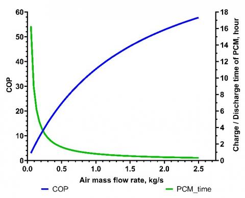
Figure 3 shows the impact of air mass flow rate on system performance. The COP of the system increases as the airflow rate increases, and the melting/solidification time decreases with higher airflow rates due to a more significant cooling/heating effect and better heat transfer rate in the APHX. Variable fan speed and dampers can regulate the airflow rate.
Figure 3. Air flowrate impacts the system performance, charging/discharging time
3.3 Water flowrate impact
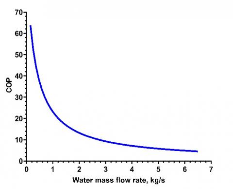
Figure 4 depicts the water flow rate impact on the system's performance. Increasing the water flow rate, the system's COP dropped dramatically due to excessive water spray compared to the cooling tower's airflow rate. The results specify that water flowrate less than 1kg/s is preferred. The water flow rate strongly depends on the airflow rate in the evaporation medium. Justifying the air-to-water ratio is crucial to optimizing the cooling tower's performance.
Figure 4. Water flowrate impact on system
3.4 Melting temperature of PCM impact
The system's performance is shown in Figure 5. Whereas the PCM melting temperatures rise, the supply temperature rises, but the system's COP falls due to the reduced cooling effect. The optimal PCM's phase transition will be between (27-31℃), providing the longest melting/solidification time (12 hours). The PCM with a melting temperature of 30℃ is recommended in literature to provide the best system efficiency, but it has difficulty providing thermal comfort [7]. The study shows the same result, but in this study, PCM RT21HC, whose melting temperature was 21℃, was used to provide thermal comfort.
Figure 5. Impact of PCM melting temperature on supply air temperature, system performance, charging/discharging time
3.5 Impact of mass of phase change material
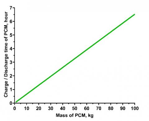
Figure 6 demonstrates the linear proportional relationship between PCM's mass on the melting and solidification duration. Due to the larger capacity of the APHX with a higher mass of PCM can absorb more energy and lasts longer to release and store. The figure also determines the system's required PCM capacity. The system can just work for 1.5 hours with 25kg of PCM RT21HC. Different PCM types have different heat storage capacities and thermophysical properties.
Figure 6. Impact of mass of the PCM on charging/discharging time
3.6 Impact of outdoor relative humidity
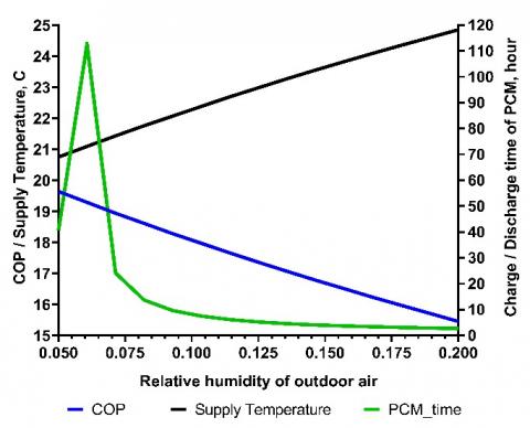
Figure 7 shows the impact of outside relative humidity on efficiency. The effect of outdoor air relative humidity on system performance is depicted in Figure 7. Low relative humidity of outdoor air has a greater ability to absorb evaporated water, thus leading to a better evaporation process in the cooling tower. The supply air temperature increase, and the COP of the system decreases at higher relative humidity due to lack of water evaporation. PCM's melting/solidification time depends on the temperature gradient between Air and PCM.
Figure 7. Impact of outdoor relative humidity on supply air temperature, system performance, charging/discharging time
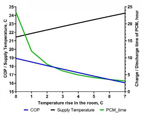
3.7 Impact of Room cooling/heating load (increase in room temperature)
Figure 8 depicts the influence of the cooling load in the building on system performance. When the cooling load increases, the system's COP decreases, and the supply air temperature rises because the warmer air supplied to the cooling tower and the cooling tower produces warmer water. The limitation of the cooling tower is the wet-bulb temperature of incoming air in the cooling tower. The melting/solidification time decreases as the cooling load increases because of a more significant temperature gradient among Air and PCM.
Figure 8. Impact of increased temperature of room on supply air temperature, System performance, charging/discharging time
3.8 Impact of air to water compact heat exchanger
The effectiveness of air to water compact heat exchanger on system performance is depicted in Figure 9. The supply air temperature is decreased due to better heat transfer among Air and PCM, and the system's COP is raised. The time required for melting/solidification will be dictated by the temperature gradient between Air and PCM.
Figure 9. Impact of temperature effectiveness of compact air to the water heat exchanger on supply air temperature, System performance, and charging/discharging time
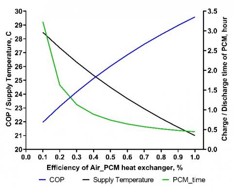
3.9 Impact of temperature effectiveness of the APHX
The efficiency of the APHX affects system performance, as seen in Figure 10. As the APHX's efficiency improves, the system's COP rises, and the supply air temperature decreases due to improved heat exchange for a higher temperature gradient among Air and PCM. Melting and solidification time is gradually lowered and substantially shortened because of a more significant temperature gradient among Air and PCM.
Figure 10. Impact of temperature effectiveness of APHX on supply air temperature, System performance, and charging/discharging time
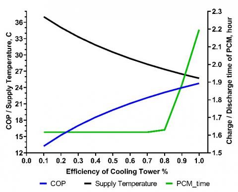
3.10 Effect of cooling tower efficiency
Figure 11 depicts the effect of cooling tower efficiency on system performance. As cooling tower efficiency increased, the supply air temperature decreased because of the system's enhanced cooling impact, and the cooling tower produced water at a lower temperature. As cooling tower efficiency improves, so does the system's COP. The melting/solidification time increases as cooling tower efficiency increases because of decreasing temperature gradient among Air and PCM.
Figure 11. Impact of cooling tower effectiveness on supply air temperature, system performance, and charging/discharging time
The proposed system consists of an indirect compact heat exchanger, APHX, and cooling tower. The study parameters that affect system performance are investigated in a hot and dry climate. Findings support proposed system can provide cooling and ventilation for buildings in hot and dry climates. Incorporating an APHX into the ventilation system improves thermal comfort by providing fresh air and adjusting the supply air temperature into the comfort range. In general, the proposed system has a high coefficient of performance and can save energy. The following are the main conclusions:
(1) In a hot and dry climate, the PCM cannot solidify at night unless evaporative cooling technology is integrated into the system.
(2) The APHX has low-temperature effectiveness of less than 20% due to low thermal conductance for both PCM and the air.
(3) Cooling tower efficiency significantly impacts the system's COP because it affects the evaporation process in the cooling tower and the temperature of the produced chill water.
(4) The effectiveness of a compact heat exchanger affects system performance because of improved heat transfer between incoming fresh air and chilled water produced by the cooling tower.
(5) The system performs better with high incoming air temperature and low relative humidity because of its high evaporation ability.
(6) The temperature gradient between Air and PCM determines how long it takes for PCM to melt/solidify.
(7) The cooling tower should adjust airflow and water flow rates to optimize system performance.
(8) This study recommends PCM with a melting temperature range of (27-31℃), which provides the best efficiency for the system and agrees with the literature. However, the system cannot provide thermal comfort air. To overcome this issue, PCM RT21HC was used in the current study to provide ventilated thermal comfort air.
(9) The proposed system can reduce supply air temperature by 2℃ by incorporating an Air-to-PCM heat exchanger with only a 20 Pa pressure resistance that does not increase power consumption.
|
C* |
The ratio of heat capacity |
|
$\dot{Q}$ |
Rate of heat transfer (W) |
|
$\dot{m}$ |
Air mass flow rate (kg. s-1) |
|
APHX |
Air to a PCM heat exchanger |
|
COP |
Coefficient of performance |
|
DEC |
Direct evaporative cooling |
|
EC |
Evaporative cooling |
|
EFCS |
Enhanced free cooling system |
|
FCS |
Free cooling system |
|
h |
Convective coefficient (W. m-2. C-1) |
|
HTF |
Heat transfer fluid |
|
IEC |
Indirect evaporative cooling |
|
LHTES |
Latent heat thermal energy storage system |
|
LMTD |
Log mean temperature difference |
|
NTU |
Number of a transfer unit |
|
PCM |
Phase change material |
|
TES |
Thermal energy storage |
|
A |
Area (m2) |
|
C |
Rate of heat capacity (W. C-1) |
|
Cp |
Specific heat (J. kg-1.C-1) |
|
K |
Thermal conductance (W. m-1. C-1) |
|
L |
Latent heat (kJ. Kg-1) |
|
R |
thermal resistance (m-2. C-1. W-1) |
|
Rh |
relative humidity (%) |
|
T |
temperature (C) |
|
U |
heat flow coefficient (W. m-2. C-1) |
|
W |
Humidity ratio (kgair .kgwater-1) |
|
m |
mass (kg) |
|
t |
Thickness (m) |
|
Greek symbols |
|
|
ε |
Temperature effectiveness, % |
|
Subscripts |
|
|
a |
Air |
|
HX |
Heat exchanger |
|
min |
Minimum |
|
s |
Supply |
|
w |
Water |
|
WB |
Wet Bulb |
[1] Yüksek, İ., Karadağ, İ. (2021). Use of renewable energy in buildings. Renewable Energy - Technologies and Applications, March. https://doi.org/10.5772/intechopen.93571
[2] Chel, A., Kaushik, G. (2018). Renewable energy technologies for sustainable development of energy efficient building. Alexandria Engineering Journal, 57(2): 655–669. https://doi.org/10.1016/j.aej.2017.02.027
[3] Sharma, A., Tyagi, V.V., Chen, C.R., Buddhi, D. (2009). Review on thermal energy storage with phase change materials and applications. Renewable and Sustainable Energy Reviews, 13(2): 318-345. https://doi.org/10.1016/j.rser.2007.10.005
[4] Ousegui, A., Marcos, B., Havet, M., Dardir, M., Panchabikesan, K., Haghighat, F., El Mankibi, M., Yuan, Y. (2019). Inverse method to estimate air flow rate during free cooling using PCM-air heat exchanger. Journal of Energy Storage, 22: 157-175. https://doi.org/10.1016/j.est.2019.02.011
[5] Verma, P., Singal, S.K. (2008). Review of mathematical modeling on latent heat thermal energy storage systems using phase-change material. Renewable and Sustainable Energy Reviews, 12(4): 999-1031. https://doi.org/10.1016/j.rser.2006.11.002
[6] Ding, J., Zhang, H., Leng, D., Xu, H., Tian, C., Zhai, Z. (2022). Experimental investigation and application analysis on an integrated system of free cooling and heat recovery for data centers. International Journal of Refrigeration, 136: 142-151. https://doi.org/10.1016/j.ijrefrig.2022.01.003
[7] Waqas, A., Kumar, S. (2011). Utilization of latent heat storage unit for comfort ventilation of buildings in hot and dry climates. International Journal of Green Energy, 8(1): 1-24. https://doi.org/10.1080/15435075.2010.529406
[8] Liu, Z., Yu, Z., Yang, T., Qin, D., Li, S., Zhang, G., Haghighat, F., Joybari, M.M. (2018). A review on macro-encapsulated phase change material for building envelope applications. Building and Environment, 144: 281-294. https://doi.org/10.1016/j.buildenv.2018.08.030
[9] Xiong, Q., Alshehri, H.M., Monfaredi, R., Tayebi, T., Majdoub, F., Hajjar, A., Delpisheh, M., Izadi, M. (2021). Application of phase change material in improving trombe wall efficiency: An up-to-date and comprehensive overview. Energy and Buildings, 258: 111824. https://doi.org/10.1016/j.enbuild.2021.111824
[10] Aneli, S., Arena, R., Gagliano, A. (2021). Numerical simulations of a PV module with phase change material (PV-PCM) under variable weather conditions. International Journal of Heat and Technology, 39(2): 643-652. https://doi.org/10.18280/ijht.390236
[11] Issa, R.J., Manla, E. (20