Sarah A. Abbas* | Adel A. Eidan | Assaad Al Sahlani
© 2022 IIETA. This article is published by IIETA and is licensed under the CC BY 4.0 license (http://creativecommons.org/licenses/by/4.0/).
OPEN ACCESS
This research paper presents a detailed review of the recent advances concerned with carrying out efficient solar chemical reactions by reviewing the most recent reactors available in the literature that use solid-gas reactions or pyrolysis processes. Major research groups in solar chemistry design and manufacture a wide range of solar reactor configurations, widths, and sizes, including directly radioactive particles. Solar reactors heat up to 1000℃ and can be utilized to store chemical thermal energy in concentrated solar power facilities (CSP). Reactor efficiency is better in bed reactors notably in rotating pyrolysis, fluidized bed reactors with solid gas, and fixed-bed reactor systems. Finally, their description, schematics, and key performance parameters are presented for chemical reactions.
solar reactors, high temperature, solid-gas reactors, particle receivers
It is possible to use solar energy at high temperatures in thermochemical reactions that use heat. As an alternative, solar fuel, which is a granular chemical state, can be used to store long-term endothermic processes in solar reactors, allowing for the storage of solar energy in the form of solid media.
The researcher Asaad et al. [1] studied the experimental, numerical, and simulation system for temperature regulation inside the reactors in the component flow for thermochemical energy storage applications, and the simulation results showed good agreement with those obtained from the experiments. Hrenya et al. [2] created a multi-stage prototype to calculate the transfer of non-radiative heat from liquid materials to solid materials inside a heated solar tube. The results appear in good agreement with the DEM simulation data. These results provide critical observations about the efficiency and feasibility of different designs.
Roy et al. [3] This researcher used a numerical model based on the liquid volume method to model evaporation resulting from reproduction. The study showed a high increase in the distribution of liquids with an increase in the density of water mist to avoid blockage by making sure that water vapor is evenly distributed in the opposite gas stream. The outstanding results achieved using removal values are crucial in the numerical investigation of counter-current flows.
A simple model for conductive heat transfer between moving particles in a liquid was used to obtain the Nusselt number and heat transfer coefficient [4]. When compared to actual values, the model's predictions are within 7% of what was found using DEM data.
Auerkari [5] designs the properties of alumina porcelain materials so that the parameters and results of the VTT project, which aims to improve joints with a single component, made of alumina ceramics with an engineering degree to control the residual stresses in the production of high-performance dissimilar links for industrial and energy applications, can be determined by high temperatures.
An active mobile heat exchanger (MBHE) was theoretically studied by this researcher, and the numerical outcomes demonstrate that high efficiency is harmed by solid conductivity of heat exchangers with temperature differences inside of the solid particle flow downward and recover heat from the gas flow with filtering of solids in the tangential flow [6]. A two-dimensional model is used to calculate the packed bed's effective heat transfer coefficients at temperatures ranging from 800 to 1100 degrees Celsius under constant circumstances, and the results show that the calculated effective coefficients are in agreement with those obtained in an experimental study conducted in a solar tube reactor heated by an electric furnace for manganese iron oxide particles [7]. Effective thermal conductivity temperature is in good accord with the correlations published elsewhere.
Tuttle et al. [8] Thermal conductivity inside particles was calculated using a simulation model, which was validated using a new model and temperature measurements throughout the device, as well as a reactor with a packed bed for storing thermal energy. The appropriate thermal conductivity was found to be able to achieve these calculations in this research. An 87 percent improvement over the current literature with accurate temperature forecasts can be attributed to the outcomes of this study. In the study of ref. [9], a new class of easily flowable particles is produced and tested through hundreds of oxidation-reduction cycles to demonstrate great storage capacity, physical strength, and chemical activity. Results of spray-dried particle durability during the oxidation-reduction cycle reveal that the activity and thermal performance of the particles work well in this reaction.
Andre et al. [10] have shown that SO3O4 raw material in terms of kinetics and efficiency full reversal to enhance reactions in this experimental study. The results show that materials' interactions can be improved in terms of thermal performance and enhanced for solar thermal energy storage through this experimental study. Farcot et al. [11] use an experimental and analytical study, this researcher determined to know the effect of air humidity at the inlet of the moving bed reactor and that the bed reactor performed well in terms of achieving a stable temperature and distributing the temperature evenly throughout the bed.
According to Chueh et al. [12] and Furler et al. [13, 14], the solar reactor is detailed in-depth about its design and dimensions. Mechanical and process engineering researchers at ETH Zurich took the measurements that are being used as a standard for comparison. This section provides an overview of the many solar reactor configurations. It was used to model a CSP system that utilizes an array of high-flux solar simulators coupled to truncated ellipsoidal reflector Xe-arc lamps (HFSS). When it comes to receiving a large amount of radiation, the cavity receiver is where most of it lands. Increased concentration ratio and reduced reradiation losses are achieved by connecting the CPC's 4 cm inlet aperture to the cavity exit. receiver's A fused quartz window with a diameter of 24 cm and a thickness of 3 mm seals the reactor's aperture. To keep the temperature stable, the CPC and cavity receiver were both water-cooled. The ceria RPC cavity-receiver of the solar reactor is spherical and exposed to intense solar radiation. Inconel 600 is used to build the cavity-receiver wall, which is insulated with Al2O3. A thin layer of ceria laminate is sandwiched between the ceria RPC and the Al2O3 insulation. There were four radial intake ports near the window aperture and the annular gap between the RPC and ceria layer that had to be filled with argon gas. The product gas is expelled through an axial output port on the bottom of the receiver. Solar power is used to pre-heat the ceria RPC to around 1000 K. Preheating allows for lower temperatures to be achieved. Thermal reduction of RPC ceria can be used to separate H2O and CO2 from RPC ceria [12, 13]. An oxidation step follows the reduction step, and this one does not require any solar energy. Three different solar power inputs are used to examine oxygen production and efficiency during a reduction in the lab. There is an oxidation step that does not require solar energy after the reduction process. Three different solar power inputs (2.8 kW, 3.4 kW, and 3.8 kW) are used to examine oxygen production and reduction efficiency. This stage of reduction is the focus of the current numerical investigation [13]. The smallest dimension of the ceria RPC use L = 20 mm and its extinction. coefficient being k = 500 mm-1, the optical thickness τ of the porous rector is 10, i.e., (τ = k×L), which is much greater than unity.
Particle receiver research aided in the development of the first receiver-reactors, which combined the functions of a heat absorber and a chemical reactor. There are a variety of ways that particles can be placed within a reactor, depending on the amount of time they need to spend carrier fluid. These characteristics have a direct effect on how heat and mass move. According to Villermaux et al. [15] particles of solar reactors can be divided into entrained, fluidized, and stacked reactors, which are all types of reactors particles see (Table 1). The entrained type reactors should include falling particle cloud solar reactors, such as the receiver described earlier-if it had a chemical suggestion. The type of application may profoundly influence the choice of a particles solar reactor. For solar catalytic reactions, Villermaux et al. [15] advocated the use of fixed beds, which are part of the stacked reactors group. He recommended using fluidized beds for reactions that needed strong thermal transfer qualities. Homogenous heating of the reaction medium is encouraged by the close contact between the gas and the fluidized particles. In addition, the temperature is likely to rise significantly. Depending on the sub-type of entrained reactors, he has a different proposal. Cyclones, for example, are interesting if you want to further separate solid and gas. Rotating kilns, according to Villermaux, are of particular importance because of the wealth of knowledge and experience that has already been gained in the field of solid treatment using these reactors. The categorization of solar reactors may have been done differently. It's one of the options that other authors have taken into consideration. Solar reactors for the gasification of carbonaceous feedstock have been studied by Steinfeld [16] and Puig-Arnavat et al. [17] according to a 2012 study on solar reactors at the state of the art. There have been several prototypes for particle solar reactors since the first investigations began. As a compilation, this one does not always adhere to Villermaux's selection criteria; but the entrained, fluidized and stack reactors are distinguished.
Table 1. Gas-solid reactors are included in the table according to Villermaux [15]
|
Beds that are fluidized or suspended |
Pulsed or vibrated Fluidized bed A fluidized bed that circulates Bed blown A drooping bed |
|
|
Beds stacked |
Fixed \Mobile the oven that has been brewed |
Conveyor belt, Rotary kiln, and Multistage Blast furnace |
|
Beds that are entrained |
Pneumatic transportation Particles falling from a cyclone |
|
3.1 Reactors that are entrained
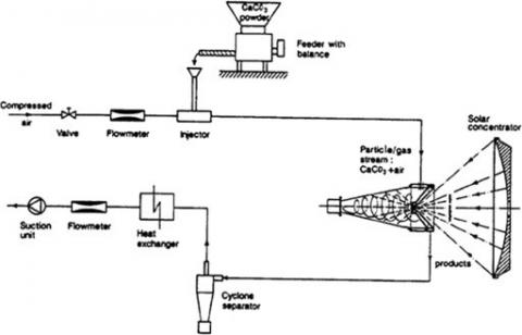
CNRS-ENSIC chemical engineers in France [15] were working on an innovative particle solar reactor concept at the same time that SNL was developing the initial SPCR concepts. At 1143 K, continuous flash pyrolysis of wood sawdust was to be examined. The results showed that a reaction of this magnitude might be carried out on a huge scale in a new type of reactor using concentrated solar energy. Gas–solid thermochemical reactions were the focus of a new solar cyclonic reactor proposed in 1991 by Granqvist et al. [18]. This approach combines the benefits of volumetric receivers, such as strong radiation absorption, with an efficient mechanism to continually feed reactants and remove products [19]. Figure 1 depicts the cyclonic reactor, a 30 cm in height truncated conical cavity that was the atmosphere to opened. made of DIN-1.4435 steel, 10-deg cone opening angle, major circular opening of 20-cm diameter, 3-mm thickness. The walls have been insulated with a 12-cm thick layer. A ceramic insulation layer was applied to the interior walls to keep them warm. For the gas exhaustion, the rest of the hollow was produced by two concentric cones. The reactor was designed for use in the PSI's 17 kW solar furnace. As an illustration of a gas-solid reaction, the authors looked at the heat breakdown of calcium carbonate. A heat exchanger was used to cool the exhaust gas stream from the solar reactor, and a cyclone separator was used to remove the solid products from the gas stream. Temperatures were recorded to be around 1350 degrees Fahrenheit, with an overall efficiency of 43%. On the basis of how much energy is absorbed, including sensible and process heat, this efficiency is calculated. a second prototype was built and tested at 55 kW according to Steinfeld et al. [19] in a dish with the same layout but greater dimensions.
By adding a vortex flow into a solar cavity receiver in 1998, Steinfeld et al. [20] constructed a solar chemical reactor that was more efficient. A 5 kW SynMet prototype was built and tested at PSI's solar furnace. As raw materials, ZnO and natural gas were used to make metallic Zn and syngas (NG). A quartz window adorned a cylindrical cavity within the device. The reactants and the walls of the hollow were heated by focused radiation that came through the window. A tangential inlet was used to continuously inject ZnO particles into the cavity, which were then carried along in a flow of NG. Vortex flowed from the reactor's back end to its front end. Chemical conversion from ZnO to Zn reached a 90% efficiency at 1600 K. An innovative feature of this reactor was the use of an actively cooled window. At the window, the second stream of gas was introduced in two directions: tangentially and radially. Cao and syngas were then produced using a combination of CaCO3-decomposition and CH4-reformation processes in this reactor according to Nikulshina et al. [21] similar to SynMet's reactor, the SYNPET reactor (2003-2009) was used to steam-gasify petcoke. Following several failed attempts by Z’Graggen et al. [22, 23], a slurry generator was selected as the primary reactant feeding system. High-flux solar furnace temperatures of 1300 to 1800℃ were used to convert up to 87 percent of the petcoke. When the product sensible heat was not taken into consideration, the efficiency of solar-to-chemical energy conversion was just 9 percent. The efficiency of steam generation and pre-heating increased by 20 percent when sensible heat was recovered. From 5 to 300 megawatts was the size of the vortex reactor later, Blanco et al. and Graggen et al. [24, 25], they suggested that increases in volume and surface area increased efficiency by 24 percent. The results were shown to be significantly affected by particle size conversion and reactor residence duration. Figure 2 depicts two different designs for 5 kW reactors, one from 1998 and the other from 2006. New solar cyclone reactors to perform methane thermal splitting were developed by Weizmann Institute researchers. To ensure that the reactor was completely free of carbon particles, this configuration was chosen. A tornado flow in a seed reactor with a clear window was therefore shown to be helpful as suggested by Kogan et al. [26]. There was a maximum of 28.1 percent of reaction reported at temperatures of 1320 K. The reactor walls and the exit port were found to have a high level of carbon deposition, which frequently resulted in the termination of an experimental study. Because methane splitting generates carbon particles in the chamber's center rather than its walls, this decision was made.
Figure 1. Pre-Steinfeld cyclonic solar reactor and experimental setup [19]
Figure 2. The left are prototypes for ZnO reduction using NG [20]; On the right, is a properly developed prototype for petcoke steam-gasification [23]
Kogan et al. [27] suggested the use of radiation-absorbing particles to seed the reaction chamber. The temperature in the center of the cavity was raised in this manner. However, it was imperative that the reaction window be protected from incandescent solid particles. The design of the reactor was analyzed using a variety of geometries. It was, however, imperative to keep the reaction window safe from incandescent solid particles. Engineers looked at various reactor designs to find the most efficient one. Figure 3 depicts the most recent proposed geometry, which was deemed adequate. The reactor's core was divided into three pieces. Main gas streams were injected through a distributor situated at the reactor's apex to generate a tornado-like flow pattern inside the reactor chamber. Two extra the seeding gas can be injected into one of the three lateral ducts placed between the segments (d1, d2, or d3). In 1994, Alonso and Ganz et al. [28, 29] presented a novel reactor design based on the notion of absorbing solar direct radiation by a cloud of particles. It was a cylindrical steel container with a windowless aperture inside. A swirling air stream carried the powdered reactants to the cone. They were exposed to a high level of solar radiation. To keep the particles from escaping the reactor, a radial air jet was employed. Thermally quenched reactants exited through a cooled axial tube. Figure 4 depicts a diagram of the solar reactor. Because many thermochemical processes need solid particle heating in the region of 1300-1800 K, vortex-flow reactors are a potential choice (for solar fuels production, thermochemical storage, etc.). The main considerations for a properly designed prototype are the cavity's geometry and the injection of gas and reactants.
Figure 3. Proposed geometry and proper tornado flow show to prevent window damage according to Kogan et al. [27]
Figure 4. Solar reactors were proposed by Meier et al. [29]
3.2 Reactors that use fluids
Fluid beds provide two benefits over entrained reactors: improved gas-solid interaction and longer particle residence time. There are some advantages to this, such as chemical reactions with slower kinetics, to this feature. Flamant et al. [30] came up with the idea of a solar fluidized bed in 1980. Between two metal brackets was a 34 mm diameter transparent silica tube. The tube was irradiated with concentrated sun radiation Figure 5. Using this device in a 2-kW solar furnace, thermal treatment of refractory materials "600-1300℃" and decarbonization of calcite (850℃) were both effectively done. Graphite particles were attached with calcite in order to increase the chemical rate.
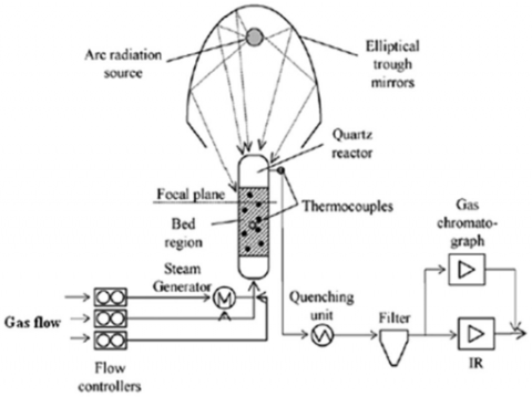
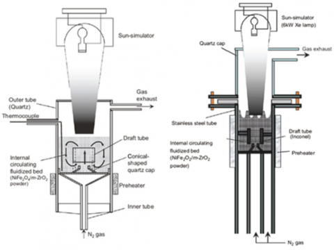
The thermochemical conversion was also improved with graphite upper to 14%. The reactor was scaled up to 50 kW by Flamant et al. [31]. Later refinements offered by Sabatier, Paul, and others [32] design included an opaque fluidized bed with a clear window on top or an annular fluidized reactor with opaque external walls that are likewise irradiated from the top. Due to their simple construction and operation, fluidized beds are frequently used for preliminary thermochemical tests in the laboratory. The ZnO reduction and CH4 reforming are shown in Figure 6 by Steinfeld et al. [33] in a small solar fluidized reactor. A quartz tube with a diameter of 2 cm was used to construct it. A CPC and an involute were used to consistently irradiate the tubular reactor. This arrangement was responsible for the design's thermal efficiency, low thermal capacitance, and superior thermal shock resistance. The ZnO particles were dissolved in CH4, and the reaction was triggered by the high-intensity sunlight from the solar furnace. The fluidized bed was expected to be at a constant temperature as long as it was bubbling furiously. The reactor-receiver displayed low thermal inertia, strong thermal shock tolerance, and a high degree of thermal stability for direct absorption operations. In the decreased gas, approximately 43% of the CH4 was transformed into CO2. Nikulshing et al. [34] indicate a similar design was utilized in 2009 to execute consecutive CaO-carbonation and CaCO3-calcification to absorb CO2 from the environment, as shown in Figure 7. In the solar reactor, a fluidized bed of reacting particles was confined in a quartz tube with an outside diameter of 25 mm and a height of 25 cm. 75 kW of electricity was applied to the tube's top using a high flux solar simulator. The simulator's focus point was in the middle of the fluidized bed. After five successive cycles, a CO2 mass balance of close to 99 percent was attained. Temperatures as high as 1150 K were obtained during the calcination process. Gokon et al. [35] presented a novel solar fluidized bed. The sun's rays streamed through a top-mounted glass in the reactor, directly heating an internal circulating bed of reactant particles. They concentrated on a NiFe2O4/m-ZrO2 two-step thermochemical cycle. Based on this notion, two laboratory reactors in Figure 8 were created and evaluated using a 6 kW Xe-arc solar simulator. The power input utilized was between 2.4 and 2.6 kW. The original one was made of quartz tubes and had a 45 mm outside diameter. The carrier gas was introduced into the bed using a conical cap and a draft tube. At 900 degrees Celsius, the reactor was warmed. As a backup, a stainless steel fluidized reactor was developed with approximately identical dimensions. A quartz window was built at the top of the reactor to allow focused radiation to enter. It was discovered that a draft tube in the reactor design, which provides internal circulation, increased chemical conversion. Furthermore, according to Gokon et al. [36], the stainless steel prototype performed better, probably due to the opaque walls' increased thermal efficiency. It was then employed in the stainless steel reactor to accomplish both heat reduction and water decomposition processes, commencing with NiFe2O4 and m-ZrO2 particles. In thermal decomposition, inert gas was replaced with an inert gas and steam combination as the gas input; in water decomposition, inert gas was replaced with an inert gas and steam mixture as the gas feed. With an incoming power supply of 1.6-1.7 kW, the second reaction took place. Hydrogen was successfully produced using a chemical conversion rate of 45 percent and a maximum temperature of 1200 degrees Celsius. Several authors have investigated solar gasification in a fluidized bed reactor. This is the case with the down irradiated fluidized bed idea developed by Puig-Arnavat et al. [17], which was effectively employed to gasify coal coke. According to one source, it has a maximum energy conversion efficiency of 14 percent. In their study, both ETH and the University of Minnesota employed fluidized beds for sun gasification of carbonaceous material [17].
Figure 5. Lab-scale fluidized bed scheme Flamant et al. [31]
Figure 6. Proposed the solar fluidized bed by Steinfeld et al. [33]
Figure 7. A fluidized solar reactor was tested in the PSI high flux solar simulator and the process was set up [34]
Figure 8. Depicts internal circulating fluidized solar reactors by Gokon et al. [35]
3.3 Reactors stacked
A difference between fixed, mobile, and rotating kilns should be established by Villermaux [15] in his categorization. For mass and heat transport, rotary reactors have been proven to be preferable in general A fixed reactor is often less difficult to design, build, and operate than a fluidized bed reactor (FBR). Fixed-bed prototypes are common laboratory instruments for exploring chemical processes in modest and preliminary forms.
3.3.1 Fixed-configuration reactors
Fixed reactor TREMPER was developed by Alonso et al. [28] to investigate the chemical kinetics of reactions at temperatures up to 2100 K. All of the components that made up TREMPER were contained within a quartz tube in Figure 9. Copper support was used to cool the sample, which was inserted into a small hole. The sample was not able to react with the support because of this arrangement. For the concentrated solar radiation to reach the sample, the 45° mirror used was used to direct it. A silica capillary was inserted into the quartz tube to capture the carrier gas. A gas flow was directed toward the mirror to keep it from evaporating. The outlet was fitted with a cooling mechanism. Using results from an earlier investigation of flow patterns by Frey et al. [37] which demonstrated that the entire apparatus behaved like an optimally stirred continuous tank, online gas measurement at the outlet could readily calculate gas release rates. To decrease iron and manganese oxides, TREMPER was utilized, with 25 percent of the iron oxide and 85 percent of the manganese oxide attaining their maximal chemical conversion rate. Alonso and colleagues also studied the 1 kW solar reactor's thermal reduction of non of non-volatile metallic oxides [28]. The solar reactor is seen in Figure 10 in its schematic form. The 100 mm high and 80 mm in diameter tank was sealed from the outer world with stainless steel and quartz windows. A 45°-sloped water-cooled mirror uses radiation from a 7 kW solar simulator to send concentrated solar radiation into the reactor's cavity. Adding samples one at a time to a thick bed of particles. The reaction chamber was swept and gas products were collected by introducing a carrier gas into the chamber. An ideal plug flow was observed in the reactor's inlet. Mn2O3 and Mn3O4 manganese oxides were reduced in the packed-bed top layer, with a maximum conversion of 60% for Mn2O3.
Figure 9. A rear view of TREMPER [37]
Figure 10. A vertical solar reactor that generates 1 kW of power by the Alonso et al. [28]
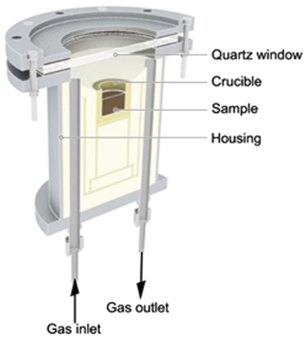
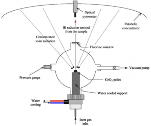
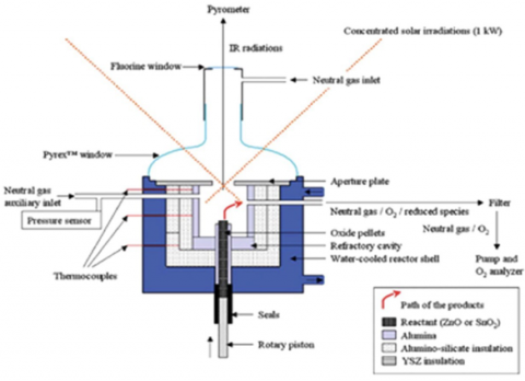
A maximum temperature of 1400C was measured at the top of the sample. However, high thermal gradients were produced between the irradiated surface and the bottom of the sample. Similar flow pattern characterization as well as thermal tests was done on a novel 2 kW prototype designed by Alonso et al. [28] (Figure 11). The primary component of the solar reactor was a 110 mm long and 60 mm wide alumina cavity, which was surrounded by an alumina cone and covered on the back by an alumina cover. The gas outlet was installed. A quart-sized water-cooled window was included in the cone. Insulation was used to separate the stainless steel housing from the cavity. Four perforations in the cross-section of the frontal cone were used to introduce gas. As soon as it had crossed the reactor's interior, it exited through a duct at the reactor's rear. The reactants were kept in the center of the cavity in a cylindrical ceramic sample holder with an inner diameter of 20 mm and an outer diameter of 26 mm and a length of 50 mm. Radiation was permitted to enter through a quartz window and an aperture. Particularly at high temperatures and high gas flow rates, fluid flow behaved like an ideal Plug Flow Reactor." A 47 percent effective thermal efficiency was attained using 530 W of input electricity. There were large thermal gradients in a sample that had a maximum temperature of 1450℃. Reductions of Mn2O3, Mn3O4, and CeO2 were carried out, with the first one achieving a complete conversion and the rest varying depending on the reaction conditions Pre-sintered ZnO was also dissociated in fixed reactors by Moller and Palumbo [38] and Keunecke et al. [39] depicts the reactor's schematic layout in Figure 12. Stabilized ZrO2 insulation was used to line the reactor chamber. At the focal point of the solar furnace, a cylindrical pellet of ZnO was inserted in a ZrO2 receptacle Sunlight passing through the window focused on the ZnO front surface. Several inert gas streams were used to keep the vapor from condensing on the glass. Through a chimney, the reaction products and the inert gas exited the reactor and entered a heat exchanger. The sample was capable of reaching 2100 K. Condensed solar energy may be utilized to heat a reaction pellet to better comprehend the reduction stage of the CeO2-based water splitting thermochemical cycle, as demonstrated by Abanades and colleagues [40] that using a PyrexTM spherical vessel, concentrated solar energy could be used to heat a reaction pellet to better understand the reduction step of the CeO2-based water splitting thermochemical cycle. In Figure 13, it is depicted. This type of solar reactor was airtight and could run in a variety of different environments, including vacuum, inert gas, or reactive gas. As shown by the findings, Ce (IV) to Ce (III) may be totally reduced to Ce (III) utilizing the right parameters, such as beginning sample mass, reaction time, pressure, and temperature.
Figure 11. Reactor schematic section who developed it Alonso et al. [28]
Figure 12. Fixed reactor for ZnO dissociation from before Moller and Palumbo [38]
Figure 13. Solar reactor for reducing CeO2 in a controlled environment by Abanades and Flamant [40]
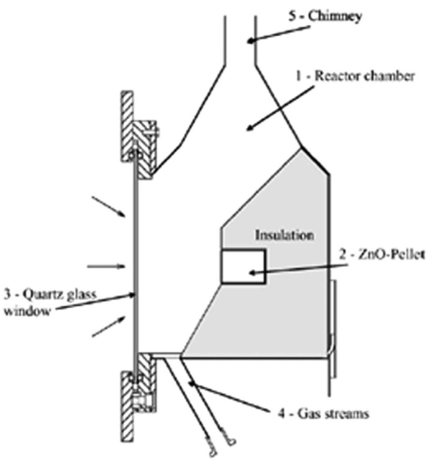
The surrounding gas flow's hydrodynamics also had a part in the excellent outcomes. Temperatures of 2000℃ were discovered during the melting of CeO2 in the sample. During post-treatment characterization, the sample's large thermal gradients were detected. Chueh et al. [12] suggested the solar thermochemical H2O–CO2 splitting cycle using cerium oxides as well. In this scenario, fixed solar reactors were utilized to complete two stages of a cycle, one at a greater temperature and the other at a lower temperature Figure 14 shows a schematic of the solar gadget. Porous monolithic cerium cylinders were encased in a thermally insulated cavity receiver. Through a windowed hole, the interior walls of Ceria received concentrated solar radiation. While reaction gases traveled radially into the cavity, product gases escaped through an axial port at the bottom of the porous ceria. To demonstrate the complete cycle's viability, CO2 and H2O were dissociated. As a consequence, CO and H2 were produced consistently and quickly. Over 500 thermochemical cycles, the material's stability was also demonstrated. Only efficiencies of 0.7–0.8 percent were achieved in solar-to-fuel conversions. It's been suggested that thermal transfer is in charge of regulating the process's high-temperature stage. Furthermore, low productivity was also cited as a factor in thermal losses limiting the system's size and design. As a result, reactor optimization became necessary. For the two-step thermochemical water splitting cycle, Chambon et al. [41] explored ZnO and SnO2 thermal reactions in a solar fixed reactor. Incorporated a stainless steel water-cooled cylindrical body "76 mm deep, 88 mm wide". A Pyrex TM convex window kept it close to the outside. Internally, the cavity was insulated with ceramic coating. This reaction was carried out in a ceramic tube that was seven millimeters (0.7 inches) high. Continuous reactant injection could be achieved by pushing the rod up via a screw piston that was manually rotated. The cavity reached temperatures of 1900 K. ZnO and SnO2 dissociation kinetic parameters were determined. Despite the poor yield (about 2%), researchers intended to enhance the findings by tweaking a quenching mechanism at reactor output. This reactor is depicted in Figure 15. The Tokyo Institute of Technology came up with a new design for a solar fixed reactor after experimenting with a new concept (Japan). It was intended to create hydrogen from the sun using a two-step water-splitting process. Water splitting and oxygen discharge took place in separate reactor rooms. The reactor itself had two reaction chambers in total. A rotor was used to spin these two reaction chambers. The reactor was rotated so that the concentrated solar radiation was alternated between the reaction cells.
Figure 14. A Diagram of the solar reactor is proposed for the investigation of the thermochemical H2O–CO2 split-cycle [12]
Figure 15. A fixed solar reactor was built to investigate the high-temperature thermal reaction of ZnO and SnO2 according to Chambon and colleagues [41]
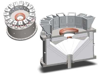
Figure 16. A new solar reactor has been developed by the Tokyo Institute of Technology [42]
Two-stage water-splitting solar furnace is depicted schematically in Figure 16 according to suggestions Kaneko et al. [42]. Experimental work was done by Kaneko et al. [43] in a laboratory reactor with an infrared lamp to conduct two thermochemical cycles, one for CeO2 and the other for Ni, Mn-ferrite. In each water splitting and reduction cell, the H2 and O2 evolution was observed to be successively repeated in the two stages of the two processes. In the case of the CeO2 cycle, the optimal reaction temperatures were 1623 K and 1273 K, and 1473 K and 1173 K, respectively. According to CSIRO's plans, the reactor would have been put into operation with an output power of between 10 and 30 megawatts (MW). Asia-Pacific Partnership on Clean Development and Climate was the framework for this project. SNL came up with another concept as a result of the rotating reaction cells. Ferrites thermochemical cycles were the primary goal according to Hogan et al. [44]. Formed from a stack of counterrotating disks or rings, the CR5 was known as the Counter-Rotating-Ring Receiver/Rector/Recuperator. The fins contained ferrite reactant, most likely on a supporting surface. One RPM or less was required for each ring to rotate in the opposite direction of its neighbor. The fins on the stack of rings on the edge were illuminated by solar flux along approximately one-quarter of the perimeter. The water oxidation reaction occurred on the other side of the stack. For counter-current recuperation, thermal radiation is primarily used in the remaining half of the stack (two-quarter sections in between). Recuperator sections are kept as small as possible by maintaining equal pressures in both reactors as depicted in Figure 17, counter-rotating rings can be seen in detail in the CR5. Despite the fact that preliminary data on thermal efficiency varies depending on operating temperatures and the irreversibility of internal processes, the company reported a figure of 29.9 percent. In the process of reducing FeO, a maximum temperature of 2300 K was reported. For the gasification of carbonaceous material, Gregg et al. [45] proposed a packed-bed gasifier. In Figure 18 it is depicted the L-shaped reactor is made of stainless steel pipe (30 cm in internal diameter). Gravity is used solely in this method of feeding. A firebrick liner insulates the walls. A silica window with an aperture is put on the short side of the L. This permits sunshine to enter. Through the inlets around the window, steam or CO2 was poured into the reactor, and the exit was located on the reactor's top wall. With a maximum solar power input of 23, this reactor was utilized to execute gasifications of coal, activated carbon, coke, and biomass. The rate of CO2 gasification rose with an increase in solar power, and the composition and heating value of the gas was nearly independent of solar power when steam was utilized for gasification. There was a broad range of variance in the efficiency of solar power conversion from 19 percent to 48 percent. Smaller windowed packed-bed type solar gasifiers have been developed in a 2 kW solar furnace by Taylor et al. [22]. The reactant was heated by solar light while carbonaceous material was supplied into an insulated central body. Carbon gasification with steam obtained a 30 percent efficiency in energy conversion, whereas charcoal gasification with CO2 reached a 40 percent efficiency. However, utilizing a fluidized bed reactor, only 10 percent efficiency was attained for charcoal gasification with CO2. To begin an examination, it is usual practice to create a tiny reactor that can be quickly rectified. As well as providing for the measurement of reaction parameters like temperature or the study of the interaction between reactants and radiation, these reactors are relatively easy to build and run. If the reactor design and the process line into which it is integrated are adequate, parametric analysis and kinetic studies can also be established (correct flow path, gas concentration measurement, etc.) (proper flow path, gas concentration measuring, etc.). Thermal gradients are more prevalent in samples of the packed-bed type. Even while the surfaces exposed to the radiation can attain extraordinarily high temperatures, the sample as a whole cannot reach reaction temperature owing to limits in heat transmission. Chemical conversion and overall efficiency are degraded as a result of this.
Figure 17. The set of counter-rotating rings as shown in detail on the left. The solar reactor's general design is on the right [44]
Figure 18. packed-bed type gasifier was depicted in the publication by Gregg et al. [45]
3.3.2 movable reactors
A notable example of a transportable reactor is the GRAFSTRR reactor developed by Koepf et al. [46, 47]. In 2012 when it was built, it was designed to minimize Zn power. A rotating reactor-like dispersion of reactants would be possible but without the related challenges. An inverted conical reaction surface, enclosed by a quartz window, is used in the reactor to conduct a high-temperature thermochemical reaction with the reactant powder, which travels constantly as a moving bed.
Al2O3 (99.9%) trapezoidal tiles (300 mm long with an average width of 50 mm, and 12 mm thick) are supported by three layers of porous ceramic insulation, with primary composition Al2O3eSiO2 (w80 percent e20 percent) that are shaped into a 40-inclination. Gravity holds the cavity in place without the use of adhesives thanks to the interlocking symmetric geometry. It is expected that the reactor depicted in Figure 19 will operate at a power level of 10e20 kW or more. Moving-bed reactive layers are created by feeding ZnO powder to each tile surface individually. After the dissociation process, the Zn product vapor is directed downward towards a centrally placed outlet due to a vortex flow that begins above the aperture plane and links the reaction chamber to the exit tube. As seen in Figure 19 the reactor will run at a power output of around 10 - 20 kW. One method used to show the reactor and main system mechanical stability was particle entrapment in vortices and the adherence of moving beds to reaction surfaces. Temperatures on the reaction surface were observed to range from 1100 K to 1900 K.
Figure 19. Cross-section of GRAFSTRR reactor
3.3.3 Reactors that rotate
Cement and plaster production, food processing, and calcination of solids are just a few of the applications for rotary kilns. A rotary kiln generates a lot of heat and mass, which leads to a lot of chemical conversions. Its versatility, long component life, and low maintenance costs also make it an attractive option. According to Alonso et al. [28] however, this type of reactor necessitates a large amount of energy, which was formerly provided by fossil fuels. Such a problem can be addressed if concentrated solar energy is employed as a heating source both the solar radiation and the reactor's internal endothermic process must be coordinated. A theoretical model was devised by Sammouda et al. [48] to analyze heat transmission in the solar and infrared spectrums. Several design factors such as carrier gas mass flow rate, focused solar energy, inclination angle, and rotational velocity might be optimized thanks to the results obtained from this research project. Flamant et al. [31] used a solar-feed configuration in their experimental rotary kiln, and the findings were compared to those achieved in this work. Experimental and theoretical forecasts were able to keep temperature profiles and output temperatures from differing more than 5% or 10%. This water-cooled solar reactor was constructed by Flamant and his colleagues by employing refractory layers as well as insulating [31]. The device's constant rotating velocity was used to calculate the residence time for reacting particles. Thermal gradients of 100℃/cm were found in the tube. As previously mentioned, Flamant performed calcite decomposition and compared its findings to the fluidized-bed method. Using the rotating reactor, the greatest temperature reached was 1500 degrees Celsius, with a thermochemical efficiency of 30%. Flamant's rotating reactor is shown in Figure 20. Two solar prototypes based on the performance of a traditional rotary kiln have been identified in the literature. An Italian business called QualiCal Srl and PSI-ETH researchers created a 10-kilowatt rotating reactor in 2004 for the calcination of calcite to make lime according to Meier et al. [49]. Figure 21 depicts an open-air kiln with a 600-mm-long and 350-mm-diameter diameter that was horizontally operated, as indicated. An angle of 5° degrees was established in the reaction chamber. A beam of focused solar radiation was directed into a conical reaction chamber's preheating zone and a high-temperature discharge zone through an opening in the middle of a water-cooled aluminum front shield. The insulating and refractory material was contained in a stainless steel cylindrical drum. At all times, the reactor was running at maximum efficiency. The raw material was kept on top of a hopper at the reactor's back. A rudimentary discharge mechanism under the front plate gathered the finished product in open-air bins. Four rubber wheels on a circular swing were driven by a tiny electric motor. For the first time, a solar lime reactor ran for over 100 hours in 24 days of sunshine. At 1423 K temperatures, more than 98% of the calcination occurred. Some mechanical faults have been noted as a result of problems with internal refractory material resistance. The conversion of solar energy into chemical energy has reached a 20% efficiency level. It was also proposed that the reactor be improved to boost its efficiency a rotary reactor for thermal reduction and oxidation of cobalt oxide was created by the researchers of Neises and colleagues [50] plates of ceramic fiber were used as thermal insulation in place of siliconized silicon carbide cavities. The aperture was maintained closed against the heat of the sun using a quartz pane as a shutter. A secondary concentrator installed in front of the kiln directs solar radiation into the rotating kiln chamber. The reactor, which is powered by an electric motor, rotates on a set of wheels thanks to a thick layer of insulation. Redox material was reduced on the sun at temperatures of 900°C, and it was re-oxidized off the sun in preliminary testing. There have been several studies done in batches. 70 percent of the starting material is the greatest amount of chemical conversion that can be achieved during reduction. A 30-cycle test showed no signs of wear and tear. The rotary kiln will be improved for future solar testing campaigns, as follows: It is necessary to improve particle mixing, for example, by adding mixing elements to the kiln or by turning the rotor at a faster speed. Higher rotational speeds can be achieved by adjusting the rotational drive of an existing rotary kiln. The problem of losing material can be solved by enhancing the rotary kiln, for example by installing a filter in the off-gas duct or decreasing the gas flow rate. Improved kiln temperature measurement can be achieved using shielded thermocouples that are protected from direct solar irradiation so that they can better monitor gas and particle bed temperatures. In order to improve conversion measurement, it should be possible to observe the particle behavior at night. Small samples of the redox material can be taken out of the reactor kiln for material analysis each day. A wider range of possible values for the operational parameters is needed in order to identify the linchpin factor. The best operating conditions can be determined by studying a wider range of variables.
Batch mode was used to conduct the experiments.
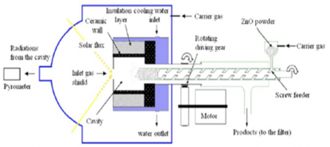
The maximum chemical conversion for reduction was 70%. After thirty cycles, there was no discernible degradation. The reactor was only able to reduce half of the material in it. Particle mixing was improved, gas stream loss was avoided, temperature measurements were more precise and the behavior of particles during nighttime was studied by authors. The rotary kiln in DLR's solar furnace is depicted in Figure 22. (22 kW). The DLR solar furnace's rotary kiln is depicted in Figure 22 (22 kW). In 1999, Haueter et al. [51] developed a 10 kW solar rotary reactor for thermally reducing ZnO to Zn and O2. Figure 23 depicts the ROCA prototype. Reactor concepts were sought out that respected the reaction's chemistry and used materials with a low thermal capacitance that could withstand temperature shocks. Its main component was an inconel steel rotating conical cavity-receiver with a small aperture for allowing concentrated solar radiation to enter. A concentric conical shell encased the water-cooled window. To keep the ZnO reactants flowing continuously, a screw powder feeder at the reactor's back fed them axially into the rotating cavity. As the centripetal acceleration pushed the ZnO powder into the wall, it created insulation and a thermal load reduction layer of ZnO. The continuous flow of inert gases entered and exited the cavity-receiver tangentially at the front, where they were swept out by a quenching device. Particles and condensable gases were kept out of the window by the purge, which also kept it cool and clear. The ZnO can be used with this arrangement.
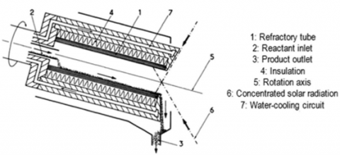
Figure 20. The rotary kiln developed by Flamant et al. [31]
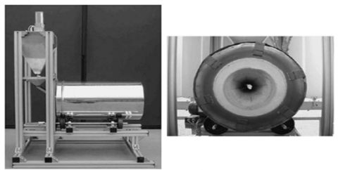
Figure 21. It shows images of the rotating kiln used to calcine calcite to produce lime [49]
Figure 22. Picture of DLR solar furnace rotary kiln [50]
Figure 23. Reduce ZnO in PSI with rotary reactors according to ref. [51, 52]
Served as an absorber of radiant energy, an insulator of heat, and a chemical reactant all at once. Temperatures nearing 2000 degrees Celsius were found to be possible with a uniform distribution throughout the reactor cavity. Low thermal inertia and high resistance to thermal shock made it a good choice for a heat exchanger. ZIRRUS, a novel reactor of equal power to ROCA, was proposed to correct some of ROCA's design and operational flaws according to suggestions Müller [52] and Abanades et al. [53]. The reactant ZnO was forced to fill the rotating cavity by centripetal acceleration. When compared to ROCA, where ZnO was used as both a catalyst and an insulator, ZIRRUS decoupled these roles. This means that for ZIRRUS to function in a corrosive environment containing ZnO, gaseous Zn, and O2 at the decomposition temperature of ZnO, it needed an inner cavity wall that was impervious to gas diffusion. Using a feeder that extends into and contracts from the cavity, a layer of ZnO was applied to this surface. Insulation that can withstand high temperatures was mainly stuffed behind the cavity. Through the reactor's window, an inert gas was blown, carrying the reaction products to the quench device. In ZIRRUS, on the other hand, the inert gas is heated to a temperature above Zn condensation before entering the cavity. A gas-tight cavity of HfO2 was used to prevent the diffusion of oxygen through ROCA's walls. Between the cold feeder and the water-cooled rotating cylinder wall, the product gas flowed. The cold wall and the injection of cold Ar help to promote the quench of Zn to Zn. " The results of the tests carried out at the PSI solar furnace were positive. Using ZnO as a conversion medium, ROCA only manages a 35% conversion rate. A temperature of 1900 K was recorded in the caverns. A significant improvement over ROCA's 20 percent recovery rate was achieved in each experiment, where only about 80 percent of the products could be recovered Verified by P. Haueter et al. [51]. It was later found that ZnO could be dissolved and reduced successfully. In addition, the reactor was tested at Odeillo's 1-MW Solar Furnace at a scale of 100 kW according to Alonso et al. [28]. Mechanical and thermal resistance were demonstrated for the large-scale prototype by Kogan rt al. [27] and Schunk et al. [54]. In Figure 23, ZIRRUS is depicted as a rotating cylindrical reactor developed by Abanades et al. [53] to reduce metallic oxides in the laboratory. It is a 30 mm diameter water-cooled rotating cavity with an aperture and hemispherical glass window surrounding it that receives the solar radiation and the material to be reduced in Figure 24. An insulation layer surrounds the ceramic cylinder (e.g. zirconia) inside the cell. Thermal equilibrium is reached in the insulated cavity first. After that, a screw feeder at the reactor's back continuously feeds the cavity with the reactant particles. Solid particles are heated primarily by solar and infrared light emitted by the cavity's hot walls. Studies on the materials' quality and ZnO reduction tests were carried out. With a high purity of zinc, the reactor was able to respond to concentrated solar flux reasonably. Eighty-seven percent (72%) of the dissociation yield has been reported. The radiation power and flux used for testing, as well as the quality of the design, determine the temperature the cavity can reach and ultimately whether mechanical or operational issues arise. Developing a solar reactor that works best often necessitates several previous attempts. Using the previously acquired information, complex prototypes are currently being developed. There are typically design or operational problems with early solar reactor prototypes that have been corrected in the design of current systems. Problems with material resistance and tiny chemical conversion are most often caused by an inadequate or wrong utilization of radiation power (and thus, the required temperature is not achieved). Growing larger is made easier by the information that has been gathered over time. Smaller reactors should be used to solve as many of the problems as feasible while developing a bigger, more complicated, and more expensive prototype. Among the reactors studied, Table 2 provides a summary of the most essential characteristics. Alternatively, the authors may not have included any information on a parameter that doesn't exist. The ratio of the reaction's process heat to the solar power input is what's known as the global efficiency of a chemical reaction. Consider the fact that the claimed chemical efficiency in every case is substantially dependent on the process length. If the reaction chamber's residence time for reactants is increased, a larger yield can be expected.
Figure 24. Rotating cylindrical reactor who designed it Abanades et al. [54]
Table 2. Summarizes the most important characteristics of the reactors studied in this study
|
Name of the solar reactor |
Type |
Reaction of chemicals |
Tried and tested in |
Solar-to-chemical conversion efficiency at its highest (%) point |
Max. measured temperature (K) |
Max chemical efficiency (%) |
Power range (kW) |
Author |
|
- |
Cyclonic |
Decomposition of calcite |
PSI solar heater |
43 |
1300 |
- |
- |
[18] |
|
SynMet |
Cyclonic |
In this process, ZnO and CH4 are converted into syngas and Zn |
Thermostat PSI |
- |
1600 |
90 |
5 |
[19, 20, 33,34] |
|
SynPet5 |
Cyclonic |
Petcoke steam gasification |
Thermostat PSI |
- |
1800 |
87 |
5 |
[19, 20, 33, 34] |
|
- |
Cyclonic |
Methane thermal splitting |
The solar furnace at the Weizmann Institute |
- |
1320 |
28.1 |
- |
[27] |
|
- |
Fluidized |
Decomposition of calcite |
Small solar heaters Odeillo |
14 |
1573 |
- |
2 |
[31] |
|
- |
Fluidized |
ZnO and CH4 are used to produce syngas and Zn. |
Sun-heated PSI |
- |
1373 |
43 |
- |
[19, 20, 33, 34] |
|
- |
Fluidized |
To capture atmospheric CO2, CaO carbonation/CaCO3 calcination is used |
Solar Simulator PSI |
- |
1150 |
- |
- |
[19, 20, 33, 34] |
|
- |
Fluidized |
Thermochemical cycle/gasification of NiFe2O2/M-ZrO2 WS |
Solar simulator at Niigata University |
- |
1473 |
45 |
2 |
[35, 36, 55] |
|
TREMPER |
Fixed |
reduction of MnO2, Fe2O3, and Fe3O4 |
PSI solar heater |
- |
2080 |
80 |
- |
[37, 28] |
|
- |
Fixed |
reduction of Mn3O4 |
Solar simulator by IMDEA Energy |
- |
1673 |
60 |
1 |
[28] |
|
- |
Fixed |
Reduction of Mn2O3, Mn3O4, and CeO2 |
Solar simulator by IMDEA Energy |
47 |
1723 |
10 |
2 |
[28] |
|
- |
Fixed |
ZnO removal |
PSI solar heater |
- |
2100 |
- |
- |
[38] |
|
- |
Fixed |
Reduction of CeO2 |
Solar furnace developed by CNRS-PROMES |
- |
2373 |
- |
2 |
[40, 41, 53] |
|
- |
Fixed |
A thermochemical cycle of H2O–CO2 based on CeO2. |
Solar Simulator PSI |
- |
1913 |
2 |
2 |
[12] |
|
- |
Fixed |
Reduction of ZnO and SnO2 |
Solar furnace developed by CNRS-PROMES |
- |
1900 |
2 |
1 |
[40, 41, 53] |
|
- |
Fixed |
Reduction of CeO2 and ferrites |
Tokyo Institute of Technology's Solar Simulator |
- |
1623 |
- |
- |
[42, 43] |
|
CR5 |
Fixed |
The thermochemical cycle of ferrites |
Solar furnace SNL |
20 |
1697 |
- |
9 |
[44] |
|
- |
Fixed |
Carbonaceous material gasification |
The US Army's White Sands Solar Facility |
- |
- |
19 - 48 |
10 |
[45] |
|
GRAFSTRR |
Mobile |
ZnO removal |
PSI solar simulator with high flux |
- |
1900 |
- |
10 |
[46, 47] |
|
- |
Rotary |
Decomposition of calcite |
Small solar heaters Odeillo |
30 |
1773 |
- |
2 |
[30] |
|
- |
Rotary |
Production of lime from limestone breakdown |
Sun-heated PSI |
20 |
1423 |
- |
10 |
[29, 49] |
|
- |
Rotary |
Cobalt oxide-based thermochemical energy storage |
Heater from the DLR solar power plant |
- |
1173 |
70 (reduction) |
- |
[50] |
|
ROCA |
Rotary
|
Reduced ZnO content |
Sun-heated PSI |
- |
2000 |
35 |
10 |
[51] |
|
ZIRRUS |
Rotary |
ZnO removal |
PSI solar heater |
- |
1900 |
90 |
10 |
[52] |
|
- |
Rotary |
ZnO removal |
- |
- |
1273 |
87 |
2 |
[40, 41, 53] |
As a result of an investigation into reactor design and improvement based on reaction chemistry, prevalent transport methods, and material compatibility, this work has been published. To date, solar thermal decomposition experiments have relied on solar simulators for around 81% of the total systems investigated and tested, with the reactors employed direct systems accounting for the majority of this research in terms of both solid-gas reactions and pyrolysis processes. Closed formation systems are required at high temperatures to increase the reactor's efficiency in using solar energy and to use fixed beds to undergo both processes and demonstrate better chemical conversion during thermal decomposition. Because a fluidized bed is known to outperform the two phases of gas and solid contact, and hence heat and mass transfer, it is preferable to employ a fluidized bed in solid-gas processes. For chemical processes involving solid gases, fluidized bed reactors, fixed bed reactors, and rotating reactors are the most prevalent. Researchers in solar chemistry have produced reactants that directly absorb radiation as a result of early investigations on particle futures and gas-solid solar reactors. More than 20 different solar reactor particles were tested experimentally for efficiency, maximum temperature, and mechanical or operational issues, and the type of reactor required, according to a summary, is the construction of an improved solar reactor from several previous attempts.
[1] Al Sahlani, A., Randhir, K., Ozalp, N., Klausner, J. (2021). A simplified numerical approach to characterize the thermal response of a moving bed solar reactor. Proc. ASME 2021 Heat Transf. Summer Conf. HT 2021, pp. 1-7. https://doi.org/10.1115/HT2021-63924
[2] Lattanzi, A., Hrenya, C. (2016). Final technical report: using solid particles as heat transfer fluid for use in Concentrating Solar Power (CSP) plants. https://www.osti.gov/servlets/purl/1253079%0Ahttp://www.osti.gov/servlets/purl/1253079/.
[3] Roy, C., Klausner, J.F., Bénard, A. (2021). Numerical study on the impact of fluid distribution on a counter-current direct contact evaporator. Int. J. Heat Mass Transf., 166: 120561. https://doi.org/10.1016/j.ijheatmasstransfer.2020.120561
[4] Morris, A.B., Pannala, S., Ma, Z., Hrenya, C.M. (2015). A conductive heat transfer model for particle flows over immersed surfaces. Int. J. Heat Mass Transf., 89: 1277-1289. https://doi.org/10.1016/j.ijheatmasstransfer.2015.06.004
[5] Auerkari, P. (1996). Mechanical and physical properties of engineering alumina ceramics. VTT Tied. - Valt. Tek. Tutkimusk., no. 1792.
[6] Almendros-Ibáñez, J.A., Soria-Verdugo, A., Ruiz-Rivas, U., Santana, D. (2011). Solid conduction effects and design criteria in moving bed heat exchangers. Appl. Therm. Eng., 31(6-7): 1200-1207. https://doi.org/10.1016/j.applthermaleng.2010.12.021
[7] Hamidi, M., Wheeler, V.M., Kreider, P., Catchpole, K., Weimer, A.W. (2019). Effective thermal conductivity of a bed packed with granular iron – manganese oxide for thermochemical energy storage. Chem. Eng. Sci., 207: 490-494. https://doi.org/10.1016/j.ces.2019.06.035
[8] Tuttle, J.F., White, N., Mohammadi, K., Powell, K. (2020). A novel dynamic simulation methodology for high temperature packed-bed thermal energy storage with experimental validation. Sustain. Energy Technol. Assessments, 42: 100888. https://doi.org/10.1016/j.seta.2020.100888
[9] Al-shankiti, I.A., Ehrhart, B.D., Ward, B.J., Bayon, A., Wallace, M.A., Bader, R., Kreider, P., Weimer, A.W. (2019). Particle design and oxidation kinetics of iron-manganese oxide redox materials for thermochemical energy storage. Sol. Energy, 183: 17-29. https://doi.org/10.1016/j.solener.2019.02.071
[10] André, L., Abanades, S., Flamant, G. (2016). Screening of thermochemical systems based on solid-gas reversible reactions for high temperature solar thermal energy storage. Renew. Sustain. Energy Rev., 64: 703-715. https://doi.org/10.1016/j.rser.2016.06.043
[11] Farcot, L., Le, N., Fourmigué, J. (2019). Experimental investigation of a moving-bed heat storage thermochemical reactor with SrBr2 / H2O couple. J. Energy Storage, 26: 101009. https://doi.org/10.1016/j.est.2019.101009
[12] Chueh, W.C., Falter, C., Abbott, M., Scipio, D., Furler, P., Haile, S.M., Steinfeld, A. (2010). High-flux solar-driven thermochemical dissociation of CO2 and H2O using nonstoichiometric ceria. Science, 330(6012): 1797-1801. https://doi.org/10.1126/science.1197834
[13] Furler, P., Scheffe, J., Gorbar, M., Moes, L., Vogt, U., Steinfeld, A. (2012). Solar thermochemical CO2 splitting utilizing a reticulated porous ceria redox system. Energy and Fuels, 26(11): 7051-7059. https://doi.org/10.1021/ef3013757
[14] Furler, P., Scheffe, J.R., Steinfeld, A. (2012). Syngas Production by a simultaneous splitting of H2O and CO2 via ceria redox reactions in a high-temperature solar reactor. Energy Environ. Sci., 5(3): 6098-6103. https://doi.org/10.1039/c1ee02620h
[15] Lede, J., Verzaro, F., Villermaux, J. (1980). Le cyclone: un nouveau réacteur chimique solaire gaz-solide Application à la mise en oeuvre en continu de la pyrolyse flash de sciure de bois. Rev. Phys. Appliquée, 15(3): 535-543. https://doi.org/10.1051/rphysap:01980001503053500
[16] Steinfeld, A. (2005). Solar thermochemical production of hydrogen - A review. Sol. Energy, 78(5): 603-615. https://doi.org/10.1016/j.solener.2003.12.012
[17] Puig-Arnavat, M., Tora, E.A., Bruno, J.C., Coronas, A. (2013). State of the art on reactor designs for solar gasification of carbonaceous feedstock. Sol. Energy, 97: 67-84. https://doi.org/10.1016/j.solener.2013.08.001
[18] Granqvist, C.G. (1991). The cyclone reactor- an atmospheric open solar reactor. Appl. Phys. A Solids Surfaces, 52(2): 83-93. https://doi.org/10.1007/BF00323721
[19] Steinfeld, A., Imhof, A., Mischler, D. (1992). Experimental investigation of an atmospheric-open cyclone solar reactor for solid-gas thermochemical reactions. J. Sol. Energy Eng., 114(3): 171-174. https://doi.org/10.1115/1.2930001
[20] Steinfeld, A., Brack, M., Meier, A., Weidenkaff, A., Wuillemin, D. (1998). A solar chemical reactor for co-production of zinc and synthesis gas. Energy, 23(10): 803-814. https://doi.org/10.1016/S0360-5442(98)00026-7
[21] Nikulshina, V., Hirsch, D., Mazzotti, M., Steinfeld, A. (2006). CO2 capture from air and co-production of H2 via the Ca(OH)2-CaCO3 cycle using concentrated solar power-Thermodynamic analysis. Energy, 31(12): 1715-1725. https://doi.org/10.1016/j.energy.2005.09.014
[22] Z’Graggen, A. (2008). Solar gasification of carbonaceous materials — reactor design, modeling and experimentation. ETH Zurich, 17741: 1-4.
[23] Z’Graggen, A., Haueter, P., Trommer, D., Romero, M., de Jesus, J.C., Steinfeld, A. (2006). Hydrogen production by steam-gasification of petroleum coke using concentrated solar power-II Reactor design, testing, and modeling. Int. J. Hydrogen Energy, 31(6): 797-811. https://doi.org/10.1016/j.ijhydene.2005.06.011
[24] Richter, C., Blanco, J., Heller, P., Mehos, M., Meier, A., Meyer, R. (2009). Solar power and chemical energy systems annual report. Int. Energy Agency.
[25] Z’Graggen, A., Steinfeld, A. (2008). Hydrogen production by steam-gasification of carbonaceous materials using concentrated solar energy - V. Reactor modeling, optimization, and scale-up. Int. J. Hydrogen Energy, 33(20): 5484-5492. https://doi.org/10.1016/j.ijhydene.2008.07.047
[26] Kogan, M., Kogan, A. (2003). Production of hydrogen and carbon by solar thermal methane splitting. I. The unseeded reactor. Int. J. Hydrogen Energy, 28(11): 1187-1198. https://doi.org/10.1016/S0360-3199(02)00282-3
[27] Kogan, A., Kogan, M., Barak, S. (2004). Production of hydrogen and carbon by solar thermal methane splitting. II. Room temperature simulation tests of a seeded solar reactor. Int. J. Hydrogen Energy, 29(12): 1227-1236. https://doi.org/10.1016/j.ijhydene.2003.12.002
[28] Alonso, E., Romero, M. (2015). Review of an experimental investigation on directly irradiated particles solar reactors. Renew. Sustain. Energy Rev., 41: 53-67. https://doi.org/10.1016/j.rser.2014.08.027
[29] Meier, A., Ganz, J., Steinfeld, A. (1996). Modeling of a novel high-temperature solar chemical reactor. Chem. Eng. Sci., 51(11): 3181-3186. https://doi.org/10.1016/0009-2509(96)00217-5
[30] Flamant, G., Thermochimie, G.F. (1980). Thermochimie solaire à hautes températures , résultats expérimentaux. Quelques perspectives d’application. Revue de Physique Appliquée, 15(3). https://doi.org/10.1051/rphysap:01980001503050300
[31] Flamant, G., Gauthier, D., Boudhari, C., Flitris, Y. (1988). A 50 kW fluidized bed high-temperature solar receiver: Heat transfer analysis. J. Sol. Energy Eng. Trans. ASME, 110(4): 313-320. https://doi.org/10.1115/1.3268273
[32] Sabatier, P. “I fé :%,” [Online]. Available: Université Paul Sabatier%0AUnité d’fcnsaignement et de Recherche de Physique • Chimie • Automatique.
[33] Steinfeld, A., Frei, A., Kuhn, P., Wuillemin, D. (1995). Solar thermal production of zinc and syngas via combined ZnO-reduction and CH4-reforming processes. Int. J. Hydrogen Energy, 20(10): 793-804. https://doi.org/10.1016/0360-3199(95)00016-7
[34] Nikulshina, V., Gebald, C., Steinfeld, A. (2009). CO2 capture from atmospheric air via consecutive CaO-carbonation and CaCO3-calcination cycles in a fluidized-bed solar reactor. Chem. Eng. J., 146(2): 244-248. https://doi.org/10.1016/j.cej.2008.06.005
[35] Gokon, N., Takahashi, S., Yamamoto, H., Kodama, T. (2008). Thermochemical two-step water-splitting reactor with internally circulating fluidized bed for thermal reduction of ferrite particles. Int. J. Hydrogen Energy, 33(9): 2189-2199. https://doi.org/10.1016/j.ijhydene.2008.02.044
[36] Gokon, N., Mataga, T., Kondo, N., Kodama, T. (2011). Thermochemical two-step water splitting by internally circulating fluidized bed of NiFe2O4 particles: Successive reaction of thermal-reduction and water-decomposition steps. Int. J. Hydrogen Energy, 36(8): 4757-4767. https://doi.org/10.1016/j.ijhydene.2011.01.076
[37] Frey, T., Guesdon, C., Sturzenegger, M. (2005). Kinetics on a second scale at temperatures up to 2300 K - The reduction of manganese oxide in a solar furnace. J. Am. Ceram. Soc., 88(11): 3249-3252. https://doi.org/10.1111/j.1551-2916.2005.00570.x
[38] Möller, S., Palumbo, R. (2001). Solar thermal decomposition kinetics of ZnO in the temperature range 1950-2400 K. Chem. Eng. Sci., 56(15): 4505-4515. https://doi.org/10.1016/S0009-2509(01)00113-0
[39] Keunecke, M., Meier, A., Palumbo, R. (2004). Solar thermal decomposition of zinc oxide: An initial investigation of the recombination reaction in the temperature range 1100-1250 K. Chem. Eng. Sci., 59(13): 2695-2704. https://doi.org/10.1016/j.ces.2004.03.019
[40] Abanades, S., Flamant, G. (2006). Thermochemical hydrogen production from a two-step solar-driven water-splitting cycle based on cerium oxides. Sol. Energy, 80(12): 1611-1623. https://doi.org/10.1016/j.solener.2005.12.005
[41] Chambon, M., Abanades, S., Flamant, G. (2012). Thermal dissociation of compressed ZnO and SnO2 powders in a moving-front solar thermochemical reactor. AIChE J., 59(4): 215-228. https://doi.org/10.1002/aic.12432
[42] Kaneko, H., Fuse, A., Miura, T., Ishihara, H., Tamaura, Y. (2006). Two-step water splitting with concentrated solar heat using the rotary-type solar furnace. In: Proceedings of the 12th SolarPACES Conference, Sevilla, Spain.
[43] Kaneko, H., Lee, C., Ishihara, T., Ishikawa, Y., Hosogoe, K., Tamaura, Y. (2009). Solar H2 production with tokyo tech rotary-type solar reactor to be tested using solar concentration system at csiro in Australia. Conference: ASME 2009 3rd International Conference on Energy Sustainability Collocated with the Heat Transfer and InterPACK09 Conferences, pp. 1-6. https://doi.org/10.1115/ES2009-90420
[44] Hogan, R.E., Siegel, N.P., Hogan, R.E., Allendorf, M.D., Stuecker, J.N., James, D.L. (2008). Innovative solar thermochemical water splitting. Technical Report. https://doi.org/10.2172/932876
[45] Gregg, D.W., Taylor, R.W., Campbell, J.H., Taylor, J.R., Cotton, A. (1980). Solar Gasification of coal, activated carbon, coke and coal and biomass mixtures. Sol. Energy, 25(4): 353-364. https://doi.org/10.1016/0038-092X(80)90347-3
[46] Koepf, E., Advani, S.G., Steinfeld, A., Prasad, A.K. (2012). A novel beam-down, gravity-fed, solar thermochemical receiver/reactor for direct solid particle decomposition: Design, modeling, and experimentation. Int. J. Hydrogen Energy, 37(22): 16871-16887. https://doi.org/10.1016/j.ijhydene.2012.08.086
[47] Koepf, E., Advani, S.G., Prasad, A.K. (2011). Design of a novel high-temperature gravity-fed solar thermochemical reactor for solar-fuels production: Case study - ZnO powder. ASME 2011 5th International Conference on Energy Sustainability, https://doi.org/10.1115/ES2011-54204
[48] Sammouda, H., Royere, C., Belghith, A., Maalej, M. (1999). Heat transfer in a rotating furnace of solar sand! the boiler at a 0999 kW thermal concentration system. Renew. Energy, 17(1): 21-47. https://doi.org/10.1016/S0960-1481(98)00037-8
[49] Meier, A., Bonaldi, E., Cella, G. M., Lipinski, W., Wuillemin, D., Palumbo, R. (2004). Design and experimental investigation of a horizontal rotary reactor for the solar thermal production of lime. Energy, 29(5-6): 811-821. https://doi.org/10.1016/S0360-5442(03)00187-7
[50] Neises, M., Tescari, S., de Oliveira, L., Roeb, M., Sattler, C., Wong, B. (2012). Solar-heated rotary kiln for thermochemical energy storage. Sol. Energy, 86(10): 3040-3048. https://doi.org/10.1016/j.solener.2012.07.012
[51] Haueter, P., Moeller, S., Palumbo, R., Steinfeld, A. (1999). The production of zinc by thermal dissociation of zinc oxide - Solar chemical reactor design. Sol. Energy, 67(1-3): 161-167. https://doi.org/10.1016/s0038-092x(00)00037-2
[52] Müller, R., Haeberling, P., Palumbo, R.D. (2006). Further advances toward the development of a direct heating solar thermal chemical reactor for the thermal dissociation of ZnO(s). Sol. Energy, 80(5): 500-511. https://doi.org/10.1016/j.solener.2005.04.015
[53] Abanades, S., Charvin, P., Flamant, G. (2007). Design and simulation of a solar chemical reactor for the thermal reduction of metal oxides: A case study of zinc oxide dissociation. Chem. Eng. Sci., 62(22): 6323-6333. https://doi.org/10.1016/j.ces.2007.07.042
[54] Schunk, L.O., Haeberling, P., Wept, S., Wuillemin, D., Meier, A., Steinfeld, A. (2008). Receiver-reactor for the solar thermal dissociation of zinc oxide. J. Sol. Energy Eng. Trans. ASME, 130(2): 0210091-0210096. https://doi.org/10.1115/1.2840576
[55] Gokon, N., Ichi Inuta, S., Yamashita, S., Hatamachi, T., Kodama, T. (2009). Double-walled reformer tubes using high-temperature thermal storage of molten salt/MgO composite for solar cavity-type reformer. Int. J. Hydrogen Energy, 34(17): 7143-7154. https://doi.org/10.1016/j.ijhydene.2009.06.047