Zainab Al-Ammar* | Karima Esmail Amori
© 2022 IIETA. This article is published by IIETA and is licensed under the CC BY 4.0 license (http://creativecommons.org/licenses/by/4.0/).
OPEN ACCESS
The separation of fluid-fluid mixtures is a major issue in various sectors. The liquid-liquid hydro-cyclone has a wide range of applications in various sectors due to its great efficiency in separating fluid mixtures, ease of installation, and low cost. In crude oil production, high water is consumed following the degrading of production quality, high processing costs, costs, and environmental impacts. Axial hydro cyclone is a tool for Downhole Oil/Water Separation (DOWS) in the petroleum production industry, but it has limitations. The main purpose of this work is to simulate the effect of compacting the conventional inline hydro cyclone with a converging-diverging nozzle on the oil/water dynamic flow and the separation process to resolve the high water cut problem. This study presents a three-dimensional simulation to compute fluid dynamics using the mixture multiphase and SST k-omega turbulence models for Reynolds numbers less than 66000. The operational flow variables are a mixture: flow rate (14, 28, and 56 m3/h) and oil/water ratio (15/85, 25/75, 30/70, and 35/65). Results indicate an enhancement in the axial and tangential velocity components by 15% and 50%, respectively, for the proposed design compared with the conventional cyclone. The oil separation efficiency for the new design is 89%, while for the conventional cyclone is 60%.
CFD, axial hydro cyclone, two phase, oil/water flow, turbulence model, DOWS
The water content of output fluids is constantly growing due to large-scale exploitation of deep-sea petroleum resources, to the point where most water treatment facilities have surpassed their max capacity [1]. To address this issue, the downhole oil-water separation (DOWS) method was suggested that entails installing hydro cyclones downhole to pre-separate oil and water before pumping the oil to the surface and re-injecting the water back into the well [2, 3]. The hydro cyclone-based Downhole Oil/Water Separating System (DOWS) is the fundamental technology for producing treated water and cleaning up oil spills. Hydro cyclones are high-swirl flow device that uses centrifugal force to separate fluids with different densities. Axial intake hydro cyclones have a cylindrical inlet, stationary guide vans that create swirl flow, a pick-up tube, and annular water output. Hydro cyclones are devices that use the high centrifugal force created by spinning flow to separate two phases of differing densities [4]. The most prevalent liquid-liquid hydro cyclones are deoiling hydro cyclones utilized for oily wastewater in offshore sites [5]. However, various drawbacks have been discovered when using a typical deoiling hydro cyclone with a tangential intake for swirl formation [6, 7]. Due to the tangential hydro cyclone’s non-axisymmetric inlet [8], the vortex flow is easy to swing, causing oil droplet disintegration and high turbulent intensity, affecting separation efficiency [9]. Furthermore, the tangential inlet produces a high bulk and wastes much energy. Axial hydro cyclones have been designed to address the aforementioned flaws [10].
Axial hydro cyclones have lower levels of turbulence, a lower pressure drop, and a higher handling capacity than tangential hydro cyclones, making them more suitable for downhole oil-water extraction [11]. Shi and Xu [12] introduced the axial hydro cyclone for oil-water separation, where a guide vane was inserted in a straight pipe to create a swirling flow. According to the following research, the oil and water separation has been effectively performed in the powerful swirling flow field formed by the guide vane [13, 14]. Many axial hydro cyclones are introduced and investigated [15-17]. According to the findings, an axial hydro cyclone with a compact dimension, straight-through flow, and little pressure drop seems to be an excellent choice for DOWS use. Nevertheless, most investigations only provide qualitative data, and the stated axial hydro cyclone’s maximal capacity is 12 m3h-1. The handling capability must be expanded even further.
The first traditional liquid-liquid hydro cyclone separator (LLHC) design was produced by Dirkzwager [18] to study the flow behavior for single and two-phase flow in axial inlet cyclones. Delfos et al. [19] predicted a numerical model for liquid-liquid turbulent flow called (HAAS), and it showed that the HAAS model is very time efficient in the design cyclone [20] using the Euler-Euler approach for a higher volumetric ratio (over 10%) in the investigation a three-dimensional oil-water turbulent flow and oil separation process in a double-cone liquid-liquid hydro-cyclone (LLHC). Murphy et al. [21] investigated numerically and experimentally the two-phase flow through axial inlet hydro cyclone. Nascimento et al. [22] found that the swirl number at any location along the tube length depends on the swirl number at the inlet, Reynolds number, the distance from the tube inlet, the tube diameter, and the nature of the inlet swirl. Zhang et al. [23] showed the sensitivity of flow field and cyclone efficiency with the variation of the swirl vanes geometry experimentally. Rocha et al. [24] investigated numerically and experimentally one phase laminar flow in axial hydro cyclone to show the flow features and pressure drop under swirl flow conditions. Using the numerical approach, the literature survey showed that more details could be obtained about the feature of the swirl flow in a vane-type cyclone, and the effect of design parameters [25] show that for 45° and 72° fluid swirl angle. The recirculation zone was not predicted when using the conical outlet cyclone. Also, the droplet separation improvement [26] showed an increase in the blade deflection angle number of fans; the inlet flow rate would increase the swirl. That led to increased separation efficiency [27] investigated the flow field numerically inside axial hydro cyclone by using the RNG –kε model and discrete phase model (DPM), its show that the separation efficiency increases with increase the droplet diameter up 40 µm. The numerical analyses predicted the improvement in the separation with an increase in the van's number and a decrease in the outlet fluid angle. Rocha [28] show the effect of the oil droplet diameter on the flow behavior inside the cyclone. It shows that as oil particle diameter increases, the particle will be closer to the center. Also, as the Reynold number increases, the test tube length required for the flow to reach stability increases. Hamza et al. [29] studied the effect of replacing the cylindrical tube with the conical tube cyclone. This Causes a reduction in the recirculation zone and improves the separation efficiency by raising the tangential and axial velocity components, which is considered a worthwhile improvement in the cyclone specifications.
Nunes et al. [30] studied numerically the separation of oil/water mixture by filtering hydro-cyclone (a porous ceramic membrane) and compared it with the conventional cyclone. Eulerian–Eulerian approach and the turbulence model are applied in this study. The hydro cyclone's velocity, pressure drop, and separation performance were analyzed. The results showed that due to the effect of the porous wall, the oil phase was unstable in the cyclone core. The oil concentration and pressure are lower inside the filtering hydro cyclone than a conventional cyclone. Also, the separation efficiency by using porous walls is reduced by about 5%.
Zhan et al. [31] designed an axial inlet hydro cyclone with two stages of the separator and two light phase outlets. The effect of the flow rate, oil volume fraction, and the split ratio on the predicted cyclone was investigated for the water flow rate (4–7 m3/h) and oil fraction (1%–10%). The results show that the split ratio affected the separation efficiency. Also, the experimental results appeared that the predicted design is suitable for less than 10% oil fraction, and its structure required optimization to extend its application. Zhan et al. [32] studied the effect of the swirl structure parameters on the velocity field for single-phase flows numerically. The results show that the separator parameters (vane outlet and twist angles as well as the number of vanes) have a proportional effect on the swirling flow inside the hydro cyclone., The tangential velocity is improved, and then the separation process. Zeng et al. [33] investigated the flow behavior numerically inside axial flow hydro cyclone to present the structural cyclone effect on the pressure drop and velocity field using mixture multiphase and Reynolds stress turbulence models. Three different cyclone structures are used; each contains two swirl generators with two light phase outlets. The test chamber for the first cyclone is a conventional cylindrical tube, the second cyclone is a conical diffuser tube, and that for the last is multiple stages of contraction. Results showed that the third cyclone structure has a higher pressure drop than the second cyclone, and these two cyclones are more efficient than conventional cylindrical cyclone tubes.
The axial inlet hydro cyclone used in DOWS application is taken little attention in the previous study compared with other types of the hydro cyclone. The purpose of the current investigation is to improve the DOWS technology to enhance the hydrocarbon recovery of high water cut affected oil wells production and reduction the oil production cost. In this work, a new design of the axial inlet hydro cyclone is investigated numerically by using ANSYS fluent. The numerical results of the predicted design are discussed and compared with conventional design results in terms of cyclone efficiency, velocity component, and oil distribution.
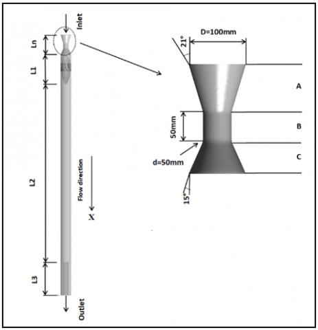
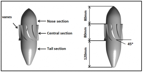
The axial inlet hydro cyclone used in this work is shown in Figure 1, with the detailed dimensions given in Table 1 created using solid work software. It mainly consists of a converging-diverging nozzle, guide vanes separator, cylindrical wall, central oil discharge tube, and annular water outlet. The converging-diverging nozzle geometry is based on classical venture tube BSI measurement [34]. The separator consists of 9 vanes which are placed within a tube. This separator, Figure 2, consists of a central body with dimensions 80mm diameter and 80 mm height equipped with vanes that deflect the flow. The upper part of the separator is denoted as a nose section. It is designed as a smooth and sharp tip to distribute the incoming fluid to the annular area without deformation. The bottom part is marked as a tail section. The vanes are attached to the tube wall to fix the separator. The oil-water mixture enters axially to the hydro cyclone, and a swirling flow is generated after passing through the separator. Dependent on the centrifugal force generated by the pressure gradient in swirling flow, the light phase droplets move inward and develop a continuous oil core in the switches tube; the light and heavy phase can be discharged from at the end of the test tube, respectively.
Table 1. Geometrical dimension of the conventional hydro cyclone
|
Ln (mm) |
L1 (mm) |
L2 (mm) |
L3 (mm) |
D (mm) |
Di (mm) |
|
208 |
280 |
1700 |
30 |
100 |
50 |
The flow behavior inside the cyclone is investigated by the fundamental principles of classical fluid mechanics expressing the conservation of mass and momentum. The continuity and momentum equations for turbulent, isothermal, incompressible flow are [35]:
$\frac{\partial}{\partial t}\left(\alpha_{q} \rho_{q}\right)+\nabla \cdot\left(\alpha_{q} \rho_{q} \vec{u}_{q}\right)=0$ (1)
Figure 1. The geometry of conventional hydrocyclone with convergent-divergent nozzle
Figure 2. Separator
$\rho_{q} \alpha_{q}\left(\frac{\partial \vec{u}_{q}}{\partial t}+\vec{u}_{q}\left(\vec{u}_{q} \cdot \nabla\right)\right)$
$=-\alpha_{q} \nabla P+\nabla \cdot\left(\alpha_{q} \sigma\right)+\alpha_{q} \rho_{q} g$
$+\rho_{q} \nabla \cdot\left(\alpha_{q}\left\langle\bar{u}_{q} \bar{u}_{q}\right\rangle\right)+R_{p q}$ (2)
where,
P is the pressure shared by all phases,
αq is the volume fraction of phase q,
$\vec{u}_{\mathrm{q}}$ is the mean velocity,
σ is the viscous stress tensor given by:
$\sigma=\mu_{\mathrm{q}}\left(\nabla \vec{u}_{\mathrm{q}}+\nabla \vec{u}_{\mathrm{q}}^{\mathrm{T}}\right)$
$\vec{u}_{\mathrm{q}}^{\mathrm{T}}$ is the turbulent velocity fluctuation.
Req is the interface force, this force depends on the friction, pressure, cohesion, and other effects, and is subjected to the conditions:
$\vec{R}_{\mathrm{pq}}=-\vec{R}_{\mathrm{qp}}$ (3)
$\vec{R}_{\mathrm{qq}}=0$ (4)
This force defined as:
$\sum_{p=1}^{n} \vec{R}_{\mathrm{pq}}=\sum_{p=1}^{n} K_{p q}\left(\vec{u}_{\mathrm{p}}-\vec{u}_{\mathrm{q}}\right)$ (5)
Kpq=(Kqp) is the interphase momentum exchange coefficient Eq. (6).
Momentum transfer between the phases is dependent on the value of the fluid-fluid exchange coefficient Kpq. For liquid-liquid mixture, the exchange coefficient Kpq is indicated how the secondary phase (droplet or bubble) do affect the predominant fluid. It can be defined as follows:
$K_{p q}=\frac{\alpha_{q} \alpha_{p} \rho_{p} f}{\tau_{p}}$ (6)
where,
f is the drag function.
τp, the particulate relaxation time and is defined as Eq. (7):
$\tau_{p}=\frac{\rho_{p} d_{p}^{2}}{18 \mu_{q}}$ (7)
dp is the diameter of the bubbles or droplets of phase p.
Nearly all definitions of (f) Eq. (8) include a drag coefficient (CD) that is based on the relative Reynolds number (Re) Eq. (9). For the model of [36]:
$f=\frac{C_{D} R e}{24}$ (8)
CD =0.44 for Re number up to 1000.
Here Re is the Reynolds number based on the relative velocity:
$R e=\frac{\rho_{q}\left|\vec{u}_{p}-\vec{u}_{q}\right| d_{p}}{\mu_{q}}$ (9)
The turbulence model (Shear Stress Transport) SST k-omega is used since it has a low computational cost and low iteration time compared to its sensitivity to the complex flow field inside the cyclone. The turbulence governing differential equations are [37, 38] (Eq. (10)):
$\rho \frac{\partial k}{\partial t}+U_{j} \rho \frac{\partial k}{\partial x_{j}}=\tau_{i j} \frac{\partial u_{i}}{\partial x_{j}}-\beta^{*} \rho \omega k+\frac{\partial}{\partial x_{j}}\left[\left(\mu+\sigma_{k} \mu_{t}\right) \frac{\partial k}{\partial x_{j}}\right]$ (10)
$\frac{\partial \omega}{\partial t}+\rho U_{j} \frac{\partial \omega}{\partial x_{j}}=\frac{\gamma}{v_{t}} \tau_{i j} \frac{\partial u_{i}}{\partial x_{j}}-\beta \rho \omega^{2}$
$+\frac{\partial}{\partial x_{j}}\left[\left(\mu+\sigma_{\omega} \mu_{t}\right) \frac{\partial \omega}{\partial x_{j}}\right]$
$+2 \rho\left(1-F_{1}\right) \sigma_{\omega_{2}} \frac{1}{\omega} \frac{\partial k}{\partial x_{j}} \frac{\partial \omega}{\partial x_{j}}$ (11)
The constants Φ of this model are calculated from the constants Φ1 and Φ2 as follows in Eq. (12):
$\Phi=F_{1} \Phi 1+\left(1-F_{1}\right) \Phi 2$ (12)
where,
F1 is blending Function and is defined:
$F_{1}=\tanh \left(\operatorname{ar} g_{1}^{4}\right)$ (13)
$\arg _{1}=\min \left[\max \left(\frac{\sqrt{k}}{0.09 \omega y}, \frac{500 v}{y^{2} \omega}\right), \frac{4 \rho \sigma_{\omega 2} k}{C D_{k \omega} y^{2}}\right]$
where, y is the distance to the next surface and CDkω is the positive portion of the cross-diffusion term:
$C D_{k \omega}=\max \left(2 \rho \sigma_{\omega 2} \frac{1}{\omega} \frac{\partial k}{\partial x_{j}} \frac{\partial \omega}{\partial x_{i}}, 10^{-10}\right)$ (14)
Kinematic eddy viscosity is defined as:
$v_{T}=\frac{a_{1} k}{\max \left(a_{1} \omega, \Omega F_{2}\right)}$ (15)
where, Ω is the absolute value of the vorticity and evaluated such that:
$\Omega=\sqrt{2 w_{i j} w_{i j}}$ (16)
$w_{i j}=\frac{1}{2}\left(\frac{\partial u_{i}}{\partial x_{j}}-\frac{\partial u_{j}}{\partial x_{i}}\right)$ (17)
F2 is the second blending function and is defined as:
$F_{2}=\tanh \left[\left[\max \left(\frac{2 \sqrt{k}}{\beta^{*} \omega y}, \frac{500 v}{y^{2} \omega}\right)\right]^{2}\right]$ (18)
The SST turbulence model constants are:
$\sigma_{\mathrm{k} 1}=0.85 ; \sigma_{\omega 1}=0.5 ; \beta_{1}=0.075 ; \mathrm{a}_{1}=0.31 ; \beta^{*}=0.09$;
$\mathrm{k}=0.41 ; \gamma_{1}=\frac{\beta_{1}}{\beta^{*}}-\sigma_{\omega 1} \mathrm{k}^{2} / \sqrt{\beta^{*}}$
$\sigma_{\mathrm{k} 2}=1 ; \sigma_{\omega 2}=0.856 ; \beta_{2}=0.0828$;
$\beta^{*}=0.09 ; \mathrm{k}=0.41 ;$ and $\gamma_{2}=\frac{\beta_{2}}{\beta^{*}}-\sigma_{\omega 2} \mathrm{k}^{2} / \sqrt{\beta^{*}}$
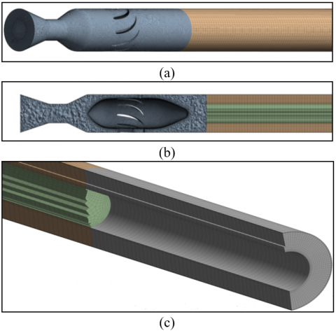
Because of the complex computational model, two types of mesh have been used in this work structural and unstructured mesh. The geometry mesh is divided into two regions. The top region consists of the converge-diverge nozzle and the separator section, meshing with the unstructured element. The bottom region consists of a cylindrical domain with a structural hexahedral element.
A computational mesh has been generated with 3.1 million elements; extra work and care were taken to have a good quality mesh of skewness of 0.18. Figure 3 shows the mesh on the surface and the plane through the axis of the separator. The mesh is refined near the wall on the separator, the surface to capture the flow behavior. SIMPLE-algorithm is used for pressure-velocity coupling; diffusive and advective terms were discretized using a hybrid scheme.
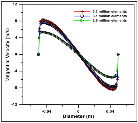
5.1 Grid independency
Grid independency is performed in which three different grids are used, coarser mesh 2.9 million elements, medium mesh 3.1 million elements, and fine mesh 3.3 million elements. The tangential velocity distribution at x= 0.5m after the separator is presented for these grid systems, as shown in Figure 4. It can be shown that the difference in the tangential velocity between the coarser and medium mesh is relatively large, whereas the difference between medium and fine mesh is less than 5%. Hence the medium system estimate is selected in this work.
Figure 3. Three dimensional mesh generation for hydrocyclone (a) Inlet zone, (b) Cross-sectional view, (c) Outlet zone
Figure 4. Tangential velocity distribution at different grid numbers of the same model at X = 0.5m
5.2 Boundary conditions
A two-phase flow occupies the computational domain. Water corresponds to the continuous phase, and the oil represents the dispersed phase within a droplet diameter D = 100 µm and volume fraction 0.25. The density and viscosity of water are 1067.8 kg/m3, 1.183x10⁻³ kg/ms, and that for oil is 869 kg/m3, 8.690x10⁻³ kg/ms, respectively. As a boundary condition, the inlet is defined as a uniform velocity inlet and is taken as 1m/s. The outlets are set to be outflow; all information of the numerical approach and boundary condition is shown in Table 2. No-slip boundary conditions are used at solid walls.
Table 2. Boundary conditions were used in the simulation
|
Input-output |
Information |
|
Time regime |
Steady |
|
Multiphase model |
Eulerian |
|
Drag coefficient |
Schiller Naumann |
|
Surface Tension (N/m) |
0.021 |
|
Turbulence model |
k-omega- SST |
|
Inlet |
Velocity inlet |
|
Outlet |
Outflow |
|
Pressure-velocity coupling algorithm |
SIMPLE |
|
Spatial discretization |
Second-order upwind |
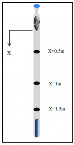
Oil/water mixture enters the hydro cyclone with an inlet axial velocity of 1 m/s, a flow rate of 28 m3/h, an oil volume fraction of 0.25, and a flow split of 0.3. Three horizontal planes were cut to analyze the flow behavior to investigate the swirling intensity after the fluid through the guide vanes at different locations, as shown in Figure 5.
Figure 5. Hydrocyclone view with three vertical heights
6.1 Axial velocity
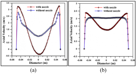
The numerical results for the axial velocity inside the hydro-cyclone are shown in Figures 6 and 7. The axial velocity reaches its peak value in the annular region, indicating the favorable forward positive velocity. Its value rapidly decreases toward the wall, where it falls to zero (no-slip condition). As proceeded to the tube core, its rate declined to the negative value, where the unfavorable backward velocity appeared. The increase in the favorable axial velocity after adding nozzle is shown in Figure 6 a and b. Figure 6a shows that with adding nozzle, the backflow velocity is increased due to the increase of the swirl intensity; on the other hand, the forward axial velocity for the new design is higher than a conventional cyclone, and this approve the cyclone work. This behavior extent along the test pipe as shown in Figure 6b.
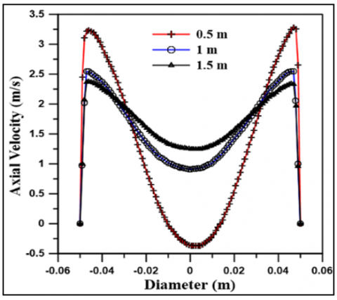
The axial velocity distribution for the nozzle-cyclone at the three plans is shown in Figure 7. The axial velocity distribution at x= 0.5m, x=1m, and x=1.5 m shows the backflow decrease as it proceeds to the tube exit, which is normal behavior due to a reduction in recirculation flow. These results consider a good agreement with the similar velocity profile observed by Shuja et al. [39].
Figure 6. Comparison of the axial velocity with and without nozzle at a) 0.5 m b)1.5 m
Figure 7. Axial velocity distribution along the test tube
6.2 Tangential velocity
Tangential velocity is the dominant component of the separator and the key factor that responds to the centrifugal force. It has a direct effect on separation deterioration and cyclone efficiency. The centrifugal force and separation efficiency will increase [40].
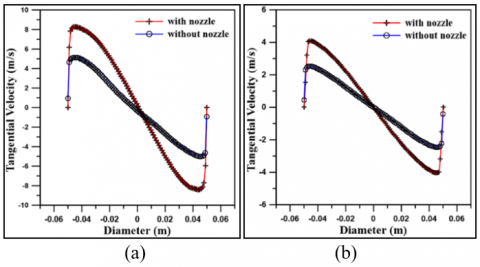
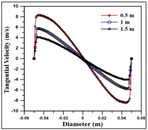
Figure 8 shows the tangential velocity distribution with and without nozzle at 0.5 and 1.5 m after the separator. The reported value shows that the development in tangential velocity reaches 50% when adding a nozzle. The maximum Van at any axial location with nozzle add is higher than the conventional cyclone. The increase in the tangential velocity leads to an increase in the swirling intensity, preserving the swirling from decay for a long distance after the separator. Figure 9 shows the decrease in the tangential velocity as we proceed toward the tube exit, this is attributed to the swirl decay caused by wall fraction, but adding the nozzle, Vtan still attains higher than a conventional cyclone.
Figure 10 shows the tangential velocity contour along the axial direction. The improvement appears on the tangential velocity, where its effect extended 75% from the test tube. While for conventional cyclones, this effect represents about 25% after the flow exit from the separator. Such a manner is favored since a larger centrifugal force can be imposed on the particle for better separation. Inserting a nozzle can increase tangential velocity for higher performance.
Figure 8. Comparison of the tangential velocity with and without nozzle at a) 0.5m, b) 1.5 m
Figure 9. Tangential velocity distribution along the tube
Figure 10. Tangential velocity contour with and without nozzle along the axial direction
6.3 Oil volume fraction
The distribution of the oil volume fraction is the major importance for the separation performance of the hydrocyclone. The oil volume fraction distribution for the two cases (with and without nozzle) has been simulated numerically for the inlet oil volume fraction 0.25, and flow split 0.3.
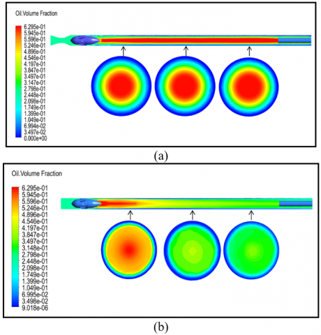
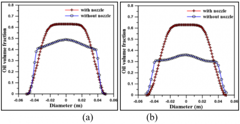
Oil moves away from the outer region of the tube towards the center; as soon as the mixture leave separator, a large region of oil-rich fluid is seen. As shown in Figure 11a, when adding a nozzle, the oil volume fraction fills 70% of the total volume of the test tube. The oil fraction value reached over 0.6; this attitude remains constant and stable along the test tube. For conventional cyclone, Figure 11b, the oil fraction reached the maximum amount immediately after the mixture leave separator where the flow is unstable. Reverse flow is maximum in this region so that this oil will be recirculated to the wall. Far from the separator, the oil volume fraction value inclined gradually and reached the constancy approximate at x= 0.25m after the separator, where its value was stable at 0.45. This enhancement results in the oil volume fraction when using the nozzle are clearly shown in Figure 12 at cross-section 0.5m and 1.5m after the separator.
Figure 11. Oil volume distribution along with the hydrocyclone (a) With nozzle (b) Without nozzle
Figure 12. Comparison of the oil volume fraction with and without nozzle at a) 0.5m, b) 1.5 m
Figure 13. Oil volume fraction distribution along the tube
Figure 14. Exit oil volume fraction for two cases with and without nozzle at αinlet=0.25, ṁ =28 m3/hr
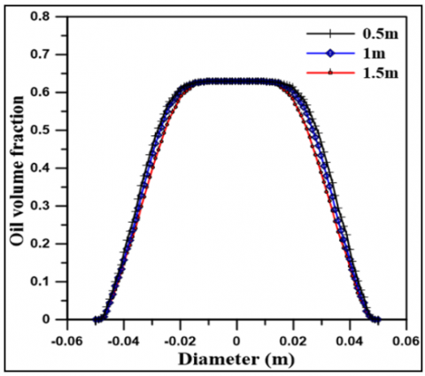
Figure 13 illustrates the oil volume fraction distribution at x=0.5m, 1m, and 1.5m. It shows that the oil core becomes narrower to the center as it reaches the light phase outlet this means the flow becomes stable at the quarter part of the tube.
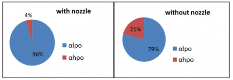
The oil volume fraction at the lpo and hpo for the same inlet oil volume fraction (0.25) is shown in Figure 14. Adding the convergent-divergent nozzle to the hydrocyclone is important in enhancing the ratio of oil to water in the lpo. It shows that the oil fraction exit with the water phase is radiuses 17% when using a convergent-divergent nozzle, indicating improvement in the separation process of the hydrocyclone.
6.4 Effect of inlet flow rate
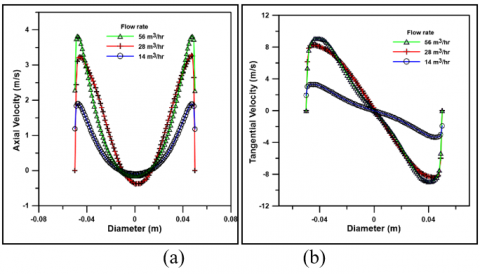
The effect of variation inlet flow rate was investigated with oil fraction 0.25, where it is considered the main parameter that affects the separation process. Figure 15a shows an improvement in the axial velocity as the flow rate increases. The influence of increasing the inlet flow rate on the swirling intensity increase and then tangential velocity is shown in Figure 15b. Also, it observed that the increase in the axial and tangential velocity is doubled when the inlet flow rate increased up 14 m3/hr, while this increase will be less affected at a flow rate up 28 m3/hr.
The effect of varying inlet flow rate on the separation efficiency for two cases (with and without nozzle) is shown in Figure 16, at αinlet=0.25 The separation efficiency increases as the flow rate increased from 14 m3/hr to 28 m3/hr, further, the flow rate did not improve. Excessive increase in the rotational fluid's flow rate inside the hydro-cyclone increases, making the breaking of the oil droplets into smaller ones and converting the oil/water mixture to the emulsion; this has negative effects on the performance of the hydro cyclone [24]. Also, the figure shows clear development figured in the Separation efficiency for the hydro cyclone with nozzle by comparison of a hydro cyclone without the nozzle.
Figure 15. Velocity components distribution at x=0.5m for different flow rate (a) Tangential, (b) Axial
Figure 16. Separation efficiency for three different inlet flow rates for two cases with and without nozzle
6.5 Effect of inlet oil volume fraction (αinlet)
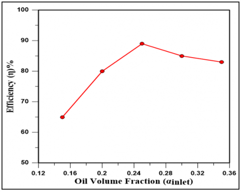
Figure 17. Effect of variation inlet oil volume fraction (αinlet) on cyclone efficiency at flow rate 28 m3/hr
Figure 17, present the separation efficiency for different oil volume fraction (0.15, 0.25, 0.3, 0.35) at flow rate 28m3/hr. It has been observed that the separation efficiency increase as αinlet increases from 0.15 to 0.25, where it reaches a maximum level (89%). As the oil volume fraction increased, the separation efficiency observed decreased, which indicated that with the increase of the mixture viscosity and shear resistance, the centrifugal force becomes weak, negatively affecting the hydro cyclone's separation process.
Per the obtained numerical results, the conclusions drawn are:
The following suggestions are recommended for future work:
|
Latin symbol |
|
|
CD |
Drag coefficient |
|
CDkω |
Positive portion of the cross-diffusion term: |
|
D |
Cyclone diameter (mm) |
|
Di |
Pickup tube diameter (mm) |
|
d |
Nozzle throat diameter (mm) |
|
dp |
Oil drop diameter(µm) |
|
f |
Drag function |
|
F1 |
Blending Function |
|
F2 |
Second blending function |
|
g |
Gravitational acceleration (m/s2) |
|
k |
Turbulence Kinetic Energy |
|
Kpq |
Interphase momentum exchange coefficient |
|
Ln |
Axial nozzle length (mm) |
|
L1 |
Axial separator length (mm) |
|
L2 |
Cyclone test tube length (mm) |
|
L3 |
Pickup tube length (mm) |
|
$\dot{m}$ |
Flow rate (m3/hr) |
|
Rpq |
Interface force |
|
Re |
Reynolds' number |
|
$U_{j}$ |
velocity component (m/s) |
|
$\vec{u}$ |
Mean velocity (m/s) |
|
$\nabla \vec{u}$ |
Turbulent velocity fluctuation (m/s) |
|
X |
Axial direction |
|
$x_{j}$ |
Coordinate (m) |
|
y |
Distance to the next surface |
|
Greek symbols |
|
|
α |
Volume fraction, or Turbulence model constants |
|
β |
Turbulence model constants |
|
µ |
Dynamic viscosity(kg/ms) |
|
μt |
Turbulent eddy viscosity(kg/ms) |
|
ν |
Kinematic viscosity(m2/s) |
|
ω |
Specific dissipation rate |
|
Ω |
The absolute value of the vorticity |
|
$\rho_{j}$ |
Density (kg/m3) |
|
σ |
Turbulence model constants, or viscous stress tensor (kg/ms2) |
|
Abbreviations |
|
|
CFD |
Computational Fluid Dynamics |
|
DOWS |
Downhole Oil/Water Separation |
|
LLHC |
Liquid-Liquid Hydrocyclone |
|
lPO |
light phase outlet |
|
hPO |
heavy phase outlet |
|
SST |
Shear Stress Transport |
[1] Belaidi, A., Thew, M.T., Munaweera, S.J. (2003). Hydrocyclone performance with complex oil‐water emulsions in the feed. The Canadian Journal of Chemical Engineering, 81(6): 1159-1170. https://doi.org/10.1002/cjce.5450810605
[2] Amini, S., Mowla, D., Golkar, M., Esmaeilzadeh, F. (2012). Mathematical modelling of a hydrocyclone for the down-hole oil–water separation (DOWS). Chemical Engineering Research and Design, 90(12): 2186-2195. https://doi.org/10.1016/j.cherd.2012.05.007
[3] Vieira, L.G.M. (2006). Optimization of separation processes in filtering hydrocyclones. Ph.D. Thesis, Federal, University of Uberlândia, Uberlândia, Brazil.
[4] Slot, J.J., van Campen, L.J.A.M., Hoeijmakers, H.W.M., Mudde, R.F. (2011). In-line oil-water separation in swirling flow. 8th International Conference on CFD in Oil & Gas, Metallurgical and Process Industries, pp. 1-10.
[5] Bowers, B.E., Brownlee, R.F., Schrenkel, P.J. (2000). Development of a downhole oil/water separation and reinjection system for offshore application. SPE Production & Facilities, 15(2): 115-122. https://doi.org/10.2118/63014-PA
[6] van Campen, L., Mudde, R.F., Slot, J., Hoeijmakers, H. (2012). A numerical and experimental survey of a liquid-liquid axial cyclone. International Journal of Chemical Reactor Engineering, 10(1). https://doi.org/10.1515/1542-6580.3003
[7] Noroozi, S., Hashemabadi, S.H. (2011). CFD analysis of inlet chamber body profile effects on de-oiling hydrocyclone efficiency. Chem. Eng. Res. Des., 89(7): 968-977. https://doi.org/10.1002/ceat.200900129
[8] Motin, A., Bénard, A. (2017). Design of liquid-liquid separation hydrocyclones using parabolic and hyperbolic swirl chambers for efficiency enhancement. Chem. Eng. Res. Des., 122: 184-197. https://doi.org/10.1016/j.cherd.2017.04.012
[9] Schütz, S., Gorbach, G., Piesche, M. (2009). Modeling fluid behavior and droplet interactions during liquid-liquid separation in hydrocyclones. Chem. Eng. Sci., 64(18): 3935-3952. https://doi.org/10.1016/j.ces.2009.04.046
[10] Nor, M.A.M., Al-Kayiem, H.H., Lemma, T.A. (2016). CFD analysis of swirly flow field in conical and cylindrical cyclones for deoiling applications. ARPN Journal of Engineering and Applied Sciences, 11(20): 12262- 12267.
[11] Nor, M.A.M., Al-Kayiem, H.H., Lemma, T.A. (2015). Numerical analysis of cocurrent conical and cylindrical axial cyclone separators. Materials Science and Engineering, 100(1): 012054. http://dx.doi.org/10.1088/1757-899X/100/1/012054
[12] Shi, S.Y., Xu, J.Y. (2015). Flow field of continuous phase in a vane-type pipe oil–water separator. Experimental Thermal and Fluid Science, 60: 208-212. https://doi.org/10.1016/j.expthermflusci.2014.09.011
[13] Delfos, R., Murphy, S., Stanbridge, D., Olujić, Ž., Jansens, P.J. (2004). A design tool for optimising axial liquid–liquid hydrocyclones. Minerals Engineering, 17(5): 721-731. https://doi.org/10.1016/j.mineng.2004.01.012
[14] Liu, M.L., Chen, J.Q., Cai, X.L., Han, Y.H., Xiong, S. (2017). Oil–water pre-separation with a novel axial hydrocyclone. Chinese Journal of Chemical Engineering, 26(1): 60-66. http://dx.doi.org/10.1016/j.cjche.2017.06.021
[15] Zeng, X., Fan, G., Xu, J., Liu, A., Xu, Y., Yan, C. (2020). Experimental study on a new gas–liquid separator for a wide range of gas volume fraction. Chem. Eng. Res. Des., 160: 561-570. https://doi.org/10.1016/j.cherd.2020.06.004
[16] Wang, Z., Ma, Y., Jin, Y. (2011). Droplet coalescence and breakup and its influence factors in vane-guided hydrocyclone. Ciesc Journal, 62(2): 399-406.
[17] Wang, L.Z., Feng, J.M., Gao, X., Peng, X.Y. (2017). Investigation on the oil–gas separation efficiency considering oil droplets breakup and collision in a swirling flow. Chemical Engineering Research and Design. Elsevier, 117: 394-400. https://doi.org/10.1016/j.cherd.2016.10.033
[18] Dirkzwager, M. (1996). A new axial cyclone design for fluid-fluid separation. p. 204. http://resolver.tudelft.nl/uuid:05d062a7-05d7-472a-a4f4-caba77660e76.
[19] Delfos, R., Murphy, S., Stanbridge, D., Olujić, Ž., Jansens, P. (2004). A design tool for optimizing axial liquid-liquid hydrocyclones. Minerals Engineering - MINER ENG, 17(5): 721-731. http://dx.doi.org/10.1016/j.mineng.2004.01.012
[20] Huang, S. (2005). Numerical simulation of oil‐water hydrocyclone using Reynolds‐stress model for Eulerian multiphase flows. The Canadian Journal of Chemical Engineering. Wiley Online Library, 83(5): 829-834. http://dx.doi.org/10.1002/cjce.5450830504
[21] Murphy, S., Delfos, R., Pourquié, M.J.B.M., Oluji´c, Ž., Jansens, P.J., Nieuwstadt, F.T.M. (2007). Prediction of strongly swirling flow within an axial hydrocyclone using two commercial CFD codes. Chemical Engineering Science, Elsevier, 62(6): 1619-1635.
[22] Ayinde, T.F. (2010). A generalized relationship for swirl decay in laminar pipe flow. Sadhana. Springer, 35(2): 129-137. http://dx.doi.org/10.1007/s12046-010-0018-9
[23] Zhang, Y., Wang, Y., Zhang, Y., Zhao, L.X., Li, F., Wang, F.S., Zheng, G.X. (2014). Design of hydrocyclone with axial inlet and its performance used in wellbore. in International Conference on Offshore Mechanics and Arctic Engineering. American Society of Mechanical Engineers, p. V005T11A008. https://doi.org/10.1115/OMAE2014-23537
[24] Rocha, A.D., Bannwart, A.C., Ganzarolli, M.M. (2015). Numerical and experimental study of an axially induced swirling pipe flow. International Journal of Heat and Fluid Flow, 53: 81-90. https://doi.org/10.1016/j.ijheatfluidflow.2015.02.003
[25] Nor, M.A.M., Al-Kayiem, H.H., Lemma, A.K.T.A. (2016). CFD analysis of swirly flow field in conical and cylindrical cyclones for deoiling applications. ARPN Journal of Engineering and Applied Sciences, 11(20): 12262-12267.
[26] Rocha, A.D., Bannwart, A.C., Ganzarolli, M.M. (2017). Effects of inlet boundary conditions in an axial hydro cyclone. Journal of the Brazilian Society of Mechanical Sciences and Engineering, 39(9): 3425-3437. http://dx.doi.org/10.1007/s40430-017-0835-4
[27] Fan, Y., Liu, A.L., Guo, X.Y. (2017). Numerical simulation on the performance of axial vane type gas-liquid separator with different guide vane structure. International Journal of Fluid Machinery and Systems, 10(1): 86-98. https://doi.org/10.5293/IJFMS.2017.10.1.086
[28] Rocha, A.D. (2019). Numerical modelling of axial hydrocyclone–phase segregation of dispersed oil in continuous water phase. CILAMCE 2019 Proceedings of the XL Ibero-Latin-American Congress on Computational Methods in Engineering, ABMEC. Natal/RN, Brazil, November 11-14, 2019.
[29] Hamza, J.E., Al-Kayiem, H.H., Lemma, T.A. (2020). Experimental investigation of the separation performance of oil/water mixture by compact conical axial hydrocyclone. Thermal Science and Engineering Progress. Elsevier, 17: 100358. https://doi.org/10.1016/j.tsep.2019.100358
[30] Nunes, S.A., Magalhães, H.L.F., de Farias Neto, S.R., Lima, A.G.B., Nascimento, L.P.C., Farias, F.P.M., Lima, E.S. (2020). Impact of permeable membrane on the hydrocyclone separation performance for oily water treatment. Membranes. Multidisciplinary Digital Publishing Institute, 10(11): 350. https://doi.org/10.3390/membranes10110350
[31] Zhan, M., Yang, W., Zhang, F., Luo, C., Wu, H., Guo, P., Shen, Q., Zeng, X., Yan, C. (2021). Experimental investigation on the separation performance for a new oil-water separator. Frontiers in Energy Research, 8: 608586. https://doi.org/10.3389/fenrg.2020.608586
[32] Zhan, M., Cheng, X., Yang, W., Zhang, F., Guo, P., Shen, Q. (2021). Numerical investigation on the swirler parameters for an axial liquid-liquid hydrocyclone. IOP Conference Series: Earth and Environmental Science, Xiamen, China, 675(1). https://doi.org/10.1088/1755-1315/675/1/012210
[33] Zeng, X., Xu, Y., Zhao, L., Fan, G., Yan, C. (2021). Numerical investigation on axial liquid-liquid separators with different swirl chambers. Chemical Engineering and Processing - Process Intensification, 161: 108324. https://doi.org/10.1016/j.cep.2021.108324
[34] I.S.O. (1980). Measurement of Fluid Flow by Means of Orifice Plates, Nozzles and Venturi Tubes inserted in Circular Cross-Section Conduits running full, See also BS 1042: Section 1.1: 1981, Methods of Measurement of fluid flow in closed conduits. British Standards Institution London.
[35] Fluent, I.N.C. (2006). FLUENT 6.3 user’s guide’. Fluent documentation. https://romeo.univ-reims.fr/documents/fluent/fluentUserGuide.pdf.
[36] Schiller, L. (1933). Über die grundlegenden Berechnungen bei der Schwerkraftaufbereitung. Z. Vereines Deutscher Inge., 77: 318-321.
[37] Wilcox, D.C. (1988). Reassessment of the scale-determining equation for advanced turbulence models. AIAA Journal, 26(11): 1299-1310. https://doi.org/10.2514/3.10041
[38] Menter, F.R. (1994). Two-equation eddy-viscosity turbulence models for engineering applications. AIAA Journal, 32(8): 1598-1605. https://doi.org/10.2514/3.12149
[39] Shuja, S.Z., Yilbas, B.S., Budair, M.O. (2002). Investigation into a confined laminar swirling jet and entropy production. International Journal of Numerical Methods for Heat & Fluid Flow, 12(7): 870-887. https://doi.org/10.1108/09615530210443070
[40] Bhaskar, K.U., Murthy, Y.R., Raju, M.R., Tiwari, S., Srivastava, J.K., Ramakrishnan, N. (2007). CFD simulation and experimental validation studies on hydrocyclone. Minerals Engineering, 20(1): 60-71. https://doi.org/10.1016/j.mineng.2006.04.012