Ravindra Kumar Pasupuleti* | Manindra Bedhapudi | Subba Reddy Jonnala | Appa Rao Kandimalla
© 2021 IIETA. This article is published by IIETA and is licensed under the CC BY 4.0 license (http://creativecommons.org/licenses/by/4.0/).
OPEN ACCESS
The summary of the proposed work is to compare the rate of heat transfer, logarithmic mean temperature difference (LMTD) and effectiveness (ε) for a conventional shell and tube heat exchanger with and without helical finned surfaces on tube side of heat exchanger. It is shown that the inlet velocity of cold fluid at the tube side varies, while the inlet velocity of hot fluid at the shell side remains constant. The percentage variations of heat transfer rates with theoretical and simulation methods are compared. The geometry is modelled in ANSYS design modeler and analysis have been carried out in ANSYS-CFD. The inlet velocity of shell side hot fluid is varied in both types of heat exchangers. The proposed work is tested for two configurations of counter flow heat exchanger (conventional and helical finned surfaces) under different shell side inlet velocities of fluids. Helical finned tube heat exchanger with counter flow has a higher LMTD than a conventional counter flow heat exchanger. Variation in heat transfer rates and heat transfer coefficients were observed in heat exchanger influenced by shell side hot fluid velocity. The study shows that helical finned tube surfaces have improved heat transfer rates, LMTD, effectiveness (ε) and overall heat transfer coefficients compared to the conventional heat exchangers.
fluid velocities, heat transfer rate, LMTD effectiveness, baffle cut, helical porous baffles, copper fins
A device used to transfer heat from one fluid to another fluid by three modes (Conduction, Convection and Radiation) of heat transfer through a solid medium or interface is called a heat exchanger. As its name implies, it consists of a shell contains a bundle of tubes inside it. In this type of heat exchanger, one fluid flows through the tubes i.e., fluid passes through the tubes and the other fluid which flows over the tubes (tube bundle) inside the shell that promotes heat exchange between two fluids in the heat exchanger. Shell and tube heat exchanger is one of the prominent types of heat exchanger in heat exchanger designs. Generally, it is used for high pressure applications, and it mainly used for oil refineries, chemical processing plants, refrigeration and air conditioning, power generation plants, food preservation units. The heat exchanger contains bundle of tubes based on requirements and application usage. The configuration of tube bundles is not always straight, it may differ based on the customer design and application. For increased or better heat transfer rates, it may be added some extra surfaces called fins in different geometry’s according to the application. Some of the heat exchangers also contains several heat exchange elements such as solid core or liquid metal matrix containing the heat transfer surface and had various fluid distribution components like steam headers, inlet and outlet manifolds, tanks, inlet and outlet nozzles. Heat exchangers with one phase (liquid or gas) on each side can be called one-phase or single-phase heat exchangers. A heat exchanger used to heat a liquid to evaporate it into a gas (vapour), called as steam generators (or) to cool the vapours and condense it into a liquid called steam condensers. This type of heat exchanger called two phase exchangers, but the phase change usually occurs on the shell side. In high-capacity steam turbine driven power plants, the counterflow shell-and-tube surface steam condensers are used to condense the exhaust steam exiting from the steam turbine into condensate water. The condensed water is pumped back into steam in the steam generator with the help of condensate pump. The most common applications of heat exchangers are evaporators, condensers, air preheaters, cooling towers and automobile radiators. Pidaparthi et al. [1] discussed the entropy generation in tubes with internal helical fins of heat exchanger and analyzed the optimum geometric parameters in two different entropy based mathematical formulations. Uosofvand et al. [2] compared a new hybrid segmental – helical baffles shell and tube heat exchanger with various ribbed tubes. They have used solid works flow simulation software by the computation fluid dynamic method and concluded the ribbed tube heat exchanger has good performance evaluation criteria. Kareem [3] done comparative numerical studies using ANSYS FLUENT with optimization of double pipe helical coiled tube exchanger with straight tube of equivalent cross-sectional area and length as that of unwounded length of double pipe helical coil. Abeykoon [4] predicted the theoretical and practical CFD results and showed a slight 1.05% difference in cooling performance of hot fluid for designing and optimization of heat exchangers. Modelling in CFD which can also provide many testing options and it is far better than fabricating physical prototypes. El Maakoul et al. [5] implemented the numerical design to enhance the heat transfer for a double pipe heat exchanger equipment with an annulus continuous helical baffle and concluded that the helical baffles in the regime of laminar flow conditions, provide high pressure drop and good heat transfer performance compared to normal turbulent flow regime. Majidi et al. [6] studied the heat transfer aspects of water experimentally in all operating conditions. To enhance the rate of heat transfer in annulus section, a copper wire fin is surrounded outside the tube and used equivalent diameter instead of hydraulic diameter in the Reynolds number calculations. Results indicate that the tube which is surrounded by copper wire as fin produces high heat transfer rates with increase of flow rate and Reynolds number at constant inlet temperature. Wen et al. [7] concluded that by incorporating several geometrical features for the increased heat transfer rates and efficiencies in heat exchangers, decreased the thermal resistance. Tuncer et al. [8] gone for experimentation on helical coiled tube to regulate the fluid flow in heat exchanger by integrating a hollow tube on the shell side and allowing cold water to pass through it and that arrangement has mad to increase in the rate of heat transfer. Tian et al. [9] done work on waste heat recovery on engine side system to increase the thermal efficiency and to reduce the drop of pressure on shell side. Normal baffles with plain tubes and finned tubes with porous baffles improved the rate of heat transfer by 92.14% and decreased pressure drop by 64.70%. Targui and Kahalerras [10] carried out work on geometric variation of porous baffles and varied pulsating flow and found that addition of oscillating components in the heat exchanger pipe which promotes increased heat transfer capacity. Pourahamad and Pesteei [11] have studied the double pipe heat exchanger inserted with wavy strip turbulators in the inner pipe and observed the rapid enhancement of heat transfer characteristics. Sheikholeslami and Gangi [12] showed the results of a piped heat exchanger having turbulators in annulus region, from their work they revealed that by increasing open air ratio simultaneously thermal performance enhances. Zhang et al. [13] conducted experimentation and proved that power spectra of the velocity component is high with pins than without pins. Wang et al. [14] done experimentation on tube bundle heat exchanger and the configuration is made the elliptical portion in inclined, fin tube exchanger fixed with eccentricity ratio as 0.6 with angle of rotation kept at θ=300 promoted improvement in the performance of heat exchanger and flow characteristics. Phu and Trinh [15] studied to estimate the off-design performance parameters of single-phase helical heat exchanger using LMTD and e-NTU methods. Mohsen et al. [16] performed experimentation on heat transfer enhancement in heat exchanger using different fin geometries for the heat exchange surface in double pipe heat exchanger and reported the maximum heat transfer enhancement in rectangular fins compared to circular fins.
From the literature survey, it was found that, many of the authors tried to enhance the heat transfer rates using different heat transfer techniques and minor modifications in the design of heat exchangers by providing baffles, extended surfaces, different baffles orientations, modifying shell and tube geometries or adding different types of fin materials, fin tip thickness on tube surfaces. Despite a lot of literature available on this area, Authors feel some gap on use of porous baffles and copper fins to enhance the heat transfer in heat exchanger using ANSYS CFD fluent software.
(Computational Fluid Dynamics) CFD is a methodology or a technique that is used to solve the computation problems on heat transfer, fluid dynamics. To solve any fluid flow or heat transfer problems, either the experimental techniques or theoretical techniques or analytical techniques or computational techniques can be applied. Most probably every problem which is able to solve by this technique, it is first to undergo some theoretical, analytical techniques and comes to the computational technique which is nothing but a CFD technique. Generally, it has a three-dimensional approach of a fluid dynamic problem. A tool for solving the partial differential equations in CFD, it must be converted into suitable mathematical equations and further converted into partial differential equations and then solved. It is mainly based on three fundamental principles in mathematical modelling of fluid dynamic problems in which the governing equations of mass, momentum and energy can be applied. If mass is conserved it comes under continuity equation, if momentum is conserved then it comes under Newton’s 2nd law, or Navier-Stokes equation. CFD enables the scientists and engineers to perform mathematical modelling experiments in virtual laboratories using information technology tools consisting of pre-processors, solvers, post processors.
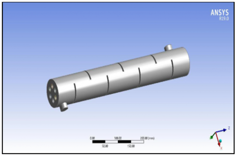
To make a required model of shell and tube heat exchanger, at first it is proposed to design a shell of 600 mm length and 90 mm diameter in the ANSYS design modular software. Then apply the design for 6 number of tubes with required dimension as length 450 mm and diameter 20 mm, inserting the tubes into the shell and define suitable inlet and outlet temperature of cold and hot fluid of shell and tube sides.
Define the cold fluid inlet temperature is kept constant at room temperature 300 K and the inlet of hot fluid is to be kept at 380 K. Apply meshing to the whole component in the ANSYS Fluent and simultaneously check the skewness values for better mesh. After the fine mesh, it can provide better and accurate results. Before going to the solution section, the proposed work is recommended to counterflow shell and tube heat exchangers (conventional tube and helical finned tube surfaces) with varying cold fluid inlet velocities. Fluid outlet temperatures and heat transfer rates can be calculated with suitable formulae. In the solution section it can be visualized and analyze the temperature distribution and heat transfer variation along the components. After the analysis, the setup which gives high heat transfer rates and overall coefficient values is identified and suggested.
In the proposed work, basically the heat exchanger consists of seven (7) baffles arranged through the heat exchanger length of shell in alternating orientations with cut portion facing up and cut portion facing down to create flow paths across the tubes. The heat exchanger with baffles is compared with a model having baffles and finned surfaces on tubes under specifically at different velocities. Modelling of component geometry is done in ANSYS software 19.0 because there is a reduction in complexity in 3D modelling ANSYS type software.
Based on the governing equations of CFD in fluid flow Navier-Stokes equations are applied. The mass, momentum and energy conservation principle are involved in the change of properties based on inputs and outputs.
According to the law of conservation of mass in fluid dynamics, it states that, the amount of mass entering the system is equal to the amount of mass leaving the system and accumulation of mass within the system. The equation is as follows:
$\frac{\partial \rho}{\partial t}+\frac{\partial(\rho u)}{\partial(\rho x)}+\frac{\partial(\rho v)}{\partial(\rho y)}+\frac{\partial(\rho w)}{\partial(\rho z)}=0$ (1)
The Eq. (1) indicates the governing equation of law of conservation of momentum. It is a statement of Newton’s 2nd law. It states that, the resultant force acting on the body and takes place in that direction of force is equal to the rate of change of momentum of a body. The equation is represented like, Force = rate of change of momentum in that direction.
$u \frac{(\rho v)}{(\rho x)}+v \frac{(\rho v)}{(\rho y)}=\frac{\mu}{\rho}\left(\frac{\partial^{2} u}{\partial y^{2}}\right)$ (2)
The Eq. (2) indicates the law of conservation of energy, and it is also a statement of Bernoulli’s equation in fluid dynamics. It states that energy neither be created nor destroyed and only it can change from one form into another form. The equation is as follows:
$\rho C_{p}\left(\frac{\partial T}{\partial t}+u \frac{\partial T}{\partial x}+v \frac{\partial T}{\partial y}+w \frac{\partial T}{\partial z}\right) \phi+$
$\frac{\partial}{\partial x}\left[k \frac{\partial T}{\partial x}\right]+\frac{\partial}{\partial y}\left[k \frac{\partial T}{\partial y}\right]+\frac{\partial}{\partial z}\left[k \frac{\partial T}{\partial z}\right]+$
$u \frac{\partial p}{\partial x}+v \frac{\partial p}{\partial y}+w \frac{\partial p}{\partial z}$ (3)
LMTD (Logarithmic Mean Temperature Difference):
$\mathrm{LMTD}=\frac{\Delta \mathrm{T}_{1}-\Delta \mathrm{T}_{2}}{\ln \left(\Delta \mathrm{T}_{1} / \Delta \mathrm{T}_{2}\right)}$ (4)
Rate of Heat Transfer (Q):
$\mathrm{Q}=\mathrm{m} . \mathrm{C}_{\mathrm{ph}} . \Delta \mathrm{T}_{\mathrm{h}}=\mathrm{m} . \mathrm{C}_{\mathrm{pc}} . \Delta \mathrm{T}_{c}$ (5)
Overall Heat Transfer Coefficient (OHTC):
$\mathrm{Q}=\mathrm{U} . \mathrm{A} .(\Delta \mathrm{T})_{\mathrm{LMTD}}$ (6)
Because the targeted heat transfer in the exchanger occurs over the tube surface, tube geometrical variables are critical in terms of performance. Plain tubes are utilized in most applications. Low finned tubing with a fin height of up to 6.35 mm is utilized when more surface area is necessary to compensate for low heat transfer coefficients on the shell side. Low-height fins improve surface area by two to three times over plain tubes and reduce fouling on the fin side while retaining a reasonable fin efficiency, according to the research. The number of tubes is chosen so that the tube-side velocity for water and similar liquids is between 0.9 and 2.4 m/s and the shell-side velocity is between 0.6 and 1.5 m/s for water and similar liquids. The lower velocity restriction is used to keep fouling at bay, while the maximum velocity limit is used to keep erosion at bay. The flow rate, needed heat transfer, permissible pressure drops, tube support, and flow-induced vibration all influence the baffle type, spacing, and cut. The weight of the heat exchanger increases as the number of baffles increases, even while the heat transfer rate improves. However, the best number of baffles to use is one that strikes a balance between cost, weight, heat transmission rate, and leakage rate. A segmental baffle is a single segmental baffle that is commonly referred to as a segmental baffle. Single segmental baffle spacing can be anything from 1/5 to 1 shell diameter, with 2/5 to 1/2 being ideal. For cleaning the bundle, the minimum baffle spacing is 50.8 mm or 1/5 shell diameter, whichever is greater. Closer spacings than 1/5 shell diameter result in increased leakage, negating the heat transfer advantage of closer spacings. The need to increase the heat transfer in heat exchanger is shown in below tree structure in a concise manner.
Geometric specifications of counterflow shell and tube heat exchanger and the fluid flow inputs are shown in Table 1 and Table 2.
Table 1. Geometric specifications of shell and tube heat exchanger
|
Specifications |
Dimensions |
|
Shell and Tube length |
600 mm |
|
Diameter of the shell |
90 mm |
|
Diameter of the tube |
20 mm |
|
Length of the tube |
450 mm |
|
Shell inlet and Outlet diameter |
30 mm |
|
Number of tubes |
06 |
|
Tube pitch and geometry |
30, Circular |
|
Baffle cut |
50% |
|
Baffle spacing |
75 mm |
|
Baffle thickness |
5 mm |
|
Number of baffles |
7 |
Table 2. Problem statement
|
Working Fluid |
Water |
|
Inlet hot water temp tube side |
380 K |
|
Velocities of cold fluid |
0.0787, 0.1547 (m/s) |
|
Inlet cold water temp shell side |
340 K |
|
Velocity of hot water |
1.5 (m/s) |
A. Geometry modelling
Implementing the design specifications and the geometry of model is created in Design Modeller of ANSYS software 19.0. Particularly this geometry consists of 1shell, 6 tubes and 7 baffles.
Figure 1. Geometric modelling of heat exchanger
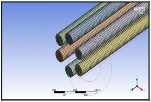
Figure 2. Modelling of heat exchanger tubes
Geometric modelling of heat exchanger, conventional tubes and helical tubes are modelled in ANSYS design modeler are shown in Figure 1, Figure 2 and Figure 3.
Figure 3. Modelling of helical fins on tubes
B. Meshing
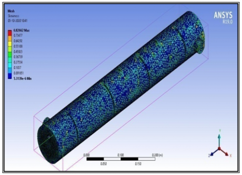
According to its name, the entire component is divided into very small components for the purpose of precise simulation to get accurate results. In the proposed work, a relatively coarse mesh is generated which has tetrahedral and hexahedral cells with quadrilateral and triangular faces at the boundaries.
After several iterations, an edge-sized mesh is generated for optimal results. It should be in a range that satisfies the desired skewness value. The mesh with less skewness value provided the best results.
Figure 4. Mesh generation in a heat exchanger shell
Figure 5. Mesh generation in conventional plain tubes
Figure 6. Mesh generation in heat exchanger tubes with fins
Figure 7. Quality of mesh in shell (in terms of Skewness)
Figure 8. Quality of mesh in tubes
Mesh generation in a heat exchanger shell, conventional tubes and helical finned tubes are done in ANSYS R19.0 and are shown in Figures 4, 5 and 6. Fluid 66 element is chosen for thermal fluid pipe calculations. Once the element selection, boundary conditions fixed, mesh generation is over, then the analysis is done in CFD.
Quality of mesh in shell and tubes are done in ANSYS R19.0 and are shown in Figure 7 and Figure 8.
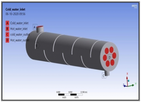
C. Boundary conditions
In the present work, it is proposed to provide boundary conditions at different areas, specifically at two inlets and these inlets are called as velocity inlets, and two outlets called as pressure outlets. The hot fluid velocity is kept as constant and that is at 1.594 m/s, and cold fluid flow is varied in different constant interval velocities of 0.0787 m/s in both conventional and helical finned tube heat exchangers.
Cold fluid inlet temperature is kept as 300 K and hot fluid inlet temperature is considered as 380 K and the surrounding air temperature as 300 K.
In Figure 9, ANSYS R19.0 is used to analyze the boundary conditions of shell and tube heat exchangers.
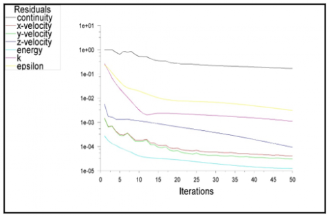
Figure 10 indicates the converged solution of helical finned tube heat exchangers. The continuity, x, y and z-component velocity, energy and k-ε model converged solution is presented against the number of iterations. It indicates that y component velocity has sudden drop up to ten number of iterations and there after the solution has gradual converged solution. k-ε model has shown smooth gradual converged solution.
Figure 9. Boundary conditions
Figure 10. Converging solution of helical finned tubed heat exchangers
ANSYS Design Modeler is used to model the geometry and ANSYS Fluent is used to compute the output performance characteristics of the counterflow shell and tube heat exchanger by varying the inlet velocity of cold fluid on the tube side. The output parameters of LMTD, rate of heat transfer, overall heat transfer coefficient (U) is tabulated in Table 3 and Table 4.
The influence of the output temperatures, heat transfer rates, overall heat transfer coefficient, and effectiveness are examined from the analysis. Based on the simulation results, the best model is identified. Figure 11 shows the variation of LMTD with different velocities at increasing intervals of 0.0787 m/s. This figure can be examined into two strips, in which one strip represents the value of LMTD without fin and the other strip with fin. From the above case, it can be observed that the value of LMTD is increased up to the velocity of 0.233 m/s.
Table 3. Hot and cold fluid temperatures of water at different flow velocities for conventional and finned tube heat exchanger
|
Type of heat exchanger |
Tube side Cold fluid inlet Velocity (m/s) |
Hot fluid temp at inlet (Thi) |
Cold fluid temp at inlet (Tci) |
Hot fluid temp at outlet (Tho) |
Cold fluid temp at outlet (Tco) |
|
Conventional tube |
0.0787 |
380 |
300 |
378.85 |
334.16 |
|
0.0154 0.2330 0.3141 |
380 380 380 |
300 300 300 |
378.54 378.50 377.54 |
321.75 314.52 367.24 |
|
|
Helical finned tube surface |
0.0787 |
380 |
300 |
378.10 |
313.46 |
|
0.0154 0.2334 0.3141 |
380 380 380 |
300 300 300 |
378.20 378.06 377.67 |
314.15 313.43 335.13 |
Table 4. Output performance parameters of the conventional and finned tube heat exchanger
|
Type of heat exchanger |
Tube side Cold fluid inlet Velocity, (m/s) |
LMTD |
Heat transfer rate, Q(W) |
Overall heat transfer coefficient, U (W/m2k) |
Effectiveness ε |
|
Conventional tube |
0.0787 |
60.87 |
119.8 |
8.70 |
0.35 |
|
0.0154 |
68.32 |
299.4 |
19.37 |
0.74 |
|
|
0.2332 0.3141 |
71.83 35.89 |
446.4 1023 |
27.47 126.01 |
0.90 0.96 |
|
|
Helical finned tube surface |
0.0787 |
71.84 |
197.1 |
12.06 |
0.58 |
|
0.0154 |
74.19 |
367.8 |
22.63 |
0.91 |
|
|
0.2336 |
72.17 |
669.51 |
41.0112 |
0.96 |
|
|
0.3141 |
59.78 |
968.54 |
71.6194 |
0.92 |
Figure 11. Variation of LMTD with velocity
The value of LMTD decreased in conventional and helical finned tube surfaces, when the velocity is 0.3121 m/s and the reason is that, when the flow rate traverses from inlet to outlet section along the length of the heat exchanger, the flow changes from laminar to turbulent and this causes the reverse flow in turbulent region at the end of the length of the heat exchanger, while the fluid passing through the baffle spacing in a counterflow heat exchanger. As the flow velocity changes, Reynolds number also changes, and this number dictates the laminar or turbulent flow regime which effects the LMTD value. The fouling factor R at the outlet section contributed for the decrement of LMTD of heat exchanger.
Figure 12 shows the variation of heat transfer rate (HTR) with different velocities at increasing intervals by maintaining the constant interval size 0.0787. The figure can be further examined into two strips at every particular velocity in which one is represents the value of HTR without fin and the other HTR with fin. From this case it can be observed that the value of HTR increased gradually with the increase in velocity both in normal and finned cases.
At every velocity, the value of HRT is slightly higher in finned case than normal cases but in last case at velocity 0.3121 m/s, the one which does not have the fin shown higher value than finned one due to having less temperature difference between hot fluids in finned case than in normal case. At last, the conventional heat exchanger at a velocity 0.3121m/s indicated higher HTR value in the figure.
Figure 12. Variation of heat transfer rate with velocity
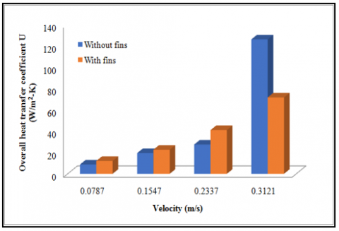
Figure 13. Variation of overall heat transfer coefficient with velocity
Figure 14. Velocity variation with effectiveness
Figure 13 shows the variation of overall heat transfer coefficient (OHTC) with different velocities at a constant interval size of 0.0787. From this case, it is observed that the value of OHTC has increased gradually with increased velocity up to 0.3121 m/s in both normal and helical finned tube cases. Also, at every velocity the value of OHRC is slightly higher in finned case than from the conventional case. But in the last case at velocity 0.3121 m/s the one without fin shown higher value than the conventional one. It is due to the more thermal resistance and less heat transfer rate in finned case than from the normal case.
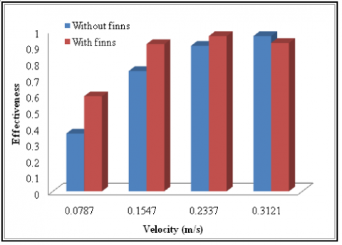
Figure 14 highlighted the graphical variation of effectiveness (ε) with different velocities at a constant increased interval size of 0.0787 m/s. From this case it can be observed that the value of ε is increased for conventional heat exchanger for all the velocities whereas in the finned tube heat exchanger increased the value up to the velocity of 0.2337 m/s and thereafter the effectiveness value is decreased due to fouling factor involvement in heat exchanger. It can be concluded that the effectiveness value is higher for finned tube heat exchanger.
A simulation study is performed on the counterflow STHE using ANSYS Fluent. Present work is compared for two configurations of counterflow heat exchanger (conventional tube and helical finned tube surfaces).
The output parameters of the proposed counterflow heat exchangers, are compared practically with the helical finned tube heat exchanger for high cold fluid velocity resulted a higher rate of heat transfer (Q) and OHTC (U) values than the conventional model. A heat exchanger with helical fins and high cold fluid velocity and low cold-water temperature is recommended for better performance of heat exchanger.
Authors would like to thank the support given by the management for ANSYS - CFD simulation software in Lakireddy Bali Reddy College of Engineering, Mylavaram. Also, the authors would be great thankful to the support given by faculty and friends.
|
LMTD |
Logarithmic Mean Temperature Difference, K |
|
Q |
Heat Transfer Rate, W |
|
STHE |
Shell and Tube Heat Exchanger |
|
Thi |
Hot fluid temperature at inlet, K |
|
Tho |
Hot fluid temperature at outlet, K |
|
Tci |
Cold fluid temperature at inlet, K |
|
Tco |
Cold fluid temperature at outlet, K |
|
U |
Overall Heat Transfer Coefficient (OHTC), W. m-2.K-1 |
|
V |
Velocity, m. s-1 |
[1] Pidaparthi, B., Li, P.W., Missoum, S. (2021). Entropy – based optimization for heat transfer enhancement in tubes with helical fins. Journal of Heat Transfer, ASME, 144(1): 012001. https://doi.org/10.1115/1.4052582
[2] Uosofvand, H., Arani, A.A.A. (2021). Shell- and-tube heat exchangers performance improvement employing hybrid segmental -helical baffles and ribbed tube combination. Journal of the Brazilian Society of Mechanical Sciences and Engineering, Springer, 43: 399. https://doi.org/10.1007/s40430-021-03109-y
[3] Kareem, R. (2017). Optimization of double pipe helical tube heat exchanger and its comparison with straight double tube heat exchanger. Journal of the Institution of Engineers, (India), Springer, Series C, 98: 587-593. https://doi.org/10.1007/s40032-016-0261-x
[4] Abeykoon, C. (2020). Compact heat exchangers-design and optimization with CFD. International Journal of Heat and Mass Transfer, 146: 118766. https://doi.org/10.1016/j.ijheatmasstransfer.2019.118766
[5] El Maakoul, A., Laknizi, A., Saadeddine, S., Ben Abdellah, A., Meziane, M., EI Metoui, M. (2017). Numerical design and investigation of heat transfer enhancement and performance for an annulus with continuous helical baffles in a double-pipe heat exchanger. Energy Conversion and Management, 133: 76-86. https://doi.org/10.1016/j.enconman.2016.12.002
[6] Majidi, D., Alighardashi, H., Farhadi, F. (2018). Experimental studies of heat transfer of air in a double pipe helical heat exchanger. Applied Thermal Engineering, 133: 276-282. https://doi.org/10.1016/j.applthermaleng.2018.01.057
[7] Wen, J., Yang, H.Z., Wang, S., Xu, S.F., Xue, Y.L., Tuo, H.F. (2015). Numerical investigation on baffle configuration improvement of the heat exchanger with helical baffles. Energy Conversion and Management, 89: 438-448. https://doi.org/10.1016/j.enconman.2014.09.059
[8] Tuncer, A.D., Sozen, A., Khanlari, A., Gürbüz, E.Y. (2020). Experimental and numerical analysis of a new modification for enhancing thermal performance of a shell and helically coiled heat exchanger. Applied Thermal Engineering, 184(1). https://doi.org/10.1016/j.applthermaleng.2020.116272
[9] Tian, H., Zhao, T.T., Shi, L.F., Chen, T.Y., Ma, X.N., Zhang, H.F., Shu, G.Q. (2020). Assessment and optimization of exhaust gas heat exchanger with porous baffles and porous fins. Applied Thermal Engineering, 178: 115446. https://doi.org/10.1016/j.applthermaleng.2020.115446
[10] Targui, N., Kahalerras, H. (2013). Analysis of a double pipe heat exchanger performance by use of porous baffles and pulsating flow. Energy Conversion and Management, 76: 43-54. https://doi.org/10.1016/j.enconman.2013.07.022
[11] Pourahamad, S., Pesteei, S.M. (2016). Effectiveness-NTU analysis in a double pipe heat exchanger equipped with wavy strip considering various angles. Energy Conversion and Management, 123: 462-469. https://doi.org/10.1016/j.enconman.2016.06.063
[12] Sheikholeslami, M., Gangi, D.D. (2016). Heat transfer improvement in a piped heat exchanger by means of perforated turbulators. Energy Conversion and Management, 127: 112-123. https://doi.org/10.1016/j.enconman.2016.08.090
[13] Zhang, L., Du, W.J., Wu, J.H., Xing, Y.W. (2012). Fluid flow characteristics for shell side of double pipe heat exchanger with helical fins and pin fins. Experimental Thermal and Fluid Science, 36: 30-43. https://doi.org/10.1016/j.expthermflusci.2011.08.001
[14] Wang, P.F., Jiang, J., Li, S.Y., Luo, X.Y., Wang, S.J., Zhao, W.S. (2019). An investigation of influence factor including different tube bundles on inclined elliptical fin-tube heat exchanger. International Journal of Heat and Mass Transfer, 142: 118448. https://doi.org/10.1016/j.ijheatmasstransfer.2019.118448
[15] Phu, N.M., Trinh, N.T.M. (2016). Modelling and experimental validation for off-design performance of the helical heat exchanger with LMTD correction taken into account. Journal of Mechanical Science and Technology, 30: 3357-3364. https://doi.org/10.1007/s12206-016-0645-0
[16] Mohsen, O.A., Muhammed, M.A.R., Hasan, B.O. (2021). Heat transfer enhancement in a double pipe heat exchanger using different fin geometries in turbulent flow. Iranian Journal of Science and Technology, Transactions of Mechanical Engineering, 45(2): 461-471. https://doi.org/10.1007/s40997-020-00377-2