Subhash Chand* | Prabha Chand
© 2021 IIETA. This article is published by IIETA and is licensed under the CC BY 4.0 license (http://creativecommons.org/licenses/by/4.0/).
OPEN ACCESS
The aim of the present study to improve the performance of solar air heater because of low thermo-physical properties of air. In the current work, an attempt has been made to improve the performance of the heater by employing louvered fins to the absorber plate, as it not only enhances heat transfer coefficient but also improve heat transfer area. The effect of exergy performance on the geometrical parameters of louvered fin i.e., louvered angle, louvered pitch and louvered length has been studied and analyzed. The results are compared to plane solar air heater (PSAH) to evaluate the effectiveness of louvered finned solar air heater (LFSAH). The exergy efficiency of LFSAH is comparatively higher for all the operating conditions except for higher mass flow rate where it may even go below that of PSAH; possibly due to the higher pressure drop and more loss of exergy at high mass flow rate. In addition, the results conclude that for louvered parameters viz., louvered angle 20°, fin pitch to louvered pitch ratio 0.75 and louvered length to louvered pitch ratio 1.25, high exergy performance of SAH is obtained as compared to other louvered parameter values.
solar air heater, exergy efficiency, thermal efficiency, louvered fin, louvered fin parameters
Solar collectors convert solar energy into thermal energy by trapping the solar energy falling on it, to heat a plate which transfers it to a fluid flowing above or beneath it. The fluid may be air or water depending upon the application. When the fluid is air it is termed as SAH which is generally used for moderate temperature drying like harvested grains and sea foods, whereas when it is water the term solar water heater is used; the SAH is less efficient than the latter since air has lower thermal capacity and heat transfer coefficient than water. However, air is much lighter and non-corrosive. Numerous researchers have performed exhaustive work on solar collectors’ performance by pin fin, artificial roughness, connecting fins, packed bed, fins with perforation and baffles etc.
A major contribution by many researchers is available as literature on studies of absorber surfaces. To cite a few, Bahrehmand et al. [1] carried out diagnostic study to evaluate the thermal performance of double and single glass cover SAH. The study concluded a rise in energy and exergy efficiency by employing thin metal sheet and double glass cover. Sabzpooshani et al. [2] evaluated the exergetic performance of baffles attached SAH. They illustrated the effect of baffle parameters and variation of fin, inlet temperature, number of glass cover and thickness of bottom insulation on exergy efficiency. Increasing the baffle width, decreases the baffles distance while increasing the number of fins finally result at low mass flow rate, however at a higher mass flow rate exergy efficiency drops abruptly. Alternatively, increasing the thickness of insulation had no significant effect on the exergy efficiency. Chand and Chand [3] investigated a thermal performance of LFSAH. The study revealed that the thermal performance of LFSAH shows a noticeable enhancement with minimum fin spacing and fin height. Singh et al. [4] determined the artificial roughness SAH using discrete V-down ribs and the results are compared to PSAH. They performed exergy efficiency on various rib roughness parameters such as roughness pitch and gap width, relative roughness pitch, height of roughness, angle of attack. Lalji et al. [5] experimentally performed exergy analysis related to packed bed SAH at various shapes and porosity of matrices. They developed the correlation for Colburn and friction factor as a function of operating and porosity parameters. Chand and Chand [6] investigated a theoretically model of LFSAH. The result showed that the thermal efficiency of LFSAH was 79% higher than the PSAH. Zhang et al. [7] numerically and experimentally analysed the performance of aslit-perforated corrugated plate. The study revealed that the effective efficiency increases up to 67.83% for air velocity increased to 1.14 m/s. Bayrak et al. [8] assessed porous baffles introduced in SAH numerically using exergy and energy analysis methods. Higher values of air temperature rise and collector efficiency was obtained for baffled SAH than non-baffled one. Benli [9] presented an experimental study on five types of air heating solar collectors and provided a solution to overcome the low thermo-physical property of air. Another study on presence of obstacles in solar air heater was accomplished by Esen [10] who experimentally performed the energy and exergy analysis and showed that the higher irreversibility occurs in without obstacles collectors. Gupta and Kaushik [11] compared different geometries of roughness in absorber plate of SAH duct. They reported that V shaped and circular ribs are beneficial for higher values of Reynolds number while chamfered rib-grooves may be used beneficially for lower values of Re. Jafarkazemi and Ahmadifard [12] performed parametric analysis and determined the optimal working conditions of thermal systems of flat plate solar collectors. Kalogirou et al. [13] presented a detailed review on exergy study of various solar thermal systems. Kurtbas and Durmus [14] designed a novel solar air collector by narrowing and expanding it geometrically in shape. Oztop et al. [15] performed extensive review of SAH and concluded that only handful number of research is available on exergy analysis method while majority of the work is available in energy analysis method. Matheswaran et al. [16] evaluate the exergetic performance of single pass double duct jet plate solar air heater. They design the optimum values of jet plate design parameter to find the maximum temperature rise. Hedayatizadeh et al. [17] analyzed the exergetic performance of double pass v-corrugated SAH. They reported that the temperature variations of different components of the given SAH calculated by simulation are compared with their experimental values. Somma et al. [18] carried out exergy modelling and optimized Distributed Energy Systems and successfully curtailed energy cost as well as enhanced the overall exergy efficiency. Yadav and Kaushal [19] analytically attempted to evaluate exergy performance of SAH with protrusions as roughened absorber plate.
Above literatures are based on various types of absorber plate that enhances SAH performance. Some louvered fins specific work, which are used in various engineering applications are available in literature. The corrugated type louvered fin heat exchanger was studied comprehensively by Kraus et al. [20] and Shah and Sakulic [21]. Sahnoun and Webb [22] developed an analytical model to determine the friction factor and heat transfer of louvered fin geometry usually encountered in automotive radiators. Webb and Trauger [23] used dye-injection technique to visualize the flow over louvered fin geometry. They summarized that decreasing the louvered pitch increases the fins per pitch which is imperative to achieve a specific flow efficiency. Vorayos and Kiatsiriroat [24] studied the response of louvered fins to hot gas of lower Reynolds number by observing the effect of design parameters like louver pitch and angle on convective heat transfer.
The literatures have substantial amount of work on SAH with different types of fins likes triangular fins, longitudinal fins, wavy fins etc. The use of these fins results better thermal performance than the PSAH. Despite of this, a detailed workout on louvered fin based on solar air heater is yet to appear in the literature. This paper presents a numerical solution to LFSAH. The objective of this paper is to calculate the exergy efficiency of LFSAH. A mathematical model is devised, which is based on steady flow hypothesis. The thermal conductivity of absorber plate is assumed to be temperature and position independent. The performance is dependent on geometric parameters like louvered pitch, louvered length and louvered angle at various mass flow rates and temperature rise parameter. The governing equation is obtained from the second law of thermodynamics considering a control volume. An iterative procedure is used to solve the governing equations based on Gauss-Seidel method. A homemade computer code based on MATALB programming language is prepared, which simulate the performance of LFSAH.
The current section deals with the past development of solar air heater with various fin arrangements. A systematic study related to previous work, nobility, objective and contents of article is presented here. The second section deals with the mathematical modelling and algorithm for calculation used in LFSAH. The third section presents comprehensive analysis of simulation results obtained for modelled scenario. The relationship between energy efficiency and considered parameter is discussed and validated with the existing literature. A comprehensive concluding remark is furnished at the end of the article.
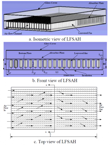
As shown in Figure 1, LFSAH comprises of a flat single glass cover, a louvered fin attached absorbing plate and flat bottom plate with insulation beneath it. A typical louvered fin geometry is demonstrated in Figure 2. The channel created between the bottom plate and the absorbing plate is the channel where the air flows. This air is heated by the solar radiation absorbed by the absorbing plate. Louvered fin attached absorbing plate is along the air flow direction. The reason behind the use of the louvered fin attached absorbing plate are stated as follows. It aids in enhancement of the turbulence in air flow and also the rate of heat transferred across the air flow channel which are crucial for the improvement of efficiency of solar air collector. To measure the improvement of the current model, the performance of LFSAH is compared against that of a PSAH.
Figure 1. Schematic diagram in different views of LFSAH
This study considers some assumptions which simplifies the analysis without complicating the simple physical circumstances. Following are the assumptions considered:
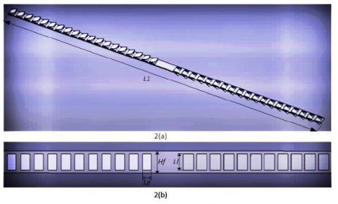
Figure 2. Schematic diagram is shown in 2(a) 3D model of louvered fin & 2(b) Geometrical parameters of louvered fin
2.1 Thermal analysis
The work on thermal analysis of flat plate SAH has been examined by Hottel and Woertz [25], Duffie and Beckman [26]. Bliss Jr [27] considered collector heat removal, Fr, which is the ratio of actual useful heat gain to the useful energy gain if the entire collector absorbing surfaces were maintained at the inlet fluid temperature.
${{Q}_{u}}={{F}_{r}}{{A}_{p}}\left( I{{\alpha }_{1}}{{\tau }_{c}}-{{U}_{L}}\left( {{T}_{fi}}-{{T}_{a}} \right) \right)$ (1)
where, Ap is the area of absorber plate and I is the insolation.
The rate of useful collected energy may be indicated in the same way with the aid of the rise of the enthalpy of air flowing over the collector, such as
${{Q}_{u}}=\overset{\cdot }{\mathop{m}}\,{{C}_{p}}\left( {{T}_{fout}}-{{T}_{i}} \right)$ (2)
Here, Fr shows the heat removal factor.
${{F}_{r}}=\frac{\overset{.}{\mathop{m}}\,{{C}_{p}}}{{{U}_{L}}{{A}_{p}}}\left\{ 1-\exp \left[ -\frac{F{{U}_{L}}{{A}_{p}}}{\overset{.}{\mathop{m}}\,{{C}_{p}}} \right] \right\}$ (3)
$F=\frac{\left(h_{\mathrm{c}, \mathrm{ab}, f}\quad+h_{f f} \phi_{f i n}\right)\left(h_{r, \mathrm{ab}, \mathrm{b}}\quad+h_{\mathrm{c}, \mathrm{ab}, f}\quad+U_{b}\right)+h_{\mathrm{c}, \mathrm{ab}, f} h_{r, \mathrm{ab}, \mathrm{b}}}{\left(\left(U_{t}+h_{\mathrm{c}, f f}\quad+h_{r, \mathrm{ab}, \mathrm{b}}\quad+h_{f f} \phi_{f i n}\right)\left(h_{r, \mathrm{ab}, \mathrm{b}}\quad+h_{f f}\quad+U_{b}\right)\quad-\left(h_{r, \mathrm{ab}, \mathrm{b}}\quad\right)^{2}\right)}$ (4)
where, the effectiveness of fin ffin is defined as,
${{\phi }_{fin}}=1+\left( \frac{{{A}_{f}}}{{{A}_{c}}} \right){{\eta }_{f}}$ (5)
Total surface area of fin and fin efficiency is calculated as,
${{A}_{f}}=\left( 2{{H}_{f}}{{L}_{1}}+2{{H}_{f}}t+\left( 2{{l}_{p}}t+{{l}_{l}}t \right){{N}_{l}}+{{L}_{1}}t \right)n$ (6)
${{A}_{c}}={{L}_{2}}{{L}_{1}}-nt{{L}_{1}}$ (7)
${{\eta }_{f}}=\frac{\tanh \left( m{{H}_{f}} \right)}{m{{H}_{f}}}$ (8)
where, $m=\sqrt{\frac{2 h_{c, f f}}{k_{f i n} t}}$.
$\begin{align} & {{U}_{L}}={{U}_{t}}+\frac{{{h}_{r,ab,b}}{{U}_{b}}}{{{h}_{r,ab,b}}+{{h}_{c,ff}}+{{U}_{b}}} \\ & \text{ }+\frac{1}{F}\left( \frac{{{h}_{c,abf}}{{U}_{b}}}{{{h}_{r,ab,b}}+{{h}_{c,ab,f}}+{{U}_{b}}} \right) \\\end{align}$ (9)
UL and F are the overall heat loss coefficient and collector efficiency factor respectively. The collector efficiency factor is important for any fluid flow rate and design.
The top loss coefficient (Ut) is found by an empirical equation given by Duffie and Beckman [26].
$\begin{align}& {{U}_{t}}={{\left[ \frac{M}{\left( \frac{C}{{{T}_{ab}}} \right){{\left( \frac{{{T}_{ab}}-{{T}_{a}}}{M+f} \right)}^{0.252}}}+\frac{1}{{{h}_{w}}} \right]}^{-1}} \\ & \text{ }+\left[ \frac{\sigma \left( T_{ab}^{2}+T_{a}^{2} \right)\left( {{T}_{ab}}+{{T}_{a}} \right)}{\frac{1}{{{\varepsilon }_{p}}+0.0425M\left( 1-{{\varepsilon }_{p}} \right)}+\frac{2M+f-1}{{{\varepsilon }_{c}}}-M} \right] \\\end{align}$ (10)
where,
$f=\left( \frac{9}{{{h}_{w}}}-\frac{30}{h_{w}^{2}} \right)\left( \frac{{{T}_{a}}}{316.9} \right)\left( 1+0.091M \right)$
$C=204.429{{\left( \cos \beta \right)}^{0.252}}/{{w}^{0.24}}$
where, the bottom loss coefficient is,
${{U}_{b}}=\frac{{{K}_{ins}}}{{{t}_{ins}}}$ (11)
The coefficients of convective heat transfer between the glass cover and atmospheric air are given by Watmuff [28],
${{h}_{w}}=2.8+3.0{{V}_{w}}$ (12)
The coefficient of radiative heat transfer between the bottom plate and absorber plate is,
${{h}_{r,ab,b}}=\frac{\sigma \left( T_{ab}^{2}+T_{b}^{2} \right)\left( {{T}_{ab}}-{{T}_{b}} \right)}{\frac{1}{{{\varepsilon }_{ab}}}+\frac{1}{{{\varepsilon }_{b}}}-1}$ (13)
It is recommended that the Colburn factor (j) is useful to determine the Nusselt number of the air flow $N u_{a b, b}$ in the plate- louvered fins heat exchanger [29].
$\begin{align} & j=0.26712{{\left( {{\operatorname{Re}}_{Lp}} \right)}^{-0.1944}}{{\left( \frac{{{\theta }_{l}}}{90} \right)}^{0.257}}{{\left( \frac{w}{{{L}_{p}}} \right)}^{-0.5177}} \\ & \text{ }{{\left( \frac{{{H}_{f}}}{{{L}_{p}}} \right)}^{-1.9045}}{{\left( \frac{{{L}_{l}}}{{{L}_{p}}} \right)}^{1.7159}}{{\left( \frac{{{L}_{1}}}{{{L}_{p}}} \right)}^{-0.2147}}{{\left( \frac{t}{{{L}_{p}}} \right)}^{-0.05}} \\\end{align}$ (14)
where, t is the thickness of fin, Lp is the louvered pitch, $R e_{L p}$ is the louvered Reynolds number, θl is the louvered angle and Ll is the louvered length.
$N{{u}_{ab,b}}=j\operatorname{Re}{{\Pr }^{0.4}}$ (15)
${{h}_{c,ab,f}}={{h}_{c,b,f}}={{h}_{c,ff}}=\frac{N{{u}_{ab,b}}\quad{{k}_{air}}}{{{D}_{h}}}$ (16)
The pressure drop (Dp) of air through the rectangular channel with louvered fins is calculated as,
$\Delta p=\frac{4f\rho {{L}_{1}}{{V}^{2}}}{2{{D}_{h}}}$ (17)
where, f is the fanning friction factor in the louvered fines could be calculated from the correlation developed by Dong et al. [29].
$\begin{align} & f=0.54486{{\left( {{\operatorname{Re}}_{Lp}} \right)}^{-0.3068}}{{\left( \frac{{{\theta }_{l}}}{90} \right)}^{0.444}}{{\left( \frac{w}{{{L}_{p}}} \right)}^{-0.9925}} \\ & \text{ }{{\left( \frac{{{H}_{f}}}{{{L}_{p}}} \right)}^{0.5458}}{{\left( \frac{{{L}_{l}}}{{{L}_{p}}} \right)}^{-0.2003}}{{\left( \frac{{{L}_{1}}}{{{L}_{p}}} \right)}^{0.0688}} \\\end{align}$ (18)
The air temperature lies in the range of 280K-450K. The correlation used to find the thermo-physical property of air is given by Lin et al. [30] as,
$\begin{align} & \rho =3.9147-0.016082{{T}_{f}}+2.9013\times {{10}^{-5}}T_{f}^{2} \\ & \text{ }-1.9407\times {{10}^{-8}}T_{f}^{3} \\\end{align}$ (19)
$k=\left( \begin{align} & 0.0015215+0.097457{{T}_{f}} \\ & -3.3322\times {{10}^{-5}}T_{f}^{2} \\\end{align} \right)\times {{10}^{-3}}$ (20)
$\mu =\left( 1.6157+0.06523{{T}_{f}}-3.0297\times {{10}^{-5}}T_{f}^{2} \right)\times {{10}^{-6}}$ (21)
where, Tf is the mean temperature of air.
Thermal efficiency of a solar collector is calculated by the ratio of the amount of useful heat gain to the total amount of solar radiation falling on the collector during any period of time.
${{\eta }_{th}}=\frac{{{Q}_{u}}}{I\times {{A}_{c}}}$ (22)
2.2 Exergy performance
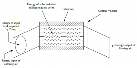
For conducting a qualitative analysis on the collector and also to estimate the system thermal performance in terms of work, it is necessary to perform an analysis based on the second law of thermodynamics. For this, consider air is a perfect gas and negligible change in the potential and kinetic energy, the general exergy balance for LFSAH by considering a control volume as shown in Figure 3.
Figure 3. Exergy flow diagram of LFSAH
$\overset{.}{\mathop{E{{x}_{in}}}}\,-\overset{.}{\mathop{E{{x}_{out}}}}\,+\overset{.}{\mathop{E{{x}_{s}}}}\,+\overset{.}{\mathop{E{{x}_{w}}}}\,=\overset{.}{\mathop{E{{x}_{dest}}}}\,$ (23)
${{\overset{.}{\mathop{Ex}}\,}_{s}}=\left( 1-\frac{{{T}_{a}}}{{{T}_{s}}} \right)\overset{.}{\mathop{{{Q}_{s}}}}\,$ (24)
where, Ts is the sun temperature which is approximately ¾ of the blackbody temperature of the Sun.
${{\overset{.}{\mathop{Ex}}\,}_{in}}=\dot{m}{{C}_{p}}\left[ \left( {{T}_{fi}}-{{T}_{a}} \right)-{{T}_{a}}ln\left( \frac{{{T}_{fi}}}{{{T}_{a}}} \right) \right]$ (25)
$\begin{align} & {{\overset{.}{\mathop{Ex}}\,}_{out}}={{\overset{.}{\mathop{Ex}}\,}_{mass\text{ }\!\!~\!\!\text{ }out}} \\ & \text{ }=\dot{m}{{c}_{p}}\left[ \left( {{T}_{fout}}-{{T}_{a}} \right)-{{T}_{a}}ln\left( \frac{{{T}_{fout}}}{{{T}_{a}}} \right) \right] \\\end{align}$ (26)
$\overset{.}{\mathop{E{{x}_{w}}}}\,=\frac{{{T}_{a}}}{{{T}_{fi}}}{{W}_{p}}$ (27)
where, Wp, the pump required work.
${{W}_{p}}=\frac{\dot{m}\Delta p}{\rho {{\eta }_{p}}}$
where, ηp, the pump efficiency is taken equal to 0.85.
Substituting the Eqns. (24), (25), (26) and (27) in Eq. (19).
$\begin{align} & \left( 1-\frac{{{T}_{a}}}{{{T}_{s}}} \right)\overset{.}{\mathop{{{Q}_{s}}}}\,+\dot{m}{{C}_{p}}\left[ \left( {{T}_{fi}}-{{T}_{a}} \right)-{{T}_{a}}ln\left( \frac{{{T}_{fi}}}{{{T}_{a}}} \right) \right]- \\ & \dot{m}{{C}_{p}}\left[ \left( {{T}_{fout}}-{{T}_{a}} \right)-{{T}_{a}}ln\left( \frac{{{T}_{fout}}}{{{T}_{a}}} \right) \right]+\frac{{{T}_{a}}}{{{T}_{fi}}}{{W}_{p}}={{\overset{.}{\mathop{Ex}}\,}_{dest}} \\\end{align}$ (28)
Simplifying the Eq. (28)
$\begin{align} & \left( 1-\frac{{{T}_{a}}}{{{T}_{s}}} \right)I\left( \tau \alpha \right){{A}_{c}}-\dot{m}{{C}_{p}}\left( {{T}_{fout}}-{{T}_{fi}} \right) \\ & +\dot{m}{{C}_{p}}{{T}_{a}}ln\left( \frac{{{T}_{fout}}}{{{T}_{fi}}} \right)+\frac{{{T}_{a}}}{{{T}_{fi}}}{{W}_{p}}={{\overset{.}{\mathop{Ex}}\,}_{dest}} \\\end{align}$ (29)
Exergy efficiency of SAH as a function of net output exergy of the system can be defined as,
${{\eta }_{II}}=\frac{\dot{m}{{C}_{p}}\left[ \left( {{T}_{fout}}-{{T}_{fi}} \right)-{{T}_{a}}ln\left( \frac{{{T}_{fout}}}{{{T}_{fi}}} \right)+\frac{{{T}_{a}}}{{{T}_{fi}}}{{W}_{p}} \right]}{\left( 1-\frac{{{T}_{a}}}{{{T}_{s}}} \right)I\left( \tau \alpha \right){{A}_{c}}}$ (30)
2.3 Calculation procedure
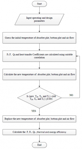
A computational code was scripted for solving the above equations. The geometric parameters, operating condition and material properties are given in Table 1. The iterative procedure is:
Figure 4. Exergy flow chart for LFSAH
The solution procedure in form of a flow chart is represented in Figure 4.
The exergetic performance of the LFSAH for several mass flow rate, louvered fin parameters, temperature rise parameters and insolation are discussed analytically in this section. Fixed and design parameters are listed in Table 1.
Table 1. Operating and system parameters used in analytical study
|
Input data |
Numerical Values |
|
Collector length (L1) Collector width(L2) Duct height(H) Fin spacing(w) Fin height (Hf) Fin thickness (t) Louvered Pitch (Lp) Louvered length (Ll) Louvered angle (θl) Thermal conductivity of fin (Kf), Wind velocity (Vw) Ambient temperature (Ta) Inlet temperature (Ti) Absorptivity of glass (αg) Absorptivity of absorber plate (αab) Emissivity of absorber plate (εab) Emissivity of bottom plate (εb) Emissivity of glass (εg) mass flow rate(ṁ) |
1.2 m 0.6 m 0.03 m 0.015m 0.028 m 0.0025 m 0.01-0.025 m 0.01 -0.025 m $10^{\circ}-40^{\circ}$ 50 W/mK 2.5 m/s 300 K 303 K 0.11 0.96 0.95 0.95 0.90 0.0027-0.0694 kg/s |
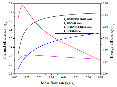
Figure 5. Variation of thermal efficiency and exergy efficiency with mass flow rate
Figure 5 illustrates the effect of mass flow rate on exergy and thermal efficiency for louvered parameters of θl, Ll/Lp and w/Lp are 20°, 1.25 and 0.75 respectively and it is compared with PSAH. An overall glance at the graph reveals that both the efficiencies viz., thermal and exergy efficiency of LFSAH is quite higher than PSAH. Thermal efficiency shows drastic increase for lower values of mass flow rate after which the increase is not very prominent but shows a definite increase howsoever small it may be. On other hand, exergy efficiency suddenly rises for extremely small value of mass flow rate viz., 0.005 kg/sec after which it drops with further rise in mass flow rate. However, though the exergy efficiency for LFSAH is decreasing, it is still pretty high than exergy efficiency of PSAH until the mass flow rate is 0.066 kg/sec. Post this value, the exergy efficiency of LFSAH becomes even less than that of PSAH. The solar radiation absorbed by the absorber leads to higher exergy loss which results into lower values of exergy efficiency irrespective of mass flow rate values. This effect is much pronounced at higher mass flow rates where the exergy efficiency becomes negative. Higher mass flow rate requires higher pump work; this pump work surpasses the exergy of heat energy collected. Consequently, the numerator of exergy efficiency, which is the difference of heat energy collected and pumping power tends to become negative and thereby resulting into a negative exergy efficiency. The comparative performance prediction of the PSAH and LFSAH investigated range of air flow rate is presented in Table 2.
Table 2. Theoretical predictions of temperature rise parameter, thermal efficiency and exergy efficiency as a function of air flow rate
|
Mass Flow rate (kg/s) |
Plane solar air heater |
Louvered finned solar air heater |
||||
|
∆T/I |
ηex |
ηth |
∆T/I |
ηex |
ηth |
|
|
0.0027 |
0.0419 |
0.012 |
0.150 |
0.087 |
0.047 |
0.324 |
|
0.0083 |
0.0273 |
0.015 |
0.280 |
0.053 |
0.056 |
0.579 |
|
0.0138 |
0.0214 |
0.015 |
0.352 |
0.037 |
0.047 |
0.665 |
|
0.0194 |
0.0180 |
0.015 |
0.400 |
0.029 |
0.041 |
0.707 |
|
0.025 |
0.0157 |
0.015 |
0.435 |
0.024 |
0.035 |
0.732 |
|
0.0305 |
0.0141 |
0.014 |
0.462 |
0.020 |
0.031 |
0.748 |
|
0.0361 |
0.0129 |
0.014 |
0.484 |
0.018 |
0.028 |
0.759 |
|
0.0416 |
0.0119 |
0.014 |
0.502 |
0.016 |
0.025 |
0.768 |
|
0.0472 |
0.0111 |
0.013 |
0.517 |
0.015 |
0.022 |
0.775 |
|
0.0527 |
0.0105 |
0.013 |
0.530 |
0.013 |
0.019 |
0.780 |
|
0.0583 |
0.0099 |
0.013 |
0.542 |
0.013 |
0.017 |
0.784 |
|
0.0638 |
0.0095 |
0.012 |
0.552 |
0.012 |
0.014 |
0.788 |
|
0.0694 |
0.0091 |
0.012 |
0.561 |
0.011 |
0.011 |
0.791 |
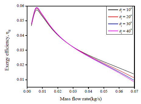
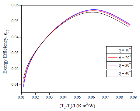
Figure 6 shows influence of mass flow rate on exergy efficiency with respect to louvered angle 10°, 20°, 30° and 40°. For mass flow rate up to 0.01 kg/sec, the exergy efficiency initially shows a sharp increase and then starts dropping for further values of mass flow rate. Another noticeable fact is the sequence of louvered angle which affects the exergy efficiency. The exergy efficiency for mass flow rate till 0.03kg/sec is observed to increase for louvered angle from 10° to 40°, while when mass flow rate is greater than 0.03kg/sec, the sequence is reversed Figure 7 shows variation of exergy efficiency with temperature rise parameter for louvered angles 10°, 20°, 30° and 40°. The exergy efficiency increases until temperature rise parameter is 0.067 (K m2/W). Post this value, the reduction starts. Also, it is clearly noticeable that for lesser temperature rise parameter the exergy efficiency shows a subtle increase with decreasing louvered angle. However, the exergy efficiency increases with increasing values louvered angle for greater values of temperature rise parameter. Exergy efficiency of LFSAH is significantly higher than that of PSAH at all louvered angle. However, an increase in louvered angle has only a mediocre increase in exergy efficiency. Another downfall of high louvered angle can be pinned on the associated increase in pressure drop. As louvered angle increases, the obstruction to air flow increases leading to exergy loss an increase in pressure drop which finally leads to increase in pumping work. Thus, it is preferable to restrict the louvered angle to 20°.
Figure 6. Variation of exergy efficiency with mass flow rate at different louvered angles
Figure 7. Variation of exergy efficiency with temperature rise at different louvered angle
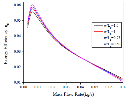
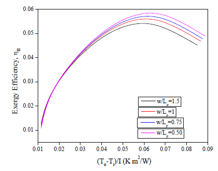
Figure 8 shows influence of mass flow rate on exergy efficiency with respect to fin spacing to louvered pitch ratio (w/Lp) 1.5, 1, 0.75 and 0.50 at constant louvered angle 20° and insolation I= 900W/m2 for mass flow rate up to 0.01 kg/sec, the exergy efficiency shows a sharp increase and then starts dropping for further values of mass flow rate. Another noticeable fact is that for mass flow rate less than 0.045 kg/sec, exergy efficiency increases in sequence as: 1.5>1>0.75>0.50. When mass flow rate is greater than 0.045kg/sec the sequence is reversed. Figure 9 shows deviation of exergy efficiency using temperature rise parameter for various ratios of fin spacing to louvered pitch (w/Lp) 1.5, 1, 0.75, and 0.50. The exergy efficiency increases until temperature rise parameter is 0.067 (K m2/W). Post this value, it starts dropping. Also, it is clearly noticeable that for smaller temperature rise parameter the exergy efficiency shows a subtle increase with increasing fin spacing to louvered pitch ratio. However, the exergy efficiency increases with decreasing the values of fin spacing to louvered pitch ratio for high values of temperature rise parameter. Exergy efficiency of LFSAH is significantly higher than that of PSAH at all fin spacing to louvered pitch ratio. As louvered pitch increases i.e., at lower w/Lp ratio, the flow of air is steered effectively by the louvered fins. This increases the effective area of heat transfer ultimately enhancing the heat transfer rate. Conversely, as louvered pitch decreases i.e., at higher w/Lp ratio, it becomes increasingly difficult for louvered fins to steer the air flow to effectively increase the area of heat transfer and hence it leads to negligible enhancement in heat transfer rate.
Figure 8. Variation of exergy efficiency with mass flow rate at different w/Lp ratio
Figure 9. Variation of exergy efficiency with temperature rise parameters at w/Lp ratio
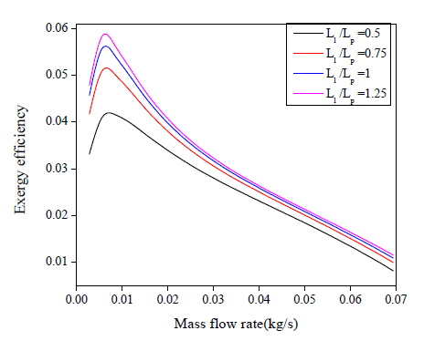
Figure 10. Variation of exergy efficiency with mass flow rate at different louvered length to louvered pitch ratio (Ll/Lp)
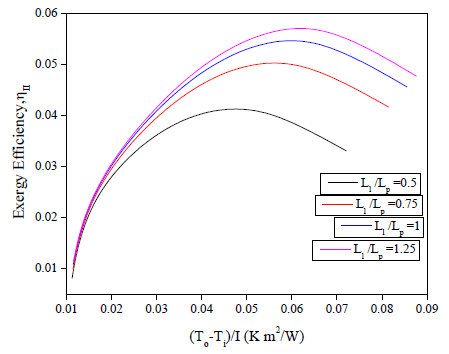
Figure 11. Variation of exergy efficiency with temperature rise parameter at different louvered length to louvered pitch ratio (Ll/Lp)
Figure 10 shows the variation of mass flow rate on exergy efficiency with respect to louvered length to louvered pitch ratio (Ll/Lp) of 0.50, 0.75, 1 and 1.25 and at constant louvered angle $20^{\circ}$ and insolation I= 900W/m2. Thus, it can be observed that for mass flow rate up to 0.01 kg/sec, the exergy efficiency shows a sharp increase and then starts dropping for further increasing of mass flow rate for all value of louver length to louvered pitch ratio. The results revealed that the increase in Ll/Lp ratio increasing in exergy efficiency for all rang of mass flow rate. Figure 11 shows deviation of exergy efficiency relative to temperature rise parameter for various louvered length to louvered pitch ratio (Ll/Lp) of 0.50, 0.75, 1 and 1.25 and at constant louvered angle $20^{\circ}$ and insolation I= 900W/m2. The exergy efficiency increases until temperature rise parameter is 0.067 (K m2/W). Afterwards, it starts dropping. Also, it is clearly noticeable that for lesser magnitudes of temperature rise parameter the exergy efficiency shows a subtle increase with increasing louvered pitch to louvered pitch ratio. However, the exergy efficiency shows rise with increasing the values of louvered length to louvered pitch ratio for all values of temperature rise parameter. Exergy efficiency of LFSAH is significantly higher than that of PSAH at all louvered length to louvered pitch ratio. As louvered length increases i.e., at higher Ll/Lp ratio, the flow of air is steered effectively by the louvered fins. This increases the effective area of heat transfer ultimately enhancing the heat transfer rate.
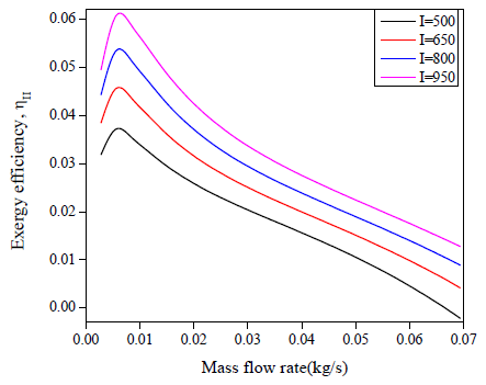
Figure 12. Variation of exergy efficiency with mass flow rate for different insolation
Figure 12 shows exergy efficiency with varying mass flow rate for various values of solar intensity. Exergy efficiency reaches its peak value at extremely lower values of mass flow rate and then starts dropping for entire remaining range of mass flow rate with higher efficiency for the highest value of solar intensity. Figure 13 illustrates plot of exergy efficiency with temperature rise parameter for several values of solar intensity. At lower values, exergy efficiency shows an abrupt increase, after 0.02 (K m2/W) the rise in efficiency becomes gradual and reaches to its peak at 0.06 (K m2/W) after which it drops gradually. Also, it is quite obvious that increase in solar intensity will lead to rise in exergy efficiency which is clearly evident from Figure 13. This happens due to the fact that the lower insolation exergy destruction is high.
Figure 13. Variation of exergy efficiency with temperature rise parameter for different insolation
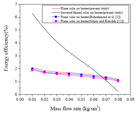
For validation purpose, experimental results of Bahrehmand et al. [1] and Gupta and Kaushik [11] have been compared with present results to demonstrate variations in exergy efficiency of PSAH and LFSAH under study of similar operating parameters and configuration as shown in the Figure 14. The mean deviations of exergy efficiency of plane solar air heater (in present study) and plane solar air heater Bahrehmand et al. [1] and Gupta and Kaushik [11] have been compared and a variation of ±6.65% and ±12.69% has been calculated. As the mass flow rate per unit area increases from 0.01kg/sm2 to 0.08kg/sm2, the average enhancement in LFSAH with respect to PSAH was found to be 1.99 times. These results conclude a good accord between the present analytical result and the results by Bahrehmand et al. [1] and Gupta and Kaushik [11]. Thus, the current analytical work can now be extended to the problem of louvered fin presented in this paper with greater confidence.
Figure 14. Comparison of exergy efficiency of present work with Bahrehmand et al. [1] and Gupta and Kaushik [11]
Prediction of exergy efficiency of LFSAH has been carried out analytically considering operating parameters like mass flow rate (ṁ), temperature rise and geometrical parameter like louvered length, louvered pitch and louvered angle. On the basis of above results and discussion, the following conclusions were drawn:
|
A |
Area: Ap (absorber plate), Ac (Collector), m2 |
|
Cp |
Specific heat (J/kgK) |
|
Dh |
Hydraulic diameter (m) |
|
f |
friction factor |
|
F |
Collector efficiency factor |
|
Fr |
Heat removal factor |
|
H |
duct height, m |
|
Hf |
fins height, m |
|
hr,ab,b |
Radiative heat transfer coefficient between absorber plate and bottom plate, W/m2K |
|
hc |
Convective heat transfer: hc,ab,f (absorber plate and air stream), hc,f,b (bottom plate and air stream), W/m2K |
|
j |
Colburn factor |
|
N |
Number of fins |
|
Qu |
Useful heat gain (W) |
|
ReL |
Reynolds number based on louver |
|
Re |
Reynolds number |
|
Ta |
Ambient temperature K |
|
T |
Mean temperature: Tb (bottom plate), Tf (fluid), Tab (absorber plate), K |
|
t |
Fin thickness (m) |
|
Ub |
Bottom loss coefficient |
|
UL |
Top loss coefficient (W/m2K) |
|
Vw |
wind velocity (m/s) |
|
Greek symbols |
|
|
α |
Absorptivity |
|
ε |
Emissivity |
|
ρ |
Density of air (kg/m3) |
|
σ |
Stefan’s constant (5.67x10⁻⁸Wm2 K-4) |
|
$\Delta p$ |
Pressure drop (N/m2) |
|
θl |
Louvered angle |
|
Subscripts |
|
|
PSAH |
Plane solar air heater |
|
LFSAH |
louvered finned solar air heater |
|
SAH |
solar air heater |
[1] Bahrehmand, D., Ameri, M., Gholampour, M. (2015). Energy and exergy analysis of different solar air collector systems with forced convection. Renewable Energy, 83: 1119-1130. https://doi.org/10.1016/j.renene.2015.03.009
[2] Sabzpooshani, M., Mohammadi, K., Khorasanizadeh, H. (2014). Exergetic performance evaluation of a single pass baffled solar air heater. Energy, 64: 697-706. https://doi.org/10.1016/j.energy.2013.11.046
[3] Chand, S., Chand, P. (2018). Performance evaluation of solar air heater equipped with louvered fins. International Journal of Heat and Technology, 36(2): 741-751. https://doi.org/10.18280/ijht.360241
[4] Singh, S., Chander, S., Saini, J.S. (2011). Heat transfer and friction factor correlations of solar air heater ducts artificially roughened with discrete V-down ribs. Energy, 36(8): 5053-5064. https://doi.org/10.1016/j.energy.2011.05.052
[5] Lalji, M.K., Sarviya, R.M., Bhagoria, J.L. (2012). Exergy evaluation of packed bed solar air heater. Renewable and Sustainable Energy Reviews, 16(8): 6262-6267. https://doi.org/10.1016/j.rser.2012.04.024
[6] Chand, S., Chand, P. (2018). Parametric study on the performance of solar air heater equipped with louvered fins. Journal of Mechanical Science and Technology, 32(8): 39653973. https://doi.org/10.1007/s12206-018-0747-y
[7] Zhang, H., Ma, X., You, S., Wang, Y., Zheng, X., Ye, T., Zheng, W., Wei, S. (2018). Mathematical modeling and performance analysis of a solar air collector with slit-perforated corrugated plate. Solar Energy, 167: 147-157. https://doi.org/10.1016/j.solener.2018.04.003
[8] Bayrak, F., Oztop, H.F., Hepbasli, A. (2013). Energy and exergy analyses of porous baffles inserted solar air heaters for building applications. Energy and Buildings, 57: 338-345. https://doi.org/10.1016/j.enbuild.2012.10.055
[9] Benli, H. (2013). Experimentally derived efficiency and exergy analysis of a new solar air heater having different surface shapes. Renewable Energy, 50: 58-67. https://doi.org/10.1016/j.renene.2012.06.022
[10] Esen, H. (2008). Experimental energy and exergy analysis of a double-flow solar air heater having different obstacles on absorber plates. Building and Environment, 43(6): 1046-1054. https://doi.org/10.1016/j.buildenv.2007.02.016
[11] Gupta, M.K., Kaushik, S.C. (2009). Performance evaluation of solar air heater for various artificial roughness geometries based on energy, effective and exergy efficiencies. Renewable Energy, 34(3): 465-476. https://doi.org/10.1016/j.renene.2008.06.001
[12] Jafarkazemi, F., Ahmadifard, E. (2013). Energetic and exergetic evaluation of flat plate solar collectors. Renewable Energy, 56: 55-63. https://doi.org/10.1016/j.renene.2012.10.031
[13] Kalogirou, S.A., Karellas, S., Badescu, V., Braimakis, K. (2016). Exergy analysis on solar thermal systems: A better understanding of their sustainability. Renewable Energy, 85: 1328-1333. https://doi.org/10.1016/j.renene.2015.05.037
[14] Kurtbas, I., Durmus̨, A. (2004). Efficiency and exergy analysis of a new solar air heater. Renewable Energy, 29(9): 1489-1501. https://doi.org/10.1016/j.renene.2004.01.006
[15] Oztop, H.F., Bayrak, F., Hepbasli, A. (2013). Energetic and exergetic aspects of solar air heating (solar collector) systems. Renewable and Sustainable Energy Reviews, 21: 59-83. https://doi.org/10.1016/j.rser.2012.12.019
[16] Matheswaran, M.M., Arjunan, T.V., Somasundaram, D. (2018). Analytical investigation of solar air heater with jet impingement using energy and exergy analysis. Solar Energy, 161: 25-37. https://doi.org/10.1016/j.solener.2017.12.036
[17] Hedayatizadeh, M., Sarhaddi, F., Safavinejad, A., Ranjbar, F., Chaji, H. (2016). Exergy loss-based efficiency optimization of a double-pass/glazed v-corrugated plate solar air heater. Energy, 94: 799-810. https://doi.org/10.1016/j.energy.2015.11.046
[18] Di Somma, M., Yan, B., Bianco, N., Graditi, G., Luh, P.B., Mongibello, L., Naso, V. (2015). Operation optimization of a distributed energy system considering energy costs and exergy efficiency. Energy Conversion and Management, 103: 739-751. https://doi.org/10.1016/j.enconman.2015.07.009
[19] Yadav, S., Kaushal, M. (2014). Exergetic performance evaluation of solar air heater having arc shape oriented protrusions as roughness element. Solar Energy, 105: 181-189. https://doi.org/10.1016/j.solener.2014.04.001
[20] Kraus, A.D., Aziz, A., Welty, J. (2002). Extended Surface Heat Transfer. John Wiley & Sons.
[21] Shah, R.K., Sakulic, D.P. (2003). Fundamentals of Heat Exchanger Design. John Wiley & Sons.
[22] Sahnoun, A., Webb, R.L. (1992). Prediction of heat transfer and friction for the louver fin geometry. Journal of Heat Transfer, 114(4): 893-900. https://doi.org/10.1115/1.2911898
[23] Webb, R.L., Trauger, P. (1991). How structure in the louvered fin heat exchanger geometry. Experimental Thermal and Fluid Science, 4(2): 205-217. https://doi.org/10.1016/0894-1777(91)90065-Y
[24] Vorayos, N., Kiatsiriroat, T. (2010). Thermal characteristics of louvered fins with a low-Reynolds number flow. Journal of Mechanical Science and Technology, 24(4): 845-850. https://doi.org/10.1007/s12206-010-0310-y
[25] Hottel, H.C., Woertz, B.B. (1942). The performance of flat plate solar heat collector. Transactions of ASME, 64: 91-104.
[26] Duffie, J.A., Beckman, W.A. (1980). Solar Engineering of Thermal Processes. Wiley, New York.
[27] Bliss Jr, R.W. (1959). The derivations of several “plate-efficiency factors” useful in the design of flat-plate solar heat collectors. Solar Energy, 3(4): 55-64. https://doi.org/10.1016/0038-092X(59)90006-4
[28] Watmuff, J.H., Charters, W.W.S., Proctor, D. (1977). Solar and wind induced external coefficients-solar collectors. Cooperation Mediterraneenne pour l'Energie Solaire, 56.
[29] Dong, J., Chen, J., Chen, Z., Zhang, W., Zhou, Y. (2007). Heat transfer and pressure drop correlations for the multi-louvered fin compact heat exchangers. Energy Conversion and Management, 48(5): 1506-1515. https://doi.org/10.1016/j.enconman.2006.11.023
[30] Lin, W., Gao, W., Liu, T. (2006). A parametric study on the thermal performance of cross-corrugated solar air collectors. Applied Thermal Engineering, 26(10): 1043-1053. https://doi.org/10.1016/j.applthermaleng.2005.10.005