Sarawut Sirikasemsuk | Songkran Wiriyasart | Ruktai Prurapark | Nittaya Naphon | Paisarn Naphon*
© 2021 IIETA. This article is published by IIETA and is licensed under the CC BY 4.0 license (http://creativecommons.org/licenses/by/4.0/).
OPEN ACCESS
We investigated the results of the cooling performance of the pulsating water/nanofluids flowing in the thermoelectric cooling module for cooling electric vehicle battery systems. The experimental system was designed and constructed to consider the effects of the water block configuration, hot and cold side flow rates, supplied power input, and coolant types on the cooling performance of the thermoelectric module. The measured results from the present study with the Peltier module are verified against those without the thermoelectric module. Before entering the electric vehicle battering system with a Peltier module, the inlet coolant temperatures were 2.5-3.5℃ lower than those without the thermoelectric system. On the hot side, the maximum COP of the thermoelectric cooling module was 1.10 and 1.30 for water and nanofluids as coolant, respectively. The results obtained from the present approach can be used to optimize the battery cooling technique to operate in an appropriate temperature range for getting higher energy storage, durability, lifecycles, and efficiency.
electric vehicle battery, thermoelectric cooling module, pulsating flow, nanofluid
Due to higher power density, lower weight, and a small area that results in higher generated heat, choosing a cooling technique for electronic battery modules in the designated temperature is warranted for obtaining higher energy storage, durability, and efficiency, especially for the modern battery pack. There are many advantages to this: high reliability, small size, stationary parts, lightweight, and without coolant. Thermoelectric cooling modules have been considered for various applications. Gould et al. [1] studied the power generation with the cooling system of the standard desktop computer. Martínez et al. [2] proposed a novel thermoelectric cooling solution with zero energy consumption. Kinsella et al. [3] designed a prototype electrical generator using a thermoelectric module. Suh et al. [4] used a thermoelectric system for cooling an electric vehicle's energy storage system. Huang et al. [5] studied a power generator with a loop heat pipe. Borisyuk et al. [6] considered the effect of film properties based on metal nanoclusters (Au, Pd, Pt) on thermoelectric performance. Kiflemariam and Lin [7] analyzed the geometric and system parameters affecting thermoelectric performance. Zhang et al. [8] estimated the internal battery temperature using a novel simplified thermoelectric model. Atouei et al. [9] experimentally investigated a two-stage Peltier generator system. Liu et al. [10] applied the generalized predictive control couple with a thermoelectric module to charge a LiFePO4 battery. Rao et al. [11] proposed a liquid cooling system for the electric battery. Chen et al. [12-16] developed the thermal efficiency of the battery pack cooling system with parallel/ U-type/ secondary vent air-cooled BTMS. Lu et al. [17] studied the channel width, and coolant flow rate on the thermal characteristics of storage arranged battery packs. Zhao et al. [18] applied a thermal-lumped treatment to analyze a single battery’s heat generation. Arora [19] installed a temperature controller near a specified state to identify the potential candidate. Cao et al. [20] proposed a new heat pipe-assisted thermoelectric generator for the automobile heat recovery system. Daghigh and Khaledian [21] applied the cooling and heating systems with thermoelectrics in the photovoltaic collector. Ebrahimi and Derakhshan [22] investigated a combined fuel cell and thermoelectric cooler. Li et al. [23] developed the air conditioning system’s hybrid model with a thermoelectric cooling system. Muralidhar et al. [24] applied thermoelectric generators to an electric vehicle. Song et al. [25] used phase materials and a semiconductor thermoelectric device cooling system for a thermal management system. Wang et al. [26] constructed a new thermoelectric hybrid battery system to utilize FeS2 battery waste. Abedi et al. [27] studied a thermoelectric generator based on a catalytic combustor to approach electrical output. Cai et al. [28] considered the relevant parameters on the energy and entropy performance of TAC and TSC systems. Comamala et al. [29] proposed using an ATEG in an electric vehicle. Dan et al. [30] applied the micro heat pipe in the thermal cooling system. Darcovich et al. [31] combined the micro and macro-scale cooling systems in the battery pack’s thermal state. Dufo-López et al. [32] optimized the supplied electricity in off-grid systems using a thermoelectric generator. Fotso et al. [33] analyzed a solar thermoelectric generator’s thermal performance with a vortex tube for hybrid vehicles. Jiang et al. [34] studied a thermoelectric cooler’s performance in the thermal management of a cylindrical battery module. Kwan et al. [35] reviewed the energy management method for a fuel cell thermoelectric hybrid system. Lan et al. [36] studied a bifunctional thermoelectric generator that was applied in vehicle engines. Lyu et al. [37] studied the battery thermal cooling technique for emerging electric vehicles. Massaguer et al. [38] analyzed the behavior of an ATEG in a mid-size vehicle under a world harmonized light vehicle test procedure. Sulaiman et al. [39] combined the thermoelectric generator, heat pipe, and heat sink system in the heat recovery process. Shiriaev et al. [40] used an AC/DC converter in the thermoelectric generator system of automotive. Finally, Toan et al. [41] studied the effectiveness of a thermal electrochemical generator with nano-flow channels. It is clear that air cooling as a technique is not appropriate for reducing battery temperature. This is due to the limitation of air’s thermal properties. As a result, cooling systems have been continuously developed for obtaining higher thermal efficiency using different channel configurations [42-45] or by changing coolant. There are many applications of thermal cooling systems using nanofluid applications as a working fluid. Nanofluid has more heat capability. Many papers presented on the application of different nanofluids in the cooling systems; photovoltaic thermal system [46], flow regimes [47], automotive radiator [48], and tube convective heat transfer enhancement [49]. In addition, Ambreem et al. [50] and Babar and Ali [51] used nanofluid flowing through the Airfoil shaped pin-fin heat sink to determine thermal efficiency.
The literature review above shows that many works have considered the thermoelectric applications or thermal cooling of the electric vehicle battery module with different coolant types. Although the air-cooling technique is lower in weight, its cooling efficiency is low. The liquid cooling techniques result in higher thermal efficiency but are more complicated systems and have higher energy requirements. Generally, water and oil are mostly used as coolant in thermal cooling systems. In addition, nanofluid applications as a coolant in heat transfer augmentation have provided excellent heat transfer enhancements. However, no works are reported on the thermoelectric applications for the electric vehicle battery module, especially with nanofluids in pulsating flow conditions—some techniques for decreasing the operating temperature of the battery pack. The working fluid is cooled by the TCM, which reduces the inlet temperature, before flowing into the battery pack with greater cooling efficiency. The objective of the current study is to consider the thermal performance of the thermoelectric cooling module with water/nanofluids in a pulsating flow for an electric vehicle battery system. The effects of the relevant parameters, including the water block configurations, the flow rate of both sides of the working fluids, supplied power to the Peltier plate, and different coolants on the thermoelectric cooling module’s cooling efficiency, were investigated.
2.1 Experimental apparatus
Figure 1 shows the experimental apparatus of the pulsating water/nanofluids flowing in the cooling module of the electric vehicle battery system. The system is classified by two main loops: the hot side coolant loop for the hot side of the Peltier module and the cold side water loop for the cold side of the Peltier module. The hot side water/nanofluid’s loop consists of a sonicated system, water pump, peristaltic pump, and radiator. The water/nanofluids flow out of the sonicated bath and into the peristaltic pump and then flow into the hot side of the Peltier cooling system before returning to the sonicated bath. The cold side loop consists of an electric vehicle battery system, radiator, flow meter, pump, and storage tank. Two water pumps (Model: MD-30R) operate in the system to circulate two side coolants. The coolant flows out of the water tank and into the cold side to reduce its temperature. It then flows through the radiator to cool the environment before returning to the storage tank.
Figure 1. Schematic illustration of the thermoelectric cooling system for the battery module
2.2 Nanofluids preparation
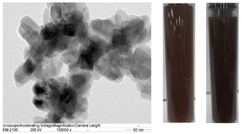
Experiment: Two different TiO2 nanofluid concentrations (0.005% and 0.015% by volume) were prepared for the present study by being suspended in the base fluid (water) and stirred by a sonicated system. The titanium dioxide nanoparticles had an average diameter of 21 nm with a purity of > 99.9%. Before the experiment, the nanofluid was stirred continuously for an hour until stable nanofluids were obtained, as shown in Figure 2. However, to get the stable ferrofluid for the whole experiment, the sonicated unit was run for 20 minutes each hour which can be confirmed by monitoring the nanoparticle’s precipitation after 8 hours. Physical nanofluid properties are determined from the proposed correlations [52-55].
$\mu_{n f}=(1+2.5 \phi) \mu_{w}$ (1)
$k_{n f}=\left[\frac{k_{p}+2 k_{w}-2 \phi\left(k_{w}-k_{p}\right)}{k_{p}+2 k_{w}+\phi\left(k_{w}-k_{p}\right)}\right] k_{w}$ (2)
$\rho_{n f}=\phi \rho_{P}+(1-\phi) \rho_{w}$ (3)
$\left(\rho C_{p}\right)_{n f}=\phi\left(\rho C_{p}\right)_{p}+(1-\phi)\left(\rho C_{p}\right)_{w}$ (4)
Figure 2. Photograph of the TiO2 nanoparticles (SEM) used in the present study
2.3 Test section
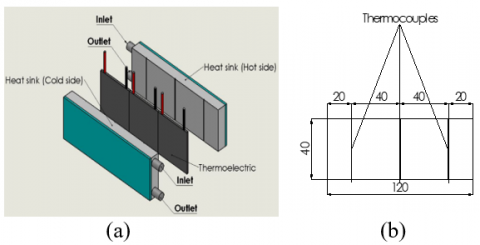
As shown in Figure 3, the Peltier cooling module consists of two water blocks and three Peltier plates. The present study tested the water heat sink with two different configurations (see Figure 4 for details). The optimized heat sink configuration was obtained from the numerical analysis using the CFD method, which is fabricated from the aluminum block. Two sides of three Peltier plates were attached with a water block using glue with high thermal conductivity to reduce interface thermal resistance. The details of the Peltier plates are listed in Table 1. The cold water obtained from the thermoelectric cooling module’s cold side was used for cooling the electric vehicle battery system in which the hot water replaces the generated heat from the cylindrical electric vehicle battery system with a constant temperature of 70℃. Type-T thermocouples were utilized to measure the hot and cold water inlet temperatures. An additional six thermocouples were used to measure the hot and cold surface temperatures of the Peltier plates (see Figure 3). The side surface temperatures of the Peltier plates were measured by machining the heat sink surface in a straight groove and then attaching three thermocouples to it. Acrylic and insulator sheets were used to insulate the TCM to decrease the energy loss during the experimental process. To repeat the experimental results, all parameters were measured and recorded five times using a Datataker DT85 and a personal computer.
Table 1. Details of thermoelectric plate
|
Details |
Ranges |
|
Voltage (V) |
12 |
|
Vmax (V) |
15.2 |
|
Imax (A) |
6 |
|
Qmax (W) |
92 |
|
DeltaTmax (℃) |
75 |
|
Internal (W) |
1.98±10% |
|
Size (mm*mm) |
40×40 |
Figure 3. Schematic diagram of (a) TCM (b) positions of installed thermocouples
Figure 4. Schematic diagram of heat sinks with different configurations (Water block)
2.4 Experimental procedure
Experiments were performed with different working fluid flow rates, supplied power input to the thermoelectric plate, and a pulsating flow frequency of coolant. For a given coolant flow rate and power provided to the thermoelectric plate, the nanofluids flowing through the thermoelectric module were increased in small increments. The experimental unit approached the steady-state condition before some relevant parameters were measured and recorded. All temperatures, pressure drop, supplied power to the Peltier plate, and working fluid flow rates were recorded five times. The working fluid flow rate was monitored and measured by flowmeters and the precise container was measured with a stopwatch, respectively. The collected fluid mass flowing in the system was measured using a digital weight scale (a 0.01% full-scale reading). A precision multi-meter was applied to measure and record the supplied current and voltage in the variation-controlled DC power supply (SP-Series: 60 V). The details of the experimental conditions are listed in Table 2. All data collection was performed using a data acquisition system. The pressure drop across the TCM was measured with the transducer (Yokakawa, MT120).
Table 2. Details of experimental conditions
|
Details |
Ranges |
|
Hot side flow rate of coolant (m3/hr) |
0.03-0.07 |
|
Cold side flow rate of coolant (m3/hr) |
0.03-0.07 |
|
Pulsating flow frequency (Hz) |
10, 15, 20 |
|
Supplied voltage (V) |
8, 10, 12 |
|
Nanofluids concentration (%vol.) |
0.005, 0.015 |
|
Constant temperature of cell electrical vehicle batteries (℃) |
70 |
2.5 Data reduction process
The input power given to the thermoelectric module, the heat removed by the nanofluids from the hot side channel, and water flowing through the cold side channel of the TCM was determined from the following equations;
$Q_{p}=I V$ (5)
$Q_{h, n f}=\dot{m}_{h, f f} C_{p, n f}\left(T_{h, \text { out }}-T_{h, i n}\right)_{n f}$ (6)
$Q_{\mathrm{c}, \mathrm{w}}=\dot{m}_{c, w} C_{p_{, w}}\left(T_{\mathrm{c}, \text { in }}-T_{\mathrm{c}, \text { out }}\right)_{w}$ (7)
The heat transfer coefficient and Nusselt number in the hot side channel of the TCM was determined from:
$h=\frac{Q_{h, n f}}{A_{s}\left(\Delta T_{L M T D}\right)}=\frac{\left(\rho A_{c r} U\right)_{n f} C_{p, n f}\left(T_{\text {out }, n f}-T_{\text {in }, n f}\right)}{A_{s}\left[\Delta T_{L M T D}=\frac{\left(T_{p}-T_{\text {out }, n f}\right)-\left(T_{p}-T_{\text {in }, n f}\right)}{\ln \left(\frac{\left(T_{p}-T_{\text {out }, n f}\right)}{\left(T_{p}-T_{\text {in }, n f}\right)}\right)}\right]}$ (8)
$\mathrm{Re}=\frac{\rho_{n f} U_{n f} D_{\text {inlet }}}{\mu_{n f}}$ (9)
The cold side and hot side coefficient of performance of the thermoelectric cooling module was calculated from:
$C O P_{c}=\frac{Q_{p}}{Q_{c, w}}=\frac{Q_{p}}{\dot{m}_{c, w} C_{p, w}\left(T_{c, \text { in }}-T_{c, \text { out }}\right)_{w}}$ (10)
$C O P_{h}=\frac{Q_{p}}{Q_{h, n f}}=\frac{Q_{p}}{\dot{m}_{h, f f} C_{p, n f}\left(T_{h, \text { out }}-T_{h, \text { in }}\right)_{n f}}$ (11)
where, Asis the surface area of the flow channel, $T_{i n, n f}$ , $T_{\text {out }, n f}$ are the temperatures at the inlet and outlet ports of the nanofluids, $\Delta T_{L M T D}$ is the logarithm mean temperature difference, $\dot{m}_{n f}$ is the coolant mass flow rate, $U_{n f}$ is the coolant velocity, h is the average heat transfer coefficient, $D_{\text {inlet }}$ is the diameter at the inlet port of the flow channel, DP is the pressure drop across the test section, $Q_{n f}$ is the heat transfer of the nanofluids, $T_{h p}$ is the hot side thermoelectric plate temperature, and Re is the Reynolds number.
2.6 Uncertainty analysis
Based on the uncertainties and accuracy (as shown in Table 3), the calculated maximum uncertainties [56] of the heat transfer coefficient and COP obtained from the calculation process are ±5.0%, ±5.0%, calculated from the following equations:
$\text { Uncertainty of } h=\sqrt{\left(\frac{\partial h}{\partial U} \Delta U\right)^{2}+\left(\frac{\partial h}{\partial T_{p}} \Delta T_{p}\right)^{2}+\left(\frac{\partial h}{\partial T_{\text {in }}} \Delta T_{\text {in }}\right)^{2}+\left(\frac{\partial h}{\partial T_{\text {out }}} \Delta T_{\text {out }}\right)^{2}}$ (12)
$\text { Uncertainty of } C O P=\sqrt{\left(\frac{\partial C O P}{\partial V} \Delta V\right)^{2}+\left(\frac{\partial C O P}{\partial I} \Delta I\right)^{2}+\left(\frac{\partial C O P}{\partial \dot{m}_{h}} \Delta \dot{m}_{h}\right)^{2}+\left(\frac{\partial C O P}{\partial T_{h, \text { out }}} \Delta T_{h, \text { out }}\right)^{2}+\left(\frac{\partial C O P}{\partial T_{h, \text { in }}} \Delta T_{h, \text { in }}\right)^{2}}$ (13)
Table 3. Accuracy and uncertainty of the instruments
|
Instruments |
Accuracy (%) |
Uncertainty |
|
Power supply, V |
0.2 |
±0.5 |
|
Type-T thermocouple |
0.1 |
±0.1 |
|
Pressure transducer |
0.02% |
±0.02 |
|
Data taker (oC) |
0.1 |
±0.1 |
|
Multi-meter |
0.1 |
±0.05 |
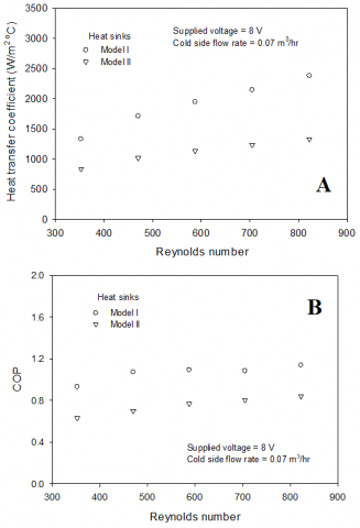
Based on the electric battery system review, it was found that most prior studies were numerically performed. The present analysis was done experimentally on the constant generated heat from the battery cell of 12.24 W (1860 type, 3.4A, 3.6V). For the generated heat that was less than 10W/cell, the battery cell surface temperature must be less than 40℃ and less than 70℃ for the generated heat 20-40W/cell [3]. The battery system’s liquid cooling module and the TCM’s water block were a newly designed configuration in the present study. Therefore, there are no previously published results with the same conditions for validation of the measured data. However, some papers presented the COP of the thermoelectric liquid chiller with similar conditions [57, 58]. In the present study, an electric vehicle battery’s generated heat was replaced by an electric heater, which kept a constant temperature of 70℃. Figure 5 shows the variations of (A) the hot side heat transfer coefficient and (B) the hot side COP of the TCM for different water block configurations. Two water blocks with different configurations, as shown in Figure 4, were tested for obtaining the highest thermal performance of the TCM. The hot side heat transfer coefficient and COP were determined from Eqns. (8) and (11), respectively. For a given supplied power input and cold side working fluid flow rate, a higher hot side coolant flow rate increases the heat transfer coefficient. This is because the removal cooling capability depends on the coolant flow rate. As seen in Figure 4, the coolant path lines in water block model I are wavy, while model II has straight lines, which gives a higher heat transfer rate. Therefore, the hot side heat transfer coefficient and COP obtained from the heat sink unit model I are higher than those from the heat sink unit model II. Based on the thermoelectric cooling module’s maximum thermal performance with water block model I, the effect of cold side coolant flow rate on the hot side heat transfer coefficient and hot side COP of the TCM is shown in Figure 6. As expected, the hot side’s removal capability depends on the coolant flow rates of the hot and cold sides. As the hot and cold coolant flow rates increase, so does the COP and heat transfer coefficient. We found that the present COP of the thermoelectric liquid cooling module was in the range of 0.5-1.2, while the COP obtained from Faraji et al. [57] and Liu et al. [58] were found to be in the range of 0.2–1.4, and 0.2-1.2, respectively.
Figure 7 shows the effect of input power on the thermoelectric plates on the hot side heat transfer coefficient and the hot side COP of the TCM. For a given hot side coolant Reynolds number of 830, the hot side heat transfer coefficient and COP of the thermoelectric cooling module was 2400 W/(m2 ℃) and 1.1 with an input voltage of 8V, respectively. By contrast, the hot aide heat transfer coefficient and COP of 2200 W/(m2 ℃) and 0.9 were obtained with an input voltage of 12 V. This means that higher input voltage to the Peltier plate increases the Joule heating and Fourier conduction effects which dominate over the Peltier effect. Therefore, the heat transfer coefficient and COP decrease as the input power increases.
Figure 5. Variations of (A) hot side heat transfer coefficient and (B) COP for different heat sinks
Figure 6. Variations of (A) hot side heat transfer coefficient and (B) COP for different cold side flow rates
Figure 7. Variations of (A) hot side heat transfer coefficient and (B) COP for different supplied voltages
Figure 8 shows the hot side heat transfer coefficient variations and COP of the thermoelectric cooling module for different pulsating hot side coolant flow frequencies. At cold and hot side working fluid flow rates of 0.03 m3/hr and 0.05 m3/hr, the experiment was conducted at various pulsating hot side flow frequencies. The pulsating flow frequency had a significant influence on the turbulent intensity of coolant by increasing removal capacity. Therefore, the pulsating flow frequency increases the heat transfer coefficient and COP of the TCM compared with using a continuous flow. Also, a higher pulsating flow frequency gives a higher mixing flow intensity, which increases the heat transfer coefficient and COP, as shown in Figure 8.
Figure 9 shows the effect of coolant types on the COP of the thermoelectric cooling module. Nanoparticles with an average diameter of 21 nm were used in an experiment in which nanoparticle suspension in the base fluid (water) influenced the nanofluid properties and the effect on turbulent intensity. Therefore, the coolant capability of nanofluid is greater than that of water; that is, the hot side heat transfer rate and COP of the thermoelectric cooling module were higher for nanofluids than for water. A larger heat transfer surface area and molecular collisions, higher nanofluid concentration yields an increase in cooling capability and COP. However, this also slightly increases the pressure drop across the test section. The thermal physical properties tend to increase due to nanoparticles being suspended in the base fluid when compared to water. Nevertheless, different nanofluid concentrations, like those used in the present experiment, have slightly different influences on the pressure drop increases (see Figure 10).
Figure 8. Effect of pulsating flow frequency on (A) heat transfer coefficient and (B) COP
Figure 9. Variations of heat transfer rate and COP for different coolants
Figure 10. Variations of pressure drop for different coolants at supplied voltage=10V and cold side flow rate=0.03 m3/hr
Due to higher power density and heat generation inside the modern electric vehicle battery system, choosing cooling solutions for these devices significantly affects the maintenance of their operating temperature. The water/nanofluids pulsating flow results in the thermoelectric module for cooling electric vehicle battery systems were presented. We found that the designed heat sink model I (water block) yields a higher heat transfer coefficient and COP compared to model II. The coolant two side flow rates, power input, and coolant types have a significant influence on the thermoelectric cooling module’s thermal performance. The thermoelectric module yields around 2.5-3.5℃ lower inlet temperatures before entering the electric vehicle battery system relative to those without a thermoelectric module. The proposed water block model from this study was used to optimize the battery thermal management system for obtaining higher performance.
The authors would like to express their appreciation to the Srinakharinwirot University (SWU) for providing financial support for this study.
|
ATEG |
automotive thermoelectric generator |
|
|
AC/DC |
alternatiing current/direct current, A |
|
|
BTMS |
battery thermal management system |
|
|
TCM |
thermoelectric cooloing module |
|
|
$C_{p}$ |
specific heat, kJ. kg-1. ℃-1 |
|
|
COP |
coefficient of performance |
|
|
D |
diameter, m |
|
|
k |
thermal conductivity, kW. m-1. ℃-1 |
|
|
mnf |
nanofluids mass flow rate, kg. s-1 |
|
|
Pr |
Prandtl number |
|
|
Q |
heat transfer rate, kW |
|
|
Re |
Reynolds number |
|
|
T |
temperature, ℃ |
|
|
TAC |
thermoelectric active cooling |
|
|
TCM |
thermoelectric cooling module |
|
|
TSC |
thermoelectric self-cooing |
|
|
U |
velocity, m. s-1 |
|
|
Greek symbols |
|
|
|
$\phi$ |
nanofluids concentration, % |
|
|
$\rho$ |
density, kg. m-3 |
|
|
$\mu$ |
viscosity, kg. m-1. s-1 |
|
|
Subscripts |
|
|
|
ave |
average |
|
|
in |
inlet |
|
|
nf |
nanofluids |
|
|
p |
particles |
|
|
out |
outlet |
|
[1] Gould, C.A., Shammas, N.Y.A, Grainger, S., Taylor, I. (2011). Thermoelectric cooling of microelectronic circuits and waste heat electrical power generation in a desktop personal computer. Materials Science and Engineering B, 176(4): 316-325. https://doi.org/10.1016/j.mseb.2010.09.010
[2] Martínez, A., Astrain, D., Rodríguez, A. (2011). Experimental and analytical study on thermoelectric self-cooling of devices. Energy, 36(8): 5250-5260. https://doi.org/10.1016/j.energy.2011.06.029
[3] Kinsella, C.E., O’Shaughnessy, S.M., Deasy, M.J., Duffy, M., Robinson, A.J. (2014). Battery charging considerations in small scale electricity generation from a thermoelectric module. Applied Energy, 114: 80-90. https://doi.org/10.1016/j.apenergy.2013.09.025
[4] Suh, I.S., Cho, H., Lee, M. (2014). Feasibility study on thermoelectric device to energy storage system of an electric vehicle. Energy, 76: 436-444. https://doi.org/10.1016/j.energy.2014.08.040
[5] Huang, B.J., Hsu, P.C., Tsai, R.J., Hussain, M.M. (2015). A thermoelectric generator using loop heat pipe and design match for maximum-power generation. Applied Thermal Engineering, 91: 1082-1091. https://doi.org/10.1016/j.applthermaleng.2015.08.059
[6] Borisyuk, P.V., Krasavin, A.V., Tkalya E.V., Lebedinskii, Y.Y., Vasiliev, O.S., Yakovlev, V.P., Kozlova, T.I., Fetisov, V.V. (2016). Nanocluster metal films as thermoelectric material for radioisotope mini battery unit. Chemical Physics, 478: 2-7. https://doi.org/10.1016/j.chemphys.2016.07.010
[7] Kiflemariam, R., Lin, C.X. (2016). Experimental investigation on heat driven self-cooling application based on thermoelectric system. International Journal of Thermal Sciences, 109: 309-322. https://doi.org/10.1016/j.ijthermalsci.2016.06.001
[8] Zhang, C., Li, K., Deng, J. (2016). Real-time estimation of battery internal temperature based on a simplified thermoelectric model. Journal of Power Sources, 302: 146-154. https://doi.org/10.1016/j.jpowsour.2015.10.052
[9] Atouei, S.A., Ranjbar, A.A., Rezania, A. (2017). Experimental investigation of two-stage thermoelectric generator system integrated with phase change materials. Applied Energy, 208: 332-343. https://doi.org/10.1016/j.apenergy.2017.10.032
[10] Liu, K., Li, K., Zhang, C. (2017). Constrained generalized predictive control of battery charging process based on a coupled thermoelectric model. Journal of Power Sources, 347: 145-158. https://doi.org/10.1016/j.jpowsour.2017.02.039
[11] Rao, Z., Qian, Z., Kuang, Y., Li, Y. (2017). Thermal performance of liquid cooling based thermal management system for cylindrical lithium-ion battery module with variable contact surface. Applied Thermal Engineering, 123: 1514-1522. https://doi.org/10.1016/j.applthermaleng.2017.06.059
[12] Chen, K., Wang, S., Song, M., Chen, L. (2017). Configuration optimization of battery pack in parallel air-cooled battery thermal management system using an optimization strategy. Applied Thermal Engineering, 123: 177-186. https://doi.org/10.1016/j.applthermaleng.2017.05.060
[13] Chen, K., Wang, S., Song, M., Chen, L. (2017). Structure optimization of parallel air-cooled battery thermal management system. International Journal of Heat and Mass Transfer, 111: 943-952. https://doi.org/10.1016/j.ijheatmasstransfer.2017.04.026
[14] Chen, K., Song, M., Wei, W., Wang, S. (2018). Structure optimization of parallel air-cooled battery thermal management system with U-type flow for cooling efficiency improvement. Energy, 145: 603-613. https://doi.org/10.1016/j.energy.2017.12.110
[15] Chen, K., Hong, S., Zhang, X., Wang, S. (2018). Design of flow configuration for parallel air-cooled battery thermal management system with secondary vent. International Journal of Heat and Mass Transfer, 116: 1204-1212. https://doi.org/10.1016/j.ijheatmasstransfer.2017.09.092
[16] Chen, K., Chen Y., Li, Z., Yuan, F., Wang, S. (2018). Design of the cell spacings of battery pack in parallel air-cooled battery thermal management system. International Journal of Heat and Mass Transfer, 127: 393-401. https://doi.org/10.1016/j.ijheatmasstransfer.2018.06.131
[17] Lu, Z., Yu, X., Wei, L., Qiu, Y., Zhang, L., Meng, X., Jin, L. (2018). Parametric study of forced air cooling strategy for lithium-ion battery pack with staggered arrangement. Applied Thermal Engineering, 136: 28-40. https://doi.org/10.1016/j.applthermaleng.2018.02.080
[18] Zhao, C., Cao, W., Dong, T., Jiang, F. (2018). Thermal behavior study of discharging/charging cylindrical lithium-ion battery module cooled by channeled liquid flow. International Journal of Heat and Mass Transfer, 120: 751-762. https://doi.org/10.1016/j.ijheatmasstransfer.2017.12.083
[19] Arora, S. (2018). Selection of thermal management system for modular battery packs of electric vehicles: A review of existing and emerging technologies. Journal of Power Sources, 400: 621-640. https://doi.org/10.1016/j.jpowsour.2018.08.020
[20] Cao, Q., Luan, W., Wang, T. (2018). Performance enhancement of heat pipes assisted thermoelectric generator for automobile exhaust heat recovery. Applied Thermal Engineering, 130: 1472-1479. https://doi.org/10.1016/j.applthermaleng.2017.09.134
[21] Daghigh, R., Khaledian, Y. (2018). Effective design, theoretical and experimental assessment of a solar thermoelectric cooling-heating system. Solar Energy, 162: 561-572. https://doi.org/10.1016/j.solener.2018.01.012
[22] Ebrahimi, M., Derakhshan, E. (2018). Design and evaluation of a micro combined cooling, heating, and power system based on polymer exchange membrane fuel cell and thermoelectric cooler. Energy Conversion and Management, 171: 507-517. https://doi.org/10.1016/j.enconman.2018.06.007
[23] Li, X., Xie, C., Quan, S., Huang, L., Fang, W. (2018). Energy management strategy of thermoelectric generation for localized air conditioners in commercial vehicles based on 48 V electrical system. Applied Energy, 231: 887-900. https://doi.org/10.1016/j.apenergy.2018.09.162
[24] Muralidhar, N., Himabindu, M., Ravikrishna, R.V. (2018). Modeling of a hybrid electric heavy duty vehicle to assess energy recovery using a thermoelectric generator. Energy, 148: 1046-1059. https://doi.org/10.1016/j.energy.2018.02.023
[25] Song, W., Bai, F., Chen, M., Lin, S., Feng, Z., Li, Y. (2018). Thermal management of standby battery for outdoor base station based on the semiconductor thermoelectric device and phase change materials. Applied Thermal Engineering, 137: 203-217. https://doi.org/10.1016/j.applthermaleng.2018.03.072
[26] Wang, C., Niu, Y., Jiang, J., Chen, Y., Tian, H., Zhang, R., Zhou, T., Xia, J., Pan, Y., Wang, S. (2018). Hybrid thermoelectric battery electrode FeS2 study. Nano Energy, 45: 432-438. https://doi.org/10.1016/j.nanoen.2018.01.025
[27] Abedi, H., Migliorini, F., Dondè, R., De Iuliis, S., Passaretti, F., Fanciulli, C. (2019). Small size thermoelectric power supply for battery backup. Energy, 188: 116061. https://doi.org/10.1016/j.energy.2019.116061
[28] Cai, Y., Wang, W.W., Ding, W.T., Yang, G.B., Liu, D., Zhao, F.Y. (2019). Entropy generation minimization of thermoelectric systems applied for electronic cooling: Parametric investigations and operation optimization. Energy Conversion and Management, 186: 401-414. https://doi.org/10.1016/j.enconman.2019.02.064
[29] Comamala, M., Massaguer, A., Massaguer, E., Pujol, T. (2019). Validation of a fuel economy prediction method based on thermoelectric energy recovery for mid-size vehicles. Applied Thermal Engineering, 153: 768-778. https://doi.org/10.1016/j.applthermaleng.2019.03.004
[30] Dan, D., Yao, C., Zhang, Y., Zhang, H., Zeng, Z., Xu, X. (2019). Dynamic thermal behavior of micro heat pipe array-air cooling battery thermal management system based on thermal network model. Applied Thermal Engineering, 162: 114183. https://doi.org/10.1016/j.applthermaleng.2019.114183
[31] Darcovich, K., MacNeil, D.D., Recoskie, S., Cadic, Q., Ilinca, F. (2019). Comparison of cooling plate configurations for automotive battery pack thermal management. Applied Thermal Engineering, 155: 185-195. https://doi.org/10.1016/j.applthermaleng.2019.03.146
[32] Dufo-López, R., Champier, D., Gibout, S., Lujano-Rojas, J.M., Domínguez-Navarro, J.A. (2019). Optimisation of off-grid hybrid renewable systems with thermoelectric generator. Energy Conversion and Management, 196: 1051-1067. https://doi.org/10.1016/j.enconman.2019.06.057
[33] Fotso, B.E.M., Talawo, R.C., Feudjio, N.M.C., Fogue, M. (2019). Modeling and thermal analysis of a solar thermoelectric generator with vortex tube for hybrid vehicle. Case Studies in Thermal Engineering, 15: 100515. https://doi.org/10.1016/j.csite.2019.100515
[34] Jiang, L., Zhang, H., Li, J., Xia, P. (2019). Thermal performance of a cylindrical battery module impregnated with PCM composite based on thermoelectric cooling. Energy, 188: 116048. https://doi.org/10.1016/j.energy.2019.116048
[35] Kwan, T.H., Shen, Y., Yao, Q. (2019). An energy management strategy for supplying combined heat and power by the fuel cell thermoelectric hybrid system. Applied Energy, 251: 113318. https://doi.org/10.1016/j.apenergy.2019.113318
[36] Lan, S., Smith, A., Stobart, R., Chen, R. (2019). Feasibility study on a vehicular thermoelectric generator for both waste heat recovery and engine oil warm-up. Applied Energy, 242: 273-284 https://doi.org/10.1016/j.apenergy.2019.03.056
[37] Lyu, Y., Siddique, A.R.M., Majid, S.H., Biglarbegian, M., Gadsden, S.A., Mahmud, S. (2019). Electric vehicle battery thermal management system with thermoelectric cooling. Energy Reports, 5: 822-827. https://doi.org/10.1016/j.egyr.2019.06.016
[38] Massaguer, E., Massaguer, A., Pujol, T., Comamala, M., Montoro, L., Gonzalez, J.R. (2019). Fuel economy analysis under a WLTP cycle on a mid-size vehicle equipped with a thermoelectric energy recovery system. Energy, 179: 306-314. https://doi.org/10.1016/j.energy.2019.05.004
[39] Sulaiman, M.S., Singh, B., Mohamed, W.A.N.W. (2019). Experimental and theoretical study of thermoelectric generator waste heat recovery model for an ultra-low temperature PEM fuel cell powered vehicle. Energy, 179: 628-646. https://doi.org/10.1016/j.energy.2019.05.022
[40] Shiriaev, P., Shishov, K. Osipkov, A. (2019). Electrical network of the automotive multi-sectional thermoelectric generator with MPPT based device usage. Materials Today: Proceedings, 8(Part 2): 642-651. https://doi.org/10.1016/j.matpr.2019.02.064
[41] Toan, N.V., Hasnan, M.M.I.M., Udagawa, D., Inomata, N., Toda, M., Said, S.M., Sabri, M.F.M., Ono, T. (2019). Thermoelectric power battery using al2o3 nanochannels of 10 nm diameter for energy harvesting of low-grade waste heat. Energy Conversion and Management, 199: 111979. https://doi.org/10.1016/j.enconman.2019.111979
[42] Naphon, P., Sriromruln, P. (2006). Single-phase heat transfer and pressure drop in the micro-fin tubes with coiled wire insert. Int. Comm. in Heat and Mass Transfer, 33(2): 176-183. https://doi.org/10.1016/j.icheatmasstransfer.2005.08.012
[43] Naphon, P., Sookkasem, A. (2007). Investigation on heat transfer characteristics of tapered cylinder pin fin heat sinks. Energy Conversion and Management, 48(10): 2671-2679. https://doi.org/10.1016/j.enconman.2007.04.020
[44] Naphon, P., Kornkumjayrit, K. (2008). Numerical analysis on the fluid flow and heat transfer in the channel with V-shaped wavy lower plate. International Communications in Heat and Mass Transfer, 35(7): 839-843. https://doi.org/10.1016/j.icheatmasstransfer.2008.03.010
[45] Naphon, P., Wongwises, S., Wiriyasart, S. (2013). Application of two-phase vapor chamber technique for hard disk drive cooling of PCs. Int. Comm. in Heat and Mass Transfer, 40: 32-35. https://doi.org/10.1016/j.icheatmasstransfer.2012.10.014
[46] Abbas, N., Awan, M.W., Amer, M., Ammar, S.M., Sajjad, U., Ali, H.M., Zahra, N., Hussain, M., Badshah, M.A., Jafry, A.T. (2019). Applications of nanofluids in photovoltaic thermal systems: A review of recent advances. Physica A: Statistical Mechanics and its Applications, 536: 122513. https://doi.org/10.1016/j.physa.2019.122513
[47] Javed, S., Ali, H.M., Babar, H., Khan, M.S., Janjua, M.M., Bashir, M.A. (2020). Internal convective heat transfer of nanofluids in different flow regimes: A comprehensive review. Physica A: Statistical Mechanics and its Applications, 538: 122783. https://doi.org/10.1016/j.physa.2019.122783
[48] Abbas, F., Ali, H.M., Shah, T.R., Babar, H., Janjua, M.M., Sajjad, U., Amer, M. (2020). Nanofluid: Potential evaluation in automotive radiator. Journal of Molecular Liquids, 297: 112014. https://doi.org/10.1016/j.molliq.2019.112014
[49] Ali, H.M. (2020). In tube convection heat transfer enhancement: SiO2 aqua based nanofluids. Journal of Molecular Liquids, 308: 113031. https://doi.org/10.1016/j.molliq.2020.113031
[50] Ambreen, T., Saleem, A., Ali, H.M., Shehzad, S.A., Park, C.W. (2019). Performance analysis of hybrid nanofluid in a heat sink equipped with sharp and streamlined micro pin-fins. Powder Technology, 355: 552-563. https://doi.org/10.1016/j.powtec.2019.07.087
[51] Babar H., Ali, H.M. (2019). Airfoil shaped pin-fin heat sink: Potential evaluation of ferric oxide and titania nanofluids. Energy Conversion and Management, 202: 112194. https://doi.org/10.1016/j.enconman.2019.112194
[52] Pak, B.C., Cho, Y.I. (1998). Hydrodynamic and heat transfer study of dispersed fluids with submicron metallic oxide particles. Experiment Heat Transfer, 11(2): 151-170. https://doi.org/10.1080/08916159808946559
[53] Xuan, Y., Roetzel, A. (2000). Conceptions of heat transfer correlation of nanofluids. International Journal of Heat and Mass Transfer, 43(19): 3701-3707. https://doi.org/10.1016/S0017-9310(99)00369-5
[54] Drew, D.A., Passman, S.L. (1999). Theory of Multicomponent Fluids. Springer, Berlin.
[55] Maxwell, J.C. (1881). A Treatise on Electricity and Magnetism. Second ed. Clarendon Press, Oxford University, UK.
[56] Coleman, H.W., Steele, W.G. (1989). Experimental and Uncertainty Analysis for Engineers. John Wiley&Sons, New York.
[57] Faraji, A.Y., Goldsmid, H.J., Akbarzadeh, A. (2014). Experimental study of a thermoelectrically-driven liquid chiller in terms of COP and cooling down period. Energy Conversion and Management, 77: 340-348. https://doi.org/10.1016/j.enconman.2013.09.047
[58] Liu, Y., Su, Y. (2018). Experimental investigations on COPs of thermoelectric module frosting systems with various hot side cooling methods. Applied Thermal Engineering, 144: 747-756. https://doi.org/10.1016/j.applthermaleng.2018.08.056