Ning Cai* | Dongliang Zhang
© 2021 IIETA. This article is published by IIETA and is licensed under the CC BY 4.0 license (http://creativecommons.org/licenses/by/4.0/).
OPEN ACCESS
In this paper, an experimental study on radiant floor cooling integrated with underfloor ventilation (RFCUV) system was conducted. Indoor environment temperatures, radiant floor cooling system parameters and underfloor ventilation system parameters were measured. Humane thermal comfort was analyzed experimentally. And the effects of disturbance variables and manipulated variables on controlled variables were analyzed. The results illustrated that operative temperature (OT), predicted mean vote (PMV) and predicted percent dissatisfied (PPD) decrease in the first two hours and then become stable in ISO7730 recommended value range. IAT and OT increase with the increasing of the disturbance variables and manipulated variables. The increasing ratio of indoor air temperature (IAT) and OT are relatively small when comprehensive outdoor air temperature is relatively high and indoor heat quantity or average water temperature is relatively low. IAT and OT increase approximately linearly with the increasing of supply air temperature.
radiant floor cooling, underfloor ventilation, operating characteristic
In radiant floor cooling integrated with underfloor ventilation (RFCUV) system, both convective heat transfer and radiant heat transfer play an important role in RFCUV system. In radiant floor cooling system, heat transfer area of floor surface is considerable, so chilled water with high temperature is available for the system. Therefore, various low-grade cooling sources, such as groundwater, cooling tower water, and chilled water from ground heat exchanger, etc. are able to be supplied to radiant cooling system. To avoid radiant floor surface condensation, cooling water temperature should be lower than room air dew point temperature. Thus, underfloor ventilation system is introduced for dehumidification to guarantee occupant thermal comfort. In recent years, the use of RFCUV system in buildings has been increased [1, 2]. Because of above characteristics, there has been a growing interest on RFCUV system.
Up to now, there have been several studies dealing with RFCUV system in literature. Studies are mainly focused on cooling load calculation methods [3, 4], cooling capacity estimation [5, 6], energy consumption comparison [7-9] and thermal comfort assessment [10, 11], etc. Feng et al. [3, 4] analyzed cooling load differences between radiant and air systems and conducted experimental comparison of zone cooling load between radiant and air systems. Zhang et al. [5] proposed simplified calculation method for cooling/heating capacity and surface temperature distribution of radiant floor. Odyjas and Górka [6] simulated cooling capacity of floor cooling system. Energy consumption of radiant floor cooling combined with dehumidifying ventilation system was compared to that of conventional air conditioning system during cooling period [7, 8]. And it was found that the former accounts for only 1/3 of the latter. A comparison of the energy consumption estimates shows that savings of 80% is possible in case thermal comfort is achieved through radiant cooling instead of conventional air-conditioning [9]. Simos analyzed thermal comfort performance of radiant cooling system [10]. Tian and Love [11] revealed that thermal comfort model of radiant cooling system is consistent with PMV model, and discomfort caused by vertical temperature gradient and blowing is effectively improved in radiant cooling system by analyzing thermal comfort of 82 subjects in radiant cooling system. Compared thermal comfort of radiant floor cooling system and radiant ceiling cooling system were compared by Conceição and Lúcio [12] under the same condition by numerical simulation, and found that thermal comfort of radiant floor cooling system is better.
Currently, seldom researches have been conducted on humane thermal comfort and the effects of disturbance and input on output of RFCUV system, which will be analyzed experimentally in this paper. This study is the basis for operation optimization and control strategy of RFCUV system, which is of necessity and significance.
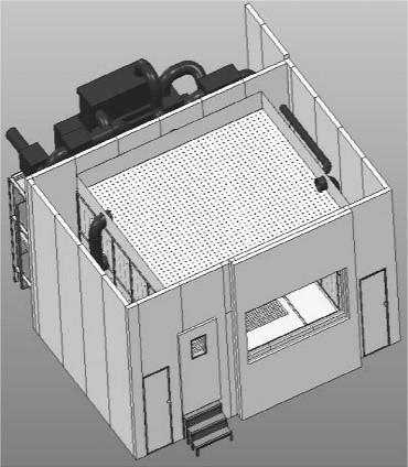
In this paper, experimental study is conducted for humane thermal comfort analysis and the effects of disturbance variables and manipulated variables on controlled variables. The size of the test room is 4.2 m´3.6 m´2.6 m. The lab sketch (a room equipped with RFCUV system) is presented in Figure 1. Thermal property parameters of radiant floor construction, building envelope, and surfaces are presented in Table 1. Outside the test room, there is a compensate room. All-air system is used to handle air to support the environment of compensate room that the experiments require. The pipe spacing is 100 mm and the pipe diameter is 10 mm. Total pipe length is 142 m. Water flow rate is 0.024 kg/s in pipes. Chilled water is provided by air source heat pump and then distributed by manifold to every water loop. In the experiment, temperature of inlet water, outlet water, outdoor air, indoor air, building envelope interior surfaces and water flow rate are measured. Testing instruments and its parameters are presented in Table 2.
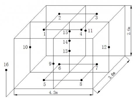
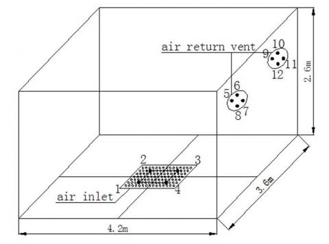
As presented in Figure 2, average temperature of four points on the ceiling or floor represents ceiling or floor surface temperature. Average temperature of points 13, 14, 15 represents indoor air temperature. The heights of point 13, 14, 15 from the ground are 1.1 m, 1.7 m and 2.2 m, respectively. Point 13 represents the position of breathing when sitting. Point 14 represents the position of breathing when standing. And point 15 represents the position of top when standing. These test points temperature are measured per 30 min due to large thermal inertia of RFCUV system. As presented in Figure 3, 12 velocity test points are laid to measure air velocity of inlet and outlet. Average velocity of four test points of inlet or outlet represents air velocity of inlet or outlet.
Figure 1. Lab sketch
Table 1. Parameters of RFCUV system
|
Floor construction |
Thickness (mm) |
Thermal conductivity (W/(m K)) |
Building envelope |
Heat transfer coefficient (W/(m2 K)) |
Surface |
Coefficient |
|
Floor slab layer |
100 |
1.0 |
Exterior door |
3.0 |
Inner surfaces emission |
0.89 |
|
Pipe |
1 |
380 |
Exterior window |
2.8 |
Exterior surfaces absorption |
0.73 |
|
Pipe layer |
22 |
– |
Exterior wall |
1.0 |
– |
– |
|
Surface layer |
12 |
0.41 |
Exterior surfaces |
18.2 |
– |
– |
Table 2. Testing instruments and parameters
|
Testing parameters |
Surface temperature |
Air temperature and humidity |
Air velocity |
Water flow |
Water temperature |
|
|
Testing instruments |
Infrared thermometer |
Psychrometer |
Heat bulb anemometer |
Ultrasonic flowmeter |
Thermometer |
|
|
Measuring range |
-32-535℃ |
-20-60℃ |
10%-95% |
0-20 m/s |
0-±32m/s |
0-100℃ |
|
Measuring precision |
±1℃ |
±0.8℃ |
±3% |
<5% |
±1% |
- |
Figure 2. Temperature test points distribution sketch
Figure 3. Air velocity test points distribution sketch
3.1 Analysis of PMV and PPD
According to IS07730, Predicted Mean Vote (PMV) and Predicted Percent Dissatisfied (PPD) are two indexes for thermal comfort evaluation. The two indexes are proposed by Fanger who gathered 1396 American and Denmark examines’ reflection on cold and hot feeling. Because cold and heat are subjective feelings, PMV value can only represent the feelings of most people under the same conditions. Therefore, PPD index is used to express the dissatisfaction percentage, and the relationship between them is given with the method of probability and statistics. When PMV=0, PPD=5%. In other words, in the most comfortable state, 5% of people are still dissatisfied.
The basic basis of PMV-PPD method is the heat balance equation of human body below:
$M-W-C-R-E=S$ (1)
where, M is the heat production of metabolism, W; W is the work done by the human body, W; C is convective heat dissipation, W; R is the radiation and heat dissipation between human body and surrounding environment, W; E is evaporation heat dissipation, W; S human body heat storage, W.
The recommended range of PMV and PPD in ISO7730 are as follows: −0.5≤PMV≤+0.5, PPD≤10%.
In RFCUV system, radiant heat-transfer between interior room surface and humane body is one factor that affect humane thermal comfort. Thus, besides PMV and PPD, operating temperature (OT) is proposed to evaluate thermal comfort.
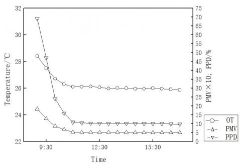
The calculated results are shown in Figure 4. OT, PMV and PPD decrease in the first two hours and then become stable. After two hours, both PMV and PPD value are in ISO7730 recommended value range.
Compared with the traditional air conditioner, the composite system increases the radiation heat exchange between the human body and the surrounding. Some data show that in the total heat dissipation of the human body, convection heat dissipation accounts for 30%, radiation heat dissipation accounts for 45%, evaporation heat dissipation accounts for 25%. Under the floor radiation, the total heat dissipation of the human body increases by 10%, and the radiation heat dissipation is 2.23 times that of non-radiation cooling. It can be explained that under the condition of radiant cooling, air temperature is not a single standard for evaluating indoor thermal comfort, and mean radiant temperature (MRT) and operation temperature (OT) will be more accurate for evaluating indoor comfort.
Figure 4. Thermal comfort indexes calculation
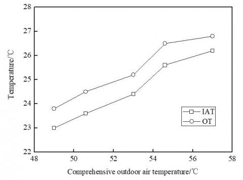
In RFCUV system, comprehensive outdoor air temperature and indoor heat quantity are two main disturbance variables. Variations of indoor air temperature (IAT) and operative temperature (OT) with comprehensive outdoor air temperature are shown in Figure 5. The results illustrate that IAT and OT increase with the increasing of comprehensive outdoor air temperature, and the increasing ratios are relatively small when comprehensive outdoor air temperature is relatively high.
The operative temperature (OT) takes into account the comprehensive action of the average radiation temperature and indoor air, and can be calculated by the following formula:
$O T=\frac{h_{r} \bar{t}_{r}+h_{c} t_{a}}{h_{r}+h_{c}}$ (2)
where, OT is operative temperature, ℃, hr is Radiant heat transfer coefficient, w/(m2∙k), hc is Convective heat transfer coefficient, w/(m2∙k).
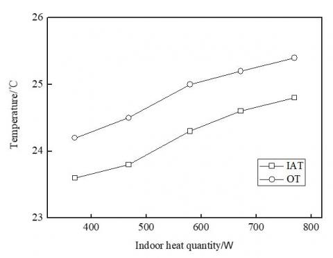
Variations of IAT and OT with indoor heat quantity are presented in Figure 6. The results indicate that IAT and OT increase with the increasing of indoor heat quantity, and the increase ratio of IAT and OT is relatively small when indoor heat quantity is relatively low.
Figure 5. Variations of IAT and OT with comprehensive outdoor air temperature
Figure 6. Variations of IAT and OT with indoor heat quantity
In RFCUV system, average water temperature and supply air temperature are two main manipulated variables. The effects of the above two main manipulated variables on controlled variables are studied in the following. Variations of IAT and OT with average water temperature are presented in Figure 7. The results illustrated that IAT and OT increase with the increasing of average water temperature, and the increase ratio of IAT and OT is relatively small when average water temperature is relatively low.
Figure 7. Variations of IAT and OT with average water temperature
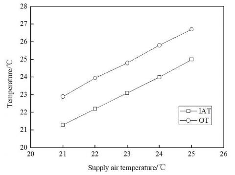
The effect of supply air temperature on IAT and OT are presented in Figure 8. The results show that, under the stable condition, IAT and OT increase approximately linearly with the increase of supply air temperature.
Figure 8. Variations of IAT and OT with supply air temperature
3.2 Analysis of MRT
The average radiation temperature (MRT) can be defined as: assuming that in a closed space composed of an insulated blackbody surface, the radiation heat exchange between the human body and the surrounding is the same as that in an actual room, the average surface temperature of the blackbody closed space is the average radiation temperature of the actual room. For this system, the average radiation temperature includes the average radiation temperature of the floor environment and the average radiation temperature of the human body environment. The former refers to the average radiation temperature of other surfaces except the floor to the floor, and the latter refers to the average radiation temperature of all surfaces of the room to the human body in the room. There are two calculation methods for the average radiation temperature, one is calculated according to the definition, and the other is area weighted according to the average temperature of the inner surface of the envelope. It and can be calculated by the following formula:
$\overline{t_{r}}=\frac{\sum A_{i} t_{i}}{\sum A_{i}}$ (3)
where, $\overline{t_{r}}$ is MRT, ℃, Ai is the i surface area, m2, ti is the i surface temperature, ℃。
Take the stable state of radiation heat transfer: 12-38 hours. The average radiation temperature at each time is as follows (Table 3):
Table 3. Change of MRT with time
|
Time |
12 |
13 |
14 |
15 |
16 |
17 |
18 |
19 |
20 |
21 |
22 |
23 |
24 |
|
Method one |
30.64 |
30.21 |
30.52 |
30.54 |
30.17 |
30.19 |
30.24 |
29.71 |
29.45 |
29.71 |
29.46 |
29.54 |
29.59 |
|
Method two |
31.23 |
30.84 |
31.12 |
31.15 |
30.80 |
30.83 |
30.85 |
30.40 |
30.18 |
30.47 |
30.17 |
30.26 |
30.35 |
|
25 |
26 |
27 |
28 |
29 |
30 |
31 |
32 |
33 |
34 |
35 |
36 |
37 |
38 |
|
29.46 |
29.97 |
29.53 |
30.01 |
30.14 |
29.77 |
29.76 |
29.63 |
29.77 |
29.89 |
29.73 |
29.23 |
29.86 |
29.46 |
|
30.14 |
30.70 |
30.27 |
30.67 |
30.82 |
30.39 |
30.48 |
30.38 |
30.45 |
30.47 |
30.42 |
29.92 |
30.50 |
30.16 |
According to the calculation of method 1, the lowest average radiation temperature of the floor environment is 29.46 ℃, the highest is 30.86 ℃, and the average is 29.9 ℃. According to the calculation of method 2, the lowest average radiation temperature of the floor environment is 29.82 ℃, the highest is 31.43 ℃, and the average is 30.57 ℃. It can be seen that the average radiation temperature calculated by area weighting is slightly higher, but it can be ignored in the process of engineering design.
3.3 Analysis of cooling capacity
The cooling capacity of the system is also composed of two parts: radiant heat transfer (Qr) from the floor to the surrounding surface and human body and air convection heat transfer (Qc) caused by displacement ventilation.
$Q_{t a l}=Q_{r}+Q_{c}$ (4)
$Q_{r}=\varepsilon_{f} \sigma T_{f}^{4}-\sum_{i=1}^{n} \varepsilon_{i} \sigma T_{i}^{4} F_{f-i}$ (5)
where: εf is the emissivity of the floor; σ is Stephen Boltzmann constant, w/m2K4; Tf is the floor temperature, ℃, εi is the emissivity of other surfaces; Ti is the surface temperature of other enclosure structures except the floor, ℃; Ff-i is the angle coefficient of the floor to the second surface.
$Q_{r}=h_{r} \sum_{i=1}^{n}\left(T_{f}-T_{i}\right) F_{f-i}$ (6)
where, hr is the radiant heat transfer coefficient, W/(m2∙k).
$h_{r}=\varepsilon_{f} \sigma \theta$ (7)
$\theta=\frac{T_{f}^{4}-T_{i}^{4}}{T_{f}-T_{i}}$ (8)
The convective heat transfer can be calculated by the following formula:
$Q_{c}=h_{c}\left(I A T-t_{f}\right)$ (9)
where, hc is the Convective heat transfer coefficient, W/(m2∙k),
The total heat transfer resistance is:
$h_{t o l}=h_{r}+h_{c}$ (10)
Dr. Olesen pointed out that for people sitting and standing, the heat transfer coefficient between the floor and the room is generally about 1.23Btu/ft2/hr/◦F (7W/m2 ℃), Where 0.97BTU/ft2/HR/F (5.5W/m2 ℃) is radiation heat transfer; Considering the comfort limit of the maximum operating temperature of 79F (26.1℃) for the sedentary personnel, the maximum cooling capacity of the floor radiation system is 16btu/HR/ft2 (50W/ m2) [13].
According to the above calculation method, select the stable time and calculate the heat transfer coefficient and heat transfer, as shown in the Table 4 below.
Table 4. Variation of heat transfer parameters with time
|
Time |
Qtol/W |
tf/℃ |
MRT/℃ |
htol/W/m2℃ |
|
12 |
49.63 |
22.50 |
30.64 |
5.80 |
|
13 |
47.40 |
22.42 |
30.21 |
5.79 |
|
14 |
48.88 |
22.50 |
30.52 |
5.80 |
|
15 |
47.03 |
22.83 |
30.54 |
5.81 |
|
16 |
48.12 |
22.25 |
30.17 |
5.78 |
|
17 |
47.70 |
22.35 |
30.19 |
5.78 |
|
18 |
49.09 |
22.17 |
30.24 |
5.78 |
|
19 |
50.05 |
21.42 |
29.71 |
5.74 |
|
20 |
47.97 |
21.50 |
29.45 |
5.74 |
|
21 |
46.69 |
22.00 |
29.71 |
5.76 |
|
22 |
48.04 |
21.50 |
29.46 |
5.74 |
|
23 |
49.49 |
21.33 |
29.54 |
5.74 |
|
24 |
49.78 |
21.33 |
29.59 |
5.74 |
|
25 |
50.43 |
21.08 |
29.46 |
5.73 |
|
26 |
54.14 |
21.00 |
29.97 |
5.74 |
|
27 |
49.43 |
21.33 |
29.53 |
5.74 |
|
28 |
49.53 |
21.83 |
30.01 |
5.76 |
|
29 |
49.40 |
22.00 |
30.14 |
5.77 |
|
30 |
47.06 |
22.00 |
29.77 |
5.76 |
|
31 |
51.35 |
21.25 |
29.76 |
5.74 |
|
32 |
50.06 |
21.33 |
29.63 |
5.74 |
|
33 |
50.92 |
21.33 |
29.77 |
5.74 |
|
34 |
48.32 |
21.92 |
29.89 |
5.76 |
|
35 |
49.72 |
21.50 |
29.73 |
5.75 |
|
36 |
49.96 |
20.92 |
29.23 |
5.72 |
|
37 |
50.07 |
21.58 |
29.86 |
5.75 |
|
38 |
47.55 |
21.58 |
29.46 |
5.74 |
It can be seen from the calculated data that when the system operates stably, the radiant heat transfer coefficient can basically remain stable, and is basically consistent with the comprehensive heat transfer coefficient proposed by Dr. Olsen, which is 5.5W/m2 ℃. In the experiment, the average radiant heat transfer coefficient is 5.74 W / m2 ℃.
Overall, the radiant heat transfer is basically stable in the whole process. Even when the floor temperature and indoor air temperature rise after shutdown, the radiant heat transfer of the floor can remain stable. Here, the heat storage performance of the enclosure is the main reason.
The convective heat transfer caused by air supply includes: the convective heat transfer between air supply and floor, and the convective heat transfer between indoor air and the inner surface of enclosure structure. Comparing the changes of the floor temperature and the inner surface temperature of the enclosure in the first and third experiments, it can be seen that under the operation of the composite system, the floor temperature and the inner surface temperature of the enclosure decrease to a certain extent, and the decrease degree of the inner surface temperature of the enclosure is higher than that of the floor, Thus, the temperature difference between the floor temperature and the average radiation temperature of other envelope structures is reduced, and the total amount of radiation heat transfer of the floor is reduced. It can be proved that the introduction of air supply reduces the radiation heat transfer between the floor and the enclosure, and the lower the air supply temperature, the higher the air supply speed and the smaller the radiation heat transfer.
According to the method above, the Equivalent radiant heat transfer coefficient is 5.68 W/m2 ℃, the Natural convection heat transfer coefficient is 9.48 W/m2 ℃.
The comprehensive equivalent heat transfer coefficient of floor (hcef) combines the comprehensive effects of average radiation temperature and indoor air temperature. According to method above, the hcef is 28.17 W/m2 ℃.
The research on the operation mode of air conditioning system is basically considered from two aspects: to produce a comfortable indoor environment and meet the requirements of energy conservation and consumption reduction.
The control of the system includes the control of water system and air system. It can be divided into different types according to different control parameters. For the control system, the control parameters can be divided into input variables, such as air temperature, action temperature, outdoor air temperature, floor temperature, indoor air humidity, etc; Control variables, such as air temperature and action temperature; Execute variables such as water temperature, water flow.
For the control of water system, it is generally divided according to the executive variables, including water flow and water temperature control. There are two control modes of water volume, one is to control the flow by starting and stopping, and the other is variable flow control. The former control system is relatively simple, and the latter can minimize the energy consumption of the pump, but the control system is more complex. There are generally two kinds of water temperature control: one is outdoor temperature open-loop control, which sets the water temperature control line according to the outdoor temperature. This method is not sensitive to the change of indoor temperature; one is outdoor temperature combined with indoor temperature compensation control.
The air system is basically controlled by starting and stopping the fan, and the start and stop of the air system are adjusted according to the changes of indoor air dew point temperature and floor temperature.
The economic evaluation of the system includes: initial investment (equipment and raw material purchase cost, equipment installation and commissioning cost, civil engineering and labor cost), operation and maintenance investment (operation energy consumption, equipment maintenance and repair cost).
In terms of equipment, due to the introduction of action temperature, the design and selection capacity of the unit is reduced. At the same time, the heat storage of the enclosure and the selection of intermittent operation mode also greatly reduce the size and capacity of the refrigeration device. Since the water system bears most of the indoor load, the air system can be designed and selected with the minimum air volume, and the energy consumption of air transmission will be greatly reduced.
In this paper, an experimental study on operating characteristic of RFCUV system has been conducted. Based on the experimental results analysis, the following conclusions are obtained.
(1) OT, PMV and PPD decrease in the first two hours and then become stable in ISO7730 recommended value range.
(2) IAT and OT increase with the increasing of comprehensive outdoor air temperature, and the increasing ratios are relatively small when comprehensive outdoor air temperature is relatively high.
(3) The increasing ratio of IAT and OT are relatively small when comprehensive outdoor air temperature is relatively high and indoor heat quantity or average water temperature is relatively low.
(4) In this case, IAT and OT increase approximately linearly with the increasing of supply air temperature.
(5) Through analysis and calculation, in the most unfavorable outdoor environment during the operation of the composite system, when the ground temperature is maintained at about 21℃, the air supply temperature is 21℃ and the air supply wind speed is 1m / s, the equivalent comprehensive heat transfer coefficient of the floor to the action temperature is 13.6w/m2 ℃, in which the equivalent radiant heat transfer coefficient is 5.68w/m2 ℃ and the convective heat transfer coefficient is 9.48w/m2 ℃, and the higher the air supply speed The lower the air supply temperature, the lower the radiant heat transfer of the floor.
The authors gratefully acknowledge the support provided by the Talent International Exchange and Training Program 2019 and scientific research fund of Nanjing Institute of Technology under grant no. CKJA201803.
[1] Mumma, S.A. (2001). Overview of integrating dedicated outdoor air systems with parallel terminal systems/discussion. ASHRAE Transactions, 107: 545.
[2] Hu, R., Niu, J.L. (2012). A review of the application of radiant cooling & heating systems in Mainland China. Energy and Buildings, 52: 11-19. https://doi.org/10.1016/j.enbuild.2012.05.030
[3] Feng, J.D., Schiavon, S., Bauman, F. (2013). Cooling load differences between radiant and air systems. Energy and Buildings, 65: 310-321. https://doi.org/10.1016/j.enbuild.2013.06.009
[4] Feng, J.D., Bauman, F., Schiavon, S. (2014). Experimental comparison of zone cooling load between radiant and air systems. Energy and Buildings, 84: 152-159. https://doi.org/10.1016/j.enbuild.2014.07.080
[5] Zhang, L., Liu, X.H., Jiang, Y. (2012). Simplified calculation for cooling/heating capacity, surface temperature distribution of radiant floor. Energy and Buildings, 55: 397-404. https://doi.org/10.1016/j.enbuild.2012.08.026
[6] Odyjas, A., Górka, A. (2013). Simulations of floor cooling system capacity. Applied Thermal Engineering, 51(1-2): 84-90. https://doi.org/10.1016/j.applthermaleng.2012.08.029
[7] Leigh, S.B., Song, D.S., Hwang, S.H., Lee, S.Y. (2005). A study for evaluating performance of radiant floor cooling integrated with controlled ventilation. ASHRAE Transactions, 111: 71-82.
[8] Song, D., Kim, T., Song, S., Hwang, S., Leigh, S.B. (2008). Performance evaluation of a radiant floor cooling system integrated with dehumidified ventilation. Applied Thermal Engineering, 28(11-12): 1299-1311. https://doi.org/10.1016/j.applthermaleng.2007.10.020
[9] Memon, R.A., Chirarattananon, S., Vangtook, P. (2008). Thermal comfort assessment and application of radiant cooling: A case study. Building and Environment, 43(7): 1185-1196. https://doi.org/10.1016/j.buildenv.2006.04.025
[10] Oxizidis, S., Papadopoulos, A.M. (2013). Performance of radiant cooling surfaces with respect to energy consumption and thermal comfort. Energy and Buildings, 57: 199-209. https://doi.org/10.1016/j.enbuild.2012.10.047
[11] Tian, Z., Love, J.A. (2008). A field study of occupant thermal comfort and thermal environments with radiant slab cooling. Building and Environment, 43(10): 1658-1670. https://doi.org/10.1016/j.buildenv.2007.10.012
[12] Conceição, E.Z., Lúcio, M.M.J. (2011). Evaluation of thermal comfort conditions in a classroom equipped with radiant cooling systems and subjected to uniform convective environment. Applied Mathematical Modelling, 35(3): 1292-1305. https://doi.org/10.1016/j.apm.2010.09.006
[13] Olesen, B.W. (1997). Possibilities and limitations of radiant floor cooling (No. CONF-9702141-). American Society of Heating, Refrigerating and Air-Conditioning Engineers, Inc., Atlanta, GA (United States).