Itimad D.J. Azzawi* | Samir Gh Yahya | Layth Abed Hasnawi Al-Rubaye | Senaa Kh. Ali
© 2021 IIETA. This article is published by IIETA and is licensed under the CC BY 4.0 license (http://creativecommons.org/licenses/by/4.0/).
OPEN ACCESS
In this study, natural convection of heat transfer in various channel geometries with a constant surface area under laminar flow condition has been investigated numerically. Various hot surface temperatures (Th = 35-95°C) have been applied on the surfaces of the channels to investigate four different geometries of annular channels (Circular (C), Square (S), Elliptic (E) and Airfoil (F)) on the heat transfer rate. Once the optimum geometry was exhibited, the effect of three nanofluids (Al2O3/water, CuO/water and SiO2/water) is investigated in the analysis and compared to pure water to enhance the convective heat transfer of the base fluid. Moreover, with these nanofluids, analysis has been performed for three different volume concentrations of nanoparticles of Ø = 2%, 4% and 6% along with 0% (pure water). Porous foams (ε = 0.9 to 0.99) were used in addition to nanofluids to see if heat transfer could be improved. Results indicate that the heat transfer rate was greatly increased when the airfoil geometry was used, with a maximum and minimum increase in heat transfer coefficient of 60% and 46%, respectively. Also, higher nanoparticle of Al2O3 dispersion to the base fluid enhances the heat transfer rate by 15% compared to other nanofluids.
natural convection, aerofoil configuration, nanofluid, porous media
The design of heat transfer devices to exchange heat between two or more fluids is one of the most widely used applications of heat transferring [1-4]. Many researchers have been focused on applying natural convection in a variety of industrial applications including heat exchangers, furnaces, solar collectors, electrical part cooling, and so on. The character of these studies can be categorized as experimental [5], theoretical [6], or numerical [7-9]. In the later studies, the enclosures can be various configurations including rectangular or cubical [10-12], cylindrical [13], spherical [14], or in the shape of cylindrical annulus [15] and the solutions can be steady [16] or unsteady condition [12, 13, 17]. Moreover, natural convection heat transfer was conducted to investigate the heat transfer rate between a hot triangular cylinder and its circular cylindrical enclosure using numerical simulation [18]. The angles of inclination of the inner triangular cylinder were discovered to have little impact on the average Nusselt number. Also, the heat transfer rate between a square outer cylinder and a circular inner cylinder in a horizontal eccentric annulus was investigated using the differential quadrature process [19]. Furthermore, numerical simulation was used to study the natural convection and heat transfer rate using five different geometries of an inner cylinder mounted in a circular enclosure. The findings revealed that the local heat transfer rate at the solid surface has a slight geometrical effect [20]. Natural convection from elliptical and circular cylinders has recently gotten a lot of attention because of their improved heat transfer properties without a lot of pressure drop [21-24].
However, in addition the geometrical parameters, several parameters were examined by many researchers to enhance the heat transfer rate and these parameters include pipes material, working fluid and porous media. Nanofluids are anemometric particle dispersions (typically less than 100 nm in diameter), called nanoparticles, in a base fluid in order to improve certain properties [25-28]. The first fluid dispersed by nanoparticles was prepared by Choi and Eastman in 1995 [25]. A number of authors have done experimental and theoretical research on improving heat-transfer with nanofluids [26-31] and their results have shown that the heat-transfer rate of nanofluids is higher than that of base fluids (pure water). Much is being done about the Al2O3 nanofluid, which is being investigated experimentally by Kim et al. [32] on the effect of the nanofluid on the heat-transfer through a circular tube using Al2O3 nanoparticles in a turbulent regime. The use of Al2O3/water nanoparticles was shown to increase the n heat-transfer rate. The rate of improvement was 15% and 20%. In a 3D elliptic annular passage, Dawood et al. [33] performed a computational analysis of natural convection heat transfer flow for various forms of nanofluids (Al2O3–water, CuO–water, SiO2-water, and ZnO–water). They reported that the heat transfer rate of SiO2–water nanofluid is the highest, followed by Al2O3–water, ZnO–water, CuO–water, and pure water, in that order. Another three various nanofluids (Al2O3-water, CuO-water, and Cu-water) was used to enhance the heat transfer in a square cross section duct using numerical simulation [34]. Cu-water, CuO-water, and Al2O3-water nanofluids had Nusselt number improvements of 77%, 68%, and 59%, respectively at volume of fraction of 4%. The pressure drop was also investigated by Yin et al. [35] using Cu-water nanofluid flow in a pipe both experimentally and numerically, measuring pressure drop. The findings revealed that nanofluids with a volumetric nanoparticle concentration of less than 2.5% improved heat transfer with less pressure drop.
Based on the literature reviewed, for specific engineering applications, designing an annular heat channel is not straightforward since both the operating fluid and geometrical specifications used should be considered. Therefore, the present research focusing on three main parts. Initially, four various geometries of annular channels (Circular (C), Square (S), Elliptic (E) and Airfoil (F)) were investigated in terms of heat flux (q), heat transfer coefficient (h) and pressure drop (p) against surface hot temperature using pure water. Two further numerical investigations are carried out after the optimal configuration in terms of desired heat transfer rate has been defined. A computational investigation of heat transfer rate and pressure drop using three various nanofluids (Al2O3/water, CuO/water and SiO2/water) with different volume fractions (Ø = 2%, 4% and 6% along with 0% (pure water)) was compared to pure water to increase the thermal conductivity of the chosen annular channel. Finally, to see if incorporating porous media with varying porosities (saturated metal foam with porosities of ε=0.9, 0.95, and 0.99) improves natural convection heat transfer.
2.1 Problem description
The concentric annular pipe of four different configurations is adopted in the current study, as shown in Figure 1, which have the same contact area of 0.005 m2 for all cases. Four distinct geometric inner walls are set with four different hot temperatures Th, while the outer walls are set with a constant cold temperature Tc. With the first letter of each geometry set, these arrangements are called such that the letters C= Circular, S= Square, E= Ellipse and A= Airfoil. In addition, once the optimal configuration in terms of thermal performance was obtained, three different types of nanofluids named Al2O3, CuO and SiO2 were also compared to pure water to investigate the effect of these nanofluids on the thermal performance. Three different fraction volumes of Ø = 2%, 4% and 6% along with 0% (pure water) are also investigated with these nanofluids. Finally, the effect of saturated porous media (saturated metal foam with porosity of ε =0.9, 0.95 and 0,99) on the natural convection heat transfer within the optimum configuration was determined. Moreover, With the exception of density, which varies according to the Boussinesq approximation, the thermophysical properties of the nanofluid are assumed to be constant. Table 1 summarizes these properties of the various forms of nanoparticles and the base fluid used for code validation.
Figure 1. Different geometries of concentric annular pipe; C: circle, E: ellipse, S: square, A: airfoil
Table 1. Base fluid (Water) and nanoparticles thermophysical properties used in the current study
|
ρ (kg/m3) |
Cp(J/kg.K) |
K(W/m.K) |
β (1/K) |
|
|
Pure water |
997 |
4180 |
0.607 |
$2.47 \times 10^{-4}$ |
|
Aluminum oxide (Al2O3) |
3600 |
765 |
36 |
$5.8 \times 10^{-6}$ |
|
Copper Oxide (CuO) |
6500 |
533 |
17.65 |
$4.3 \times 10^{-6}$ |
|
Silicon dioxide (SiO2) |
2220 |
745 |
1.4 |
$5.5 \times 10^{-6}$ |
2.2 Assumptions and natural convection heat transfer model
In this analysis, the flow is assumed to be steady state, laminar and incompressible with single phase nanofluid model is employed by assuming that the base fluid (pure water) and (Al2O3, CuO and SiO2) nanoparticles are in thermal equilibrium and no slip between them occurs. In addition, the Boussinesq approximations are valid study and two‐dimensional natural convection flow in all four different geometries was applied to maintain the hydraulic thermal characteristics of working fluid. The Aluminum foam is rigid, isotropic, homogeneous and fully saturated with liquid. Local-Thermal-Equilibrium (LTE) applies between solid and liquid in everywhere (T = Ts = Tf). Also considering Darcy-Brinkman- Forchheimer equation for flow inside the porous foam. In view of these assumptions, the model problem can be described by the conservation of mass, momentum under Boussinesq approximation, and energy. The partial differential equations based on the previous assumptions will be formulated as [36]:
For the nanofluid:
Continuity equation:
$\frac{\partial u}{\partial x}+\frac{\partial v}{\partial y}=0$ (1)
x-momentum equation:
$\rho_{n f}\left(u \frac{\partial u}{\partial x}+v \frac{\partial u}{\partial y}\right)=-\frac{\partial p}{\partial x}+\mu_{n f}\left(\frac{\partial^{2} u}{\partial x^{2}}+\frac{\partial^{2} u}{\partial y^{2}}\right)$ (2)
y-momentum equation:
$\rho_{n f}\left(u \frac{\partial v}{\partial x}+v \frac{\partial v}{\partial y}\right)=-\frac{\partial p}{\partial y}+\mu_{n f}\left(\frac{\partial^{2} v}{\partial x^{2}}+\frac{\partial^{2} v}{\partial y^{2}}\right)+(\rho \beta)_{n f} g\left(T-T_{c}\right)$ (3)
Energy equation:
$u \frac{\partial T}{\partial x}+v \frac{\partial T}{\partial y}=\frac{k_{n f}}{(\rho c)_{n f}}\left(\frac{\partial^{2} T}{\partial x^{2}}+\frac{\partial^{2} T}{\partial y^{2}}\right)$ (4)
For the porous media:
Continuity equation:
$\frac{\partial u}{\partial x}+\frac{\partial v}{\partial y}=0$ (5)
x-momentum equation:
$\rho_{n f}\left(\frac{1}{\varepsilon^{2}} \frac{\partial u}{\partial x}+\frac{v}{\varepsilon^{2}} \frac{\partial u}{\partial y}\right)=-\frac{\partial p}{\partial x}+\frac{\mu_{n f}}{\varepsilon}\left(\frac{\partial^{2} u}{\partial x^{2}}+\frac{\partial^{2} u}{\partial y^{2}}\right)-\frac{\mu_{n f}}{K} u$ (6)
y-momentum equation:
$\rho_{n f}\left(\frac{u}{\varepsilon^{2}} \frac{\partial v}{\partial x}+\frac{v}{\varepsilon^{2}} \frac{\partial v}{\partial y}\right)=-\frac{\partial p}{\partial y}+\frac{\mu_{n f}}{\varepsilon}\left(\frac{\partial^{2} v}{\partial x^{2}}+\frac{\partial^{2} v}{\partial y^{2}}\right)-(\rho \beta)_{n f} g\left(T-T_{c}\right)-\frac{\mu_{n f}}{K} v$ (7)
Energy equation:
$(\rho c)_{n f}\left(\frac{\partial T_{n f}}{\partial x}+v \frac{\partial T_{n f}}{\partial y}\right)=\varepsilon k_{n f}\left(\frac{\partial^{2} T_{n f}}{\partial x^{2}}+\frac{\partial^{2} T_{n f}}{\partial y^{2}}\right)+h\left(T_{s}-T_{n f}\right)$ (8)
$(1-\varepsilon) k_{s}\left(\frac{\partial^{2} T_{s}}{\partial x^{2}}+\frac{\partial^{2} T_{s}}{\partial y^{2}}\right)+h\left(T_{n f}-T_{s}\right)+q$ (9)
The coefficient of average heat transfer (h) and average Nusselt number (Nu) are calculated by the following relations:
$h=\frac{q}{\left(T_{h}-T_{c}\right)}$ (10)
$N_{u}=\frac{h L_{c}}{k_{f}}$ (11)
The effective density (ρnf), heat capacitance (ρCp)nf, thermal conductivity (Knf) and dynamic viscosity (μnf) for the three different nanofluids that are applied in this study, such as Al2O3-H2O, CuO-H2O and SiO2-H2O are presented by the following equations [34]:
$\rho_{n f}=(1-\emptyset) \rho_{f}+\emptyset \rho_{n p}$ (12)
$\left(\rho C_{P}\right)_{n f}=(1-\emptyset)\left(\rho C_{p}\right)_{f}+\emptyset\left(\rho C_{P}\right)_{n p}$ (13)
$k_{n f}=k_{\text {Static }}+k_{\text {Browain }}$ (14)
$k_{\text {Static }}=k_{f}\left(\frac{\left(k_{n p}+2 k_{f}\right)-2 \emptyset\left(k_{f}-k_{n p}\right)}{\left(k_{n p}+2 k_{f}\right)+\emptyset\left(k_{f}-k_{n p}\right)}\right)$ (15)
$k_{\text {Browinan }}=5 \times 10^{4} \beta \emptyset \rho_{f} C_{p f} \sqrt{\frac{k_{b} T}{\rho_{p} d_{p}}} f(T, \emptyset)$ (16)
$f(T, \emptyset)=\left(2.8217 \times 10^{-2} \emptyset+3.917 \times 10^{-3}\right)\left(\frac{T}{T_{0}}\right)+\left(-3.0669 \times 10^{-2} \emptyset-3.91123 \times 10^{-3}\right)$ (17)
$\frac{\mu_{n f}}{\mu_{f}}=\frac{1}{1-34.87\left(\frac{d_{n p}}{d_{f}}\right)^{-0.3} \emptyset^{1.03}}$ (18)
The particle diameter of nanofluids (dp) is taken 20 nm and the nanofluid is supposed a suspension and homogeneous in the base fluid (pure water).
2.3 Computational implementation and boundary conditions
The computational domain of concentric annular horizontal pipe and grid creation is handled by Ansys Fluent-CFD. The dominated equations were solved using a computational fluid dynamics (CFD) program with the boundary conditions and assumptions added. This package has been used to solve heat transfer equations and laminar fluid flow using finite volume method (FVM) [35]. For the pressure-velocity coupling, the SIMPLE algorithm is applied to the convective term of the second order upwind technique. To approximate the energy, momentum, and continuity equations, this second order upwind is applied in the diffusion term. The simulation is convergent when the residual sum for momentum, continuity and energy equations was less than 10-6.
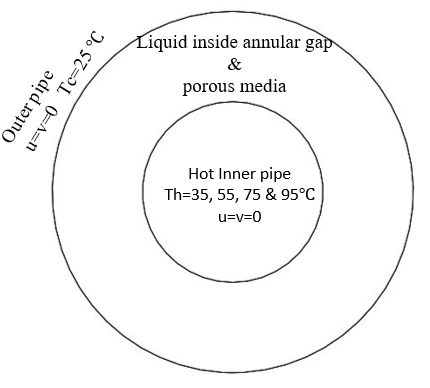
A hot temperature range Th = (35-95)℃ was applied along the inner diameter of the inner pipe, as seen in Figure 2, whereas the outer surface of the outer pipe is held at Tc = 25℃. The place between the two pipes is filled with the specified liquid (pure water or nanofluids) at several of volume fraction (Ø = 0, 2%, 4% and 6%) and the wall boundary conditions are assumed to be no‐slip condition in two x-y directions (u = v = zero).
Figure 2. Boundary conditions of a concentric annular pipe
2.4 Model validation and mesh sensitivity
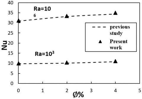
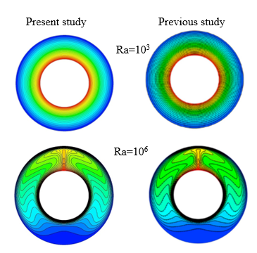
Figures 3 and 4 show the validation between the average Nusselt number and isotherms of Gholamalipour et al. [37] and the current numerical study data is conducted using nanofluid for elliptic at two Rayleigh numbers of 103 and 106 as shown in Figure 3. The streamline of isotherms is simulated in an elliptical annular pipe filled with porous media using pure water and the effects are then compared also with the work carried out by Gholamalipour et al. [37] as seen in Figure 4. Figure 4 clearly showed that at a porosity of ε = 0.9, there is a good agreement found in terms of streamline isotherms at both Rayleigh numbers. Additionally, the average Nusselt number of the current numerical simulation were also compared with data obtained by Gholamalipour et al. [37] at a porosity of ε=0.9 as shown in Figure 3. The figure clearly revealed that the overall difference between the current study and previous research is 2.9% at the Rayleigh number of 103, whereas the maximum discrepancy at the Rayleigh number of 106 was 1.4%. Overall, by considering the results of the two above studies, the numerical solution method of the present analysis is validated with enough accuracy.
Figure 3. The average Nu values of the present work are compared with results of previous study at zero eccentricity (ξ = 0) [37]
Figure 4. Validation isotherms contour of previous study of Gholamalipoura et al. [37] (Right) and present CFD study (Left) at ε = 0.9
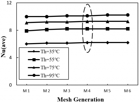
To save the computational time and memory for the present numerical analysis, various numbers of grids are used to create different mesh distributions to approve their mesh independence. Six various mesh sizes were generated ranged between M1 = 9x10³ to M6 = 30x103 element number as shown in Figures 5 and 6. In terms of the monitoring variable of Nusselt number (Nu) at various hot temperature using pure water, Figure 5 shows the results for assessing mesh sensitivity on a circular annular pipe. Based on the results, M4=22x103 was considered to be the optimal element for numerical solutions since the percentage of error beyond this number of elements is less than 1% for the Nusselt number. The number of M4 cells was therefore chosen for all cases used in the current research at various configurations in order to use the computational time effectively without losing the accuracy of the computation.
Figure 5. Mesh sensitivity for annular circle pipe using pure water
Figure 6. Computational grid domain for six mesh sizes
3.1 Different annular geometry effect
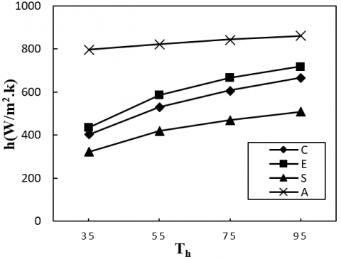
In the present analysis, the natural convection between a constant cold outer surface (Tc = 25℃) and various applied hot temperatures (Th = 35℃ – 95℃) of the inner surface (Th) is studied numerically in four different geometries, circle (C), ellipse (E), square (S) and airfoil (A) using pure water. The effect of these hot temperatures on the heat transfer coefficient (h), heat flux (q) and pressure drop (p) is shown in Figures 7-9. The variations in the coefficient of heat transfer with respect to four geometries and different hot temperatures are clearly shown in Figure 7. It can be found that heat transfer coefficient almost increases linearly with the increase in Th, and however, when the airfoil channel shape is applied, heat transfer rate was higher than that in other three shapes. For instance, compared to the other three channel configurations (circle (C), ellipse (E), square (S)), the airfoil channel at Th= 35℃ has twice heat transfer coefficient. In general, compared to airfoil pipe, square (S), circle (C), ellipse (E) have 60%, 50% and 46% lower heat transfer coefficient, respectively due to that airfoil channel has no sharp angles and hence higher heat transfer rate. It is also worth noting that the effect of hot surface temperature in the heat transfer enhancement becomes more significant at low hot temperature.
Figure 7. Heat transfer coefficient against hot surface temperature for different concentric annular shapes using pure water
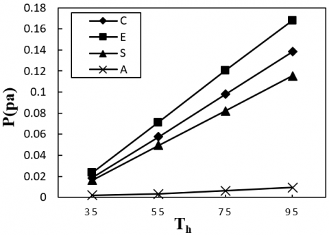
Figure 8. Pressure drop inside against hot surface temperature for different concentric annular shapes using pure water
Figure 9. Heat flux against hot surface temperature for different concentric annular shapes using pure water
The pressure drop at different channel configurations is seen in Figure 8 as a function of hot surface temperature. Similarly, the increase in the hot surface temperature would increase the pressure drop and however, a significant reduction in the pressure drop can be seen when airfoil channel has been used. In accordance with our expectation, when the airfoil channel was used, due to the reduction of secondary flow, the heat transfer rate increases, and the pressure drop decreases. In comparison, Figure 9 clearly showed how the heat flux also increased when the airfoil channel was used due to the curved profile as more aerodynamic geometries can be seen in Figure 9. In addition, from these figures mentioned above, it can be understood that the hot surface temperature within the elliptic and circular channels is about 2% lower than other geometries relative to the triangle channel. To conclude, airfoil cross-sectional channel had a significant pressure drop reduction and highest Nusselt number compared other cross-sectional channels, so airfoil cross-sectional channel is more efficient than others.
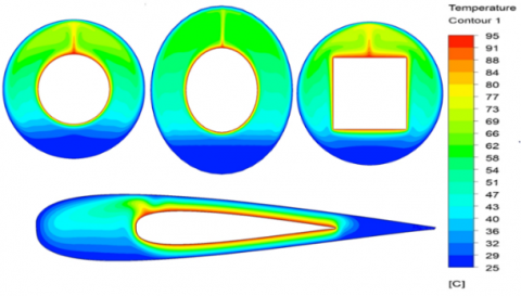
Figure 10. Temperature distribution for different (circle, ellipse, square and airfoil) and various Th= 95℃
Figure 11. Velocity distribution for different (circle, ellipse, square and airfoil) and various Th= 95℃
Figure 12. Pressure distribution for different shape (circle, ellipse, square and airfoil) and various Th= 95℃
Figures 10-12 show the pressure, velocity, and temperature distribution contours of cross-sectioned Circular (C), Square (S), Elliptic (E) and Airfoil (F) at Th = 95℃ for the inner surface. Temperature contours show thermally developing flow, while velocity contours show hydrodynamically developing flow as contours move from inlet to outlet portions. As a result of the no-slip condition, the flow near the edges slows down, and a greater temperature gradient occurs near the edges and this phenomenon causes Nusselt number to decrease. However, the highest temperature is achieved with square cross-sectioned channel geometry for the same flow conditions, and the lowest temperature is reached with elliptical cross-sectioned channel geometry. As shown in Figure 12, elliptical channel geometry generates the least pressure drop, while non-circular channel geometry generates the most pressure drop in square geometry due to higher wall temperatures at their edges.
3.2 Nanofluids and volume of fraction effect
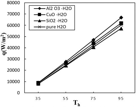
Based on the above results, the airfoil shape was shown to have the best thermal performance compared to the other three geometries. Therefore, variation of heat transfer coefficient, heat flux and pressure drop related to three different nanofluids as a function of hot surface temperature with constant volume fraction of 2% were examined and compared to pure water for airfoil configuration. It was observed from Figure 13 that the Al2O3-H2O nanofluid gives the largest heat transfer coefficient compared to other types of nanofluids since the configuration of the Al2O3-H2O nanofluid with airfoil pipe shape gives the highest fluid mixing and thermal conductivity and thus increases the heat transfer area greater than other types of nanofluids which agreed with results showed by Ting and Hou [31] and Heris et al. [34]. Based on the results shown in Figures 13-15, Al2O3 nanoparticles suspended in base water shows a higher heat transfer coefficient, heat flux and pressure drop than pure water, CuO-H2O and SiO2-H2O nanofluids. Figure 14 clearly show that as the hot temperature increased, the heat flux also increased for all nanofluids used. It can be concluded that the heat transfer coefficient for Al2O3-H2O nanofluid was thus increased by 8%, 10% and 15% compared to the other three nanofluids; SiO2-H2O, pure water and CuO-H2O, respectively. However, greater heat transfer coefficient means greater thermal performance despite the pressure drop increase as shown in Figure 15. Moreover, the heat transfer coefficient of the airfoil cross-sectional channel using CuO-H2O nanofluid is higher than SiO2-H2O nanofluid and pure water with very low pressure drop.
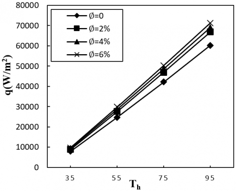
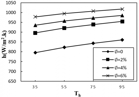
Analyses have been also performed for Al2O3-H2O nanofluid that gives the best thermal performance for volume fraction of nanoparticles ranged between 2% and 6% in airfoil cross-sectioned channel at various hot inner wall temperatures. Figure 16 shows how the heat flux increase as the hot temperature increase for the all nanoparticle concentrations. Moreover, the heat transfer coefficient of the Al2O3-H2O nanofluid with different volumetric nanoparticle concentrations enhanced the heat transfer rate and as the concentration increased, the thermal performance also increased. Obtained enhancement of the heat transfer coefficient for 0% (pure water), 2%, 4% and 6% volume of fractions were 11.7%, 23.8%, 26.1% and 28.5% respectively (see Figure 17) and similar behavior was seen by Abareshi et al. [38] which indicates a good mixing can be produced at higher volume of fraction. Furthermore, the results showed that greater nanoparticle concentrations mean higher thermal conductivity and hence greater pressure drop despite the heat transfer performance increase as shown in Figure 18. Therefore, lower pressure drop can be seen when the pure water was applied such that as the nanoparticles are inserted, the pressure drop increased with increase of the hot surface temperature.
Figure 13. Heat transfer coefficient against hot surface temperature for airfoil channel at different coolant nanofluids
Figure 14. Heat flux against hot surface temperature for airfoil channel at different coolant nanofluids
Figure 15. Pressure drop against hot surface temperature for airfoil channel at different coolant nanofluids
Figure 16. Heat flux against hot surface temperature for airfoil at different volume fraction of Al2O3-H2O
Figure 17. Heat transfer coefficient against hot surface temperature for airfoil at different volume fraction of Al2O3-H2O
Figure 18. Pressure drop against hot surface temperature for airfoil at different volume fraction of Al2O3-H2O
Figure 19. Heat flux against different applied Th at various porosity amount $\varepsilon=0.9,0.95$ and $0.99$
Figure 20. Heat transfer coefficient against different applied Th at various porosity amount ε = 0.9, 0.95 and 0.99
Figure 21. Pressure coefficient against different applied Th at various porosity amount ε = 0.9, 0.95 and 0.99
3.3 Porous media amount effect
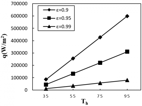
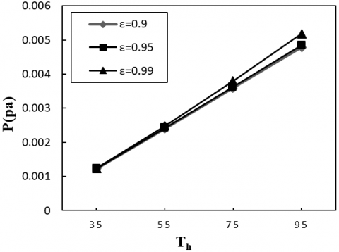
Once the optimum geometry, nanofluid and volume of fraction (Al2O3-H2O at volume fraction of 6%) in terms of the desirable heat transfer rate were established, the effect of porous media in term at various porosities (ε= 0.9, 0.95 and 0.99) is investigated as shown in Figures 19-21. In addition, in order to improve the hydraulic-thermal properties of the airfoil channel chosen, the desired responses were determined on the basis of heat flux, heat transfer coefficient and pressure drop. As shown in Figures 19-20, as the porosity (ε) values increased from 0.9 to 0.99, heat flux and the heat transfer coefficient and hence heat transfer rate decreased. This is because a large surface area contact can be achieved with the lowest porosity values, and thus a lower heat transfer rate can be reported. The optimal operating conditions for porosity in terms of delivering a maximum thermal efficiency (h) were therefore calculated at the lowest values of ε = 0.9 with a reasonable improvement in the pressure drop in the specified range as shown in Figure 21. Furthermore, the pressure drop shows different behaviour such that the pressure drop is almost constant for all porous amounts. However, to conclude, from Figures 19-21, it has been found that the maximum heat transfer enhancement has been obtained by reaching minimum porosity for any value of hot surface temperature.
A numerical investigation of various nanofluids, varying volumes of fraction flowing within different channel geometries, exposed to a uniform and different hot surface temperatures boundary condition, was successfully carried out in this study using a single-phase approach. The results showed that for the same hot surface temperature, elliptical cross-sectioned channel geometry offers up to twice compared to other type of geometries such that compared to airfoil pipe, square (S), circle (C), ellipse (E) have 60%, 50% and 46% lower heat transfer coefficient, respectively. Moreover, Nanoparticle of Al2O3 dispersion to the base fluid enhances the heat transfer rate by 15%. Regarding to the fraction volumes, higher volumetric nanoparticle concentration of nanofluids have higher heat transfer rate with low pressure drop. In addition to using nanoparticles, porous foams (ε = 0.9 to 0.99) were implemented to investigate whether the heat transfer can be enhanced. The results showed that heat flux and the heat transfer coefficient and hence heat transfer rate increased as the porosity decrease. This is because a large surface area contact can be achieved with the lowest porosity values, and thus a higher heat transfer rate can be reported.
|
Da |
Darcy number |
|
Dp |
The particle diameter of nanofluids, m |
|
G |
gravitational acceleration, m.s2 |
|
H |
heat transfer coefficient, W m-3 K-1 |
|
K |
thermal conductivity, W.m-1. K-1 |
|
Nu |
local Nusselt number along the heat source |
|
Q |
heat flux, W. m2 |
|
Ra |
Rayleigh number |
|
T |
Temperature. K |
|
u,v |
velocity components, m.s-1 |
|
x,y |
Cartesian coordinates |
|
Greek symbols |
|
|
$\alpha$ |
thermal diffusivity, m2. s-1 |
|
$\beta$ |
thermal expansion coefficient, K-1 |
|
ε |
porosity |
|
Ø |
volume fraction |
|
ρ |
Density, kg. m-3 |
|
µ |
dynamic viscosity, kg. m-1.s-1 |
|
$\xi$ |
Dimensionless eccentricity |
|
Subscripts |
|
|
c |
Cold |
|
h |
hot |
|
f |
fluid phase |
|
nf |
nanofluid |
|
p |
nanoparticle |
|
s |
solid phase |
[1] Faraj, A.F.F., Azzawi, I.D.J., Yahya, S.G., Al-Damook, A. (2020). Computational fluid dynamics investigation of pitch variations on helically coiled pipe in laminar flow region. ASME. J. Heat Transfer, 142(10): 104-503. https://doi.org/10.1115/1.4047646
[2] Ali, S.K., Azzawi, I.D., Khadom, A.A. (2021). Experimental validation and numerical investigation for optimization and evaluation of heat transfer enhancement in double coil heat exchanger. Thermal Science and Engineering Progress, 22: 100862. https://doi.org/10.1016/j.tsep.2021.100862
[3] Al-damook, A., Azzawi, I.D. (2021). Multi-objective numerical optimum design of natural convection in different configurations of concentric horizontal annular pipes using different nanofluids. Heat and Mass Transfer, 57: 1543-1557. https://doi.org/10.1007/s00231-021-03051-8
[4] Faraj, A.F., Azzawi, I.D., Yahya, S.G. (2020). Pitch variations study on helically coiled pipe in turbulent flow region using CFD. International Journal of Heat and Technology, 38(4): 775-784.
[5] Kuehn, T.H., Goldstein, R.J. (1976). An experimental and theoretical study of natural convection in the annulus between horizontal concentric cylinders. Journal of Fluid Mechanics, 74(4): 695-719. https://doi.org/10.1017/S0022112076002012
[6] Kuehn, T.H., Goldstein, R.J. (1976). Correlating equations for natural convection heat transfer between horizontal circular cylinders. International Journal of Heat and Mass Transfer, 19(10): 1127-1134. https://doi.org/10.1016/0017-9310(76)90145-9.
[7] Tayebi, T., Chamkha, A.J. (2019). Entropy generation analysis during MHD natural convection flow of hybrid nanofluid in a square cavity containing a corrugated conducting block. International Journal of Numerical Methods for Heat & Fluid Flow, 30(3): 1115-1136. https://doi.org/10.1108/HFF-04-2019-0350
[8] Chamkha, A.J. (2002). Double-diffusive convection in a porous enclosure with cooperating temperature and concentration gradients and heat generation or absorption effects. Numerical Heat Transfer: Part A: Applications, 41(1): 65-87. https://doi.org/10.1080/104077802317221447
[9] Tayebi, T., Chamkha, A.J. (2019). Entropy generation analysis due to MHD natural convection flow in a cavity occupied with hybrid nanofluid and equipped with a conducting hollow cylinder. Journal of Thermal Analysis and Calorimetry, 139: 2165–2179. https://doi.org/10.1007/s10973-019-08651-5
[10] Tayebi, T., Chamkha, A.J. (2020). Magnetohydrodynamic natural convection heat transfer of hybrid nanofluid in a square enclosure in the presence of a wavy circular conductive cylinder. Journal of Thermal Science and Engineering Applications, 12(3): 031009. https://doi.org/10.1115/1.4044857
[11] Chamkha, A.J., Ismael, M.A. (2014). Natural convection in differentially heated partially porous layered cavities filled with a nanofluid. Numerical Heat Transfer, Part A: Applications, 65(11): 1089-1113. https://doi.org/10.1080/10407782.2013.851560
[12] Ismael, M.A., Pop, I., Chamkha, A.J. (2014). Mixed convection in a lid-driven square cavity with partial slip. International Journal of Thermal Sciences, 82: 47-61. https://doi.org/10.1016/j.ijthermalsci.2014.03.007
[13] Chamkha, A.J., Rashad, A.M., Aly, A.M. (2013). Transient natural convection flow of a nanofluid over a vertical cylinder. Meccanica, 48: 71-81. https://doi.org/10.1007/s11012-012-9584-8
[14] Chamkha, A., Gorla, R.S.R., Ghodeswar, K. (2011). Non-similar solution for natural convective boundary layer flow over a sphere embedded in a porous medium saturated with a nanofluid. Transport in Porous Media, 86: 13-22. https://doi.org/10.1007/s11242-010-9601-0
[15] Sheikholeslami, M., Chamkha, A.J. (2016). Electrohydrodynamic free convection heat transfer of a nanofluid in a semi-annulus enclosure with a sinusoidal wall. Numerical Heat Transfer, Part A: Applications, 69(7): 781-793. https://doi.org/10.1080/10407782.2015.1090819
[16] Tayebi, T., Chamkha, A.J. (2017). Natural convection enhancement in an eccentric horizontal cylindrical annulus using hybrid nanofluids. Numerical Heat Transfer, Part A: Applications, 71(11): 1159-1173. https://doi.org/10.1080/10407782.2017.1337990
[17] Chamkha, A.J. (2002). Hydromagnetic combined convection flow in a vertical lid-driven cavity with internal heat generation or absorption. Numerical Heat Transfer: Part A: Applications, 41(5): 529-546. https://doi.org/10.1080/104077802753570356
[18] Xu, X., Sun, G., Yu, Z., Hu, Y., Fan, L., Cen, K. (2009) Numerical investigation of laminar natural convective heat transfer from a horizontal triangular cylinder to its concentric cylindrical enclosure. Int J Heat Mass Transfer, 52(13-14): 3176-3186. https://doi.org/10.1016/j.ijheatmasstransfer.2009.01.026
[19] Yang, X., Kong, S.C. (2017). Numerical study of natural convection states in a horizontal concentric cylindrical annulus using SPH method. arXiv preprint arXiv:1712.05831.
[20] Wang, Y., Chen, J., Zhang, W. (2019). Natural convection in a circular enclosure with an internal cylinder of regular polygon geometry. AIP Advances, 9(6): 065023. https://doi.org/10.1063/1.5100892
[21] Bouras, A., Djezzar, M., Ghernoug, C. (2013). Numerical simulation of natural convection between two elliptical cylinders: influence of Rayleigh number and Prandtl number. Energy Procedia, 36: 788-797. https://doi.org/10.1016/j.egypro.2013.07.091
[22] Sheikholeslami, M., Ellahi, R., Hassan, M., Soleimani, S. (2014). A study of natural convection heat transfer in a nanofluid filled enclosure with elliptic inner cylinder. Int J Numerical Methods Heat Fluid Flow, 24(8): 1906-1927. https://doi.org/10.1108/HFF-07-2013-0225
[23] Ravnik, J., Škerget, L. (2015). A numerical study of nanofluid natural convection in a cubic enclosure with a circular and an ellipsoidal cylinder. Int J Heat Mass Transfer, 89: 596-605. https://doi.org/10.1016/j.ijheatmasstransfer.2015.05.089
[24] Zhang, P., Zhang, X., Deng, J., Song, L. (2016). A numerical study of natural convection in an inclined square enclosure with an elliptic cylinder using variational multiscale element free Galerkin method. Int J Heat Mass Transfer, 99: 721-737. https://doi.org/10.1016/j.ijheatmasstransfer.2016.04.011
[25] Choi, S.U., Eastman, J.A. (1995). Enhancing thermal conductivity of fluids with nanoparticles (No. ANL/MSD/CP-84938; CONF-951135-29). Argonne National Lab., IL (United States).
[26] Wong, K.V., De Leon, O. (2010). Applications of nanofluids: Current and future. Advances in Mechanical Engineering, 2: 519659. https://doi.org/10.1155/2010/519659
[27] Şenay, G., Kaya, M., Gedik, E., Kayfeci, M. (2019). Numerical investigation on turbulent convective heat transfer of nanofluid flow in a square cross-sectioned duct. International Journal of Numerical Methods for Heat & Fluid Flow, 29(4): 1432-1447. https://doi.org/10.1108/HFF-06-2018-0260
[28] Yiamsawas, T., Mahian, O., Dalkilic, A.S., Kaewnai, S., Wongwises, S. (2013). Experimental studies on the viscosity of TiO2 and Al2O3 nanoparticles suspended in a mixture of ethylene glycol and water for high temperature applications. Applied Energy, 111: 40-45. https://doi.org/10.1016/j.apenergy.2013.04.068
[29] Minea, A.A. (2015). Numerical simulation of nanoparticles concentration effect on forced convection in a tube with nanofluids. Heat Transfer Engineering, 36(13): 1144-1153. https://doi.org/10.1080/01457632.2015.987628
[30] Arslan, K., Ekiciler, R. (2019). Effects of SiO2/water nanofluid flow in a square cross-sectioned curved duct. European Journal of Engineering and Natural Sciences, 3(2): 101-109.
[31] Ting, H.H., Hou, S.S. (2015). Numerical study of laminar flow forced convection of water-Al2O3 nanofluids under constant wall temperature condition. Mathematical Problems in Engineering, 2015: 180841. http://dx.doi.org/10.1155/2015/180841
[32] Kim, D., Kwon, Y., Cho, Y., Li, C., Cheong, S., Hwang, Y., Moon, S. (2009). Convective heat-transfer characteristics of nanofluids under laminar and turbulent flow conditions. Current Applied Physics, 9(2): e119-e123. https://doi.org/10.1016/j.cap.2008.12.047
[33] Dawood, H.K., Mohammed, H.A., Munisamy, K.M. (2014). Heat transfer augmentation using nanofluids in an elliptic annulus with constant heat flux boundary condition. Case Studies in Thermal Engineering, 4: 32-41. https://doi.org/10.1016/j.csite.2014.06.001
[34] Heris, S.Z., Kazemi-Beydokhti, A., Noie, S.H., Rezvan, S. (2012). Numerical study on convective heat transfer of Al2O3/water, CuO/water and Cu/water nanofluids through square cross-section duct in laminar flow. Engineering Applications of Computational Fluid Mechanics, 6(1): 1-14. https://doi.org/10.1080/19942060.2012.11015398
[35] Yin, Z., Bao, F., Tu, C., Hua, Y., Tian, R. (2018). Numerical and experimental studies of heat and flow characteristics in a laminar pipe flow of nanofluid. Journal of Experimental Nanoscience, 13(1): 82-94. https://doi.org/10.1080/17458080.2017.1413599
[36] Sheremet, M.A., Pop, I., Baytas, A.C. (2019). Non-equilibrium natural convection in a differentially heated nanofluid cavity partially filled with a porous medium. International Journal of Numerical Methods for Heat & Fluid Flow, 29(8): 2524-2544. https://doi.org/10.1108/HFF-08-2018-0433
[37] Gholamalipour, P., Siavashi, M., Doranehgard, M.H. (2019). Eccentricity effects of heat source inside a porous annulus on the natural convection heat transfer and entropy generation of Cu-water nanofluid. International Communications in Heat and Mass Transfer, 109: 104367. https://doi.org/10.1016/j.icheatmasstransfer.2019.104367
[38] Abareshi, M., Goharshadi, E.K., Zebarjad, S.M., Fadafan, H.K., Youssefi, A. (2010). Fabrication, characterization and measurement of thermal conductivity of Fe3O4 nanofluids. Journal of Magnetism and Magnetic Materials, 322(24): 3895-3901. https://doi.org/10.1016/j.jmmm.2010.08.016