Miaomiao Zhang
© 2021 IIETA. This article is published by IIETA and is licensed under the CC BY 4.0 license (http://creativecommons.org/licenses/by/4.0/).
OPEN ACCESS
Compared with traditional arc welding, ultrasonic welding of plastic structural components has such advantages as fast welding speed, high weld strength, small surface damages, simple equipment operation and cleanness and no pollution, thus having a good application prospect. However, the existing literatures have discussed little on the thermal stability analysis of the welding process and the influences of the parameters affecting the fixation effect of welding on the heat transfer performance of the welding process. For this reason, this paper analyzes the heat source in the ultrasonic welding of plastic structural components based on numerical simulation. First, numerical simulation was performed on the temperature field of the heat source in the ultrasonic welding of plastic structural components, the basic heat transfer forms in the welding process were elaborated in detail, the corresponding governing equations and boundary conditions were given and the governing equation of nonlinear transient heat conduction were solved by the finite element method. Then, ABAQUS thermal analysis and heat source parameter calibration were carried out on the welding heat source. In the experiment section, the heat source analysis results were given regarding the ultrasonic welding of plastic structural components.
numerical simulation, plastic structural component, ultrasonic welding, heat source analysis
The ultrasonic technology including ultrasonic detection and power ultrasound has been widely used in ultrasonic testing, ultrasonic cleaning and ultrasonic welding. As an important branch of power ultrasound, ultrasonic welding was first applied in the fields of electronic packaging and welding of metal structural parts. Since the 1970s, it has been gradually applied to the welding of plastic structural components [1-4]. Compared with traditional arc welding, ultrasonic welding of plastic structural components has such advantages as fast welding speed, high weld strength, small surface damages, simple equipment operation and cleanness and no pollution, etc., thus having a good application prospect [5-7].
At the current stage, the research at home and abroad on the ultrasonic welding technology mainly focuses on the bonding of composite components, the performance of ultrasonic vibration joints and molecular thermodynamic coupling analysis of contact surfaces [8-10]. In order to explore the mechanism of how the temperature field distribution of the alloy material is affected by the ultrasonic welding amplitude, Volkov et al. [11] constructed a corresponding ANSYS two-dimensional finite element analysis model, and then collected the real-time welding temperature data via the thermocouple temperature measurement platform and compared them with the numerical simulation results of the temperature field to verify the proposed model. Gussev et al. [12] introduced rotary ultrasonic machining into ultrasonic welding, proposed the welding mode of left-right splicing and up-down fixation and the friction-assisted welding method, and completed the construction of the plastic welding and melting temperature field model and the finite-element thermo-mechanical coupling analysis based on the software ANSYS. Rani et al. [13] constructed a viscoelastic mechanics model of structural parts in the ultrasonic plastic welding process, carried out numerical simulation of the thermal behavior and viscoelastic thermal energy at the moment of welding, and analyzed the influences of parameters like ultrasonic frequency and amplitude on the welding temperature field. Natesh et al. [14] calculated the viscoelastic heat and frictional heat of different characteristic temperature sections in the ultrasonic plastic welding process using the finite element method, analyzed the heat generation mechanism of frictional heat and viscoelastic heat, and verified the numerical simulation results through experiments. The ultrasonic welding that can achieve the welding of long carbon fiber composite materials has three weld modes - time mode, displacement mode and energy mode, with differences in their control mechanisms [15-19]. Huang et al. [20] calculated and compared the optimal welding parameters in each mode, plotted a power-displacement curve describing the heat transfer mechanism of the welding process, and verified its accuracy through microstructure observations in the experiments.
The existing literatures on ultrasonic plastic welding have mostly focused on the improvement and optimization of welding vibration systems, theoretical analysis of the welding mechanism, and strategies to improve the reliability of welding quality [21-27], but discussed little on the thermal stability analysis of the welding process and the influences of the parameters affecting the fixation effect of welding like amplitude, welding pressure, trigger pressure, welding time and welding depth on the heat transfer performance of the welding process. Therefore, this paper analyzes the heat source in the ultrasonic welding of plastic structural components based on numerical simulation. Section 2 studies the numerical simulation of the temperature field of the heat source in the ultrasonic welding of plastic structural components, elaborates in detail the basic heat transfer forms in the welding process, gives out the corresponding governing equations and boundary conditions and solves the governing equation of nonlinear transient heat conduction by the finite element method; Section 3 carries out ABAQUS thermal analysis and heat source parameter calibration on the welding heat source. The experiment section gives the heat source analysis results of the ultrasonic welding of plastic structural components.
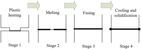
Figure 1. Mechanism of ultrasonic plastic welding
Figure 1 shows the mechanism of ultrasonic plastic welding. The specific welding process is as follows: 1) the plastic structural component contacts with the weld joint and generates heat (Stage 1); 2) the plastic structural component heats up and melts faster (Stage 2); 3) the thickness of the melted layer remains unchanged and the components fuse with each other steadily (Stage 3); 4) the ultrasonic vibration stops and the melted layer is cooled and solidified.
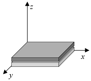
Figure 2. Plastic structural component model
Figure 2 shows the model of the plastic structural component to be welded. Based on the numerical simulation principle of viscoelastic heat, in the process of ultrasonic plastic welding, the energy generated in the deformation of the plastic structural component can be divided into two parts - stored potential energy and heat loss. In this paper, dynamic thermodynamic analysis was performed on the entire process to obtain the mechanical heating characteristics of ultrasonic welding at all frequencies. Since ultrasonic welding takes a very short time, it can be deemed that there is no heat convection between the plastic structural component and the air, and that the position of the structural component which the weld joint and the heat source are applied to is insulated.
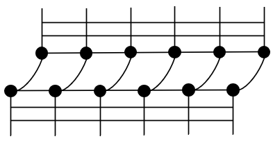
In this paper, the one-dimensional contact model is introduced to characterize the contact states of various interfaces in the ultrasonic plastic welding system, which helps achieve the numerical simulation of the physical state of the actual welding system, and improves the accuracy of calculation (Figure 3).
Figure 3. Plastic structural component interface contact model
Similar to those in the traditional arc welding, the basic forms of heat transfer in the process of ultrasonic plastic welding also include heat conduction, heat convection and heat radiation. Specifically, heat is transferred between the heat source and the plastic structural component mainly in the form of heat radiation and heat convection; and after the plastic structural component melts, the heat is internally transferred mainly in the form of heat conduction. In the simulation and calculation of the heat source temperature field in ultrasonic welding, it is necessary to pay more attention to the heat transfer process within the structural component dominated by heat conduction after the plastic structural component obtains heat, and at the same time consider the heat radiation and heat convection between the plastic structural component and the surrounding medium. With the aid of the heat efficiency of welding, the actual heat transfer between the heat source and the plastic structural component can be simplified.
Let the heat conduction and the temperature field in the process of ultrasonic plastic welding be denoted as E and (ψ2-ψ1), the heat conduction distance and the heat conduction area as L and S, the heat transfer duration as h, and the thermal conductivity as μ, and then under the fixed temperature gradient, the heat conduction in the ultrasonic plastic welding can be calculated by Formula (1):
$E=-\mu \left( \frac{{{\psi }_{2}}-{{\psi }_{1}}}{L} \right)Sh$ (1)
The material of plastic structural components is not as dense as that of metal structural parts. The heat conduction can be expressed as a unit differential equation, as shown in Formula (2):
$de=-\mu \frac{\partial \psi }{\partial L}$ (2)
Assuming that the convective heat transfer coefficient is represented by βDH, the heat convection between the plastic structural component and the surrounding medium can be characterized by Formula (3):
${{E}_{DH}}={{\beta }_{DH}}\left( \psi -{{\psi }_{A}} \right)Sh$ (3)
Let the temperature of the heat source be denoted as ψ, the air temperature around the plastic structural component as ψA, the thermal conductivity of the air and the air velocity as μA and θA, the air density, the specific heat capacity of the air and the air viscosity as σA, SHA and γ, respectively, and the shape coefficient of the heat source surface as ω, and then, the convective heat transfer coefficient βDH can be expressed by the function shown in Formula (4):
${{\beta }_{DH}}=g\left( \psi ,{{\psi }_{A}},{{\mu }_{A}},{{\theta }_{A}},{{\sigma }_{A}},S{{H}_{A}},\gamma ,\omega ,... \right)$ (4)
Let the ambient temperature be denoted as ψE, and the radiant heat transfer coefficient as ε, and then the radiant heat energy existing near the melted plastic structural component can be expressed by Formula (5):
$N=\varepsilon {{\left( \psi -{{\psi }_{E}} \right)}^{4}}$ (5)
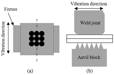
Figure 4 shows the top and side view of the welding set structure. As can be seen from the figure, when the ultrasonic plastic welding starts, the heat source instantly heats the plastic structural component to above the melting point. After the welding is completed, the plastic structural component quickly cools off. This heating process of the heat source is instantaneous, dynamic and locally concentrated. Therefore, the analysis of the heat source temperature field of ultrasonic plastic welding can be regarded as the investigation into the time-related nonlinear transient heat conduction problem. The temperature and thermophysical parameters of the plastic structural component constantly change during the movement of the heat source, and the process is also accompanied by the melting, cooling and solidification and the latent heat of the liquid-solid phase change of the plastic structural component. Therefore, the heat source temperature field of ultrasonic plastic welding is significantly uneven and unstable.
Figure 4. Top and side views of the welding set structure
Let the material density and specific heat capacity of the plastic structural component be denoted as σM and SHM, the thermal conductivity as μM, the distribution function of the welding heat source temperature field as F, and the endogenous heat rate as E, and then for the three-dimensional heat conduction problem of ultrasonic plastic welding, the governing equation of the heat source temperature field is expressed by Formula (6):
$\begin{align} & S{{H}_{M}}{{\sigma }_{M}}\frac{\partial F}{\partial h}=\frac{\partial }{\partial a}\left( {{\mu }_{M}}\frac{\partial F}{\partial a} \right)+\frac{\partial }{\partial b}\left( {{\mu }_{M}}\frac{\partial F}{\partial b} \right) \\ & +\frac{\partial }{\partial c}\left( {{\mu }_{M}}\frac{\partial F}{\partial c} \right)+E \\ \end{align}$ (6)
Let the direction cosines of the normals outside the weld boundary be denoted as ma, mb and mc, the temperature of the surrounding medium and the welding boundary as ψβ and ψH, respectively, and the heat exchange coefficient of the plastic structural component surface and the heat input per unit area as β and eH. And then, the boundary conditions required to solve Formula (6) are as follows:
1) The temperature on the welding boundary is described as the known first boundary condition:
${{\mu }_{M}}\frac{\partial F}{\partial a}{{m}_{a}}+{{\mu }_{M}}\frac{\partial F}{\partial b}{{n}_{y}}+{{\mu }_{M}}\frac{\partial F}{\partial c}{{m}_{c}}={{\psi }_{H}}\left( a,b,c,h \right)$ (7)
2) The heat flux density on the welding boundary is described as the known second boundary condition:
${{\mu }_{M}}\frac{\partial F}{\partial a}{{m}_{a}}+{{\mu }_{M}}\frac{\partial F}{\partial b}{{m}_{b}}+{{\mu }_{M}}\frac{\partial F}{\partial c}{{m}_{c}}={{e}_{H}}\left( a,b,c,h \right)$ (8)
3) The heat exchange between the welding boundary and the surrounding medium is described as the known third boundary condition:
${{\mu }_{M}}\frac{\partial F}{\partial a}{{m}_{a}}+{{\mu }_{M}}\frac{\partial F}{\partial b}{{m}_{b}}+{{\mu }_{M}}\frac{\partial F}{\partial c}{{m}_{c}}=\beta \left( {{\psi }_{\beta }}-{{\psi }_{H}} \right)$ (9)
The thermal process of ultrasonic plastic welding is a time-related transient nonlinear heat conduction problem, which reflects to a certain extent the temperature response mechanism of the plastic structural component that changes with time. In this paper, the finite element method and the finite difference method were used to analyze this problem. First, the solution domain of the governing equation of the heat source temperature field was discretized. Assuming that the shape function is denoted as [C] and that the temperature at the node of the element is denoted as {ψ}e, the temperature in this finite element can be expressed as:
$\left\{ \psi \right\}=\left[ C \right]{{\left\{ \psi \right\}}^{w}}$ (10)
Based on the weighted residual method, the following equation can be established:
$\left[ L \right]\left\{ \psi \right\}+\left[ \Phi \right]\frac{\partial \left\{ \psi \right\}}{\partial h}=\left\{ O \right\}$ (11)
The above formula contains 3 functions [L], [Φ] and {O} that vary with temperature, where [L] can be expressed as:
$\left[ L \right]=\sum{\left( {{\left[ {{L}_{1}} \right]}^{w}}+{{\left[ {{L}_{2}} \right]}^{w}} \right)}=\sum{\left( \int{_{\Delta U}}\left( \frac{\partial {{\left[ C \right]}^{T}}}{\partial a}l\frac{\partial \left[ C \right]}{\partial a}+\frac{\partial {{\left[ C \right]}^{T}}}{\partial b}l\frac{\partial \left[ C \right]}{\partial b}+\frac{\partial {{\left[ C \right]}^{T}}}{\partial c}l\frac{\partial \left[ C \right]}{\partial c} \right)dU+\int{_{\Delta R}}{{\left[ C \right]}^{T}}\beta \left[ C \right]dR \right)}$ (12)
$\left[ \Phi \right]=\sum{\left( {{\left[ \Phi \right]}^{w}} \right)}=\sum{\left( \int{_{\Delta U}}{{\left[ C \right]}^{T}}\sigma SH\left[ C \right]dU \right)}$ (13)
{O} can be expressed as:
$\left\{ O \right\}=\sum{\left( {{\left\{ {{O}_{1}} \right\}}^{w}}+{{\left\{ {{O}_{2}} \right\}}^{w}}+{{\left\{ {{O}_{3}} \right\}}^{w}} \right)}=\sum{\left( \int{_{\Delta U}}{{\left[ C \right]}^{T}}\overline{E}dU+\int{_{\Delta R}}{{\left[ C \right]}^{T}}edR+\int{_{\Delta R}}{{\left[ C \right]}^{T}}\beta {{\psi }_{\beta }}dR \right)}$ (14)
[L], [Φ] and {O} are nonlinear equations containing parameters like l, SH and β. Let the discrete time interval be denoted as ∆h. Discretize the solution domain of the governing equation at ∆h by the weighted difference method, and establish the differential formula at (h+∆h). After the Taylor series expansion of Formula (10), there is:
${{\left\{ \psi \right\}}^{\left( h+\phi \Delta h \right)}}=\phi {{\left\{ \psi \right\}}^{\left( h+\Delta h \right)}}+\left( 1-\phi \right){{\left\{ \psi \right\}}^{\left( h \right)}}+P\left( \Delta {{h}^{2}} \right)$ (15)
Calculate the partial derivatives on both sides:
$\frac{\partial }{\partial h}{{\left\{ \psi \right\}}^{\left( h+\phi \Delta h \right)}}=\frac{1}{\Delta h}{{\left\{ \psi \right\}}^{\left( h+\Delta h \right)}}+{{\left\{ \psi \right\}}^{\left( \theta \right)}}+P\left( \Delta {{h}^{2}} \right)$ (16)
Substitute the above two equations into Formula (11), and perform the same Taylor series expansion of {O}, and there is:
$\left( \frac{1}{\Delta h}\left[ {{\Phi }^{\phi }} \right]+\phi \left[ {{L}^{\phi }} \right] \right){{\left\{ \psi \right\}}^{\left( h+\phi \Delta h \right)}}=\left( \frac{1}{\Delta h}\left[ {{\Phi }^{\phi }} \right]+\phi \left[ {{L}^{\phi }} \right] \right){{\left\{ \psi \right\}}^{\left( h \right)}}+\phi {{\left\{ O \right\}}^{\left( h+\Delta h \right)}}+\left( 1-\phi \right){{\left\{ O \right\}}^{\left( \psi \right)}}$ (17)
The value range of the weighting factor φ is [0,1], which can be obtained by substituting the temperature value {ψ}(h+φ∆h) of the matrix [Φφ] and [Lφ] at (h+∆h). Here, different difference schemes correspond to different values of φ. The forward difference scheme φ is equal to 0, and the backward difference scheme φ is equal to 1. When φ is equal to 2/3, it is the Galerkin scheme with better accuracy and stability. It can be expressed as:
$\left[ DG \right]\left\{ \psi \right\}=\left\{ RE \right\}$ (18)
where, both [DG] and {RE} are functions that change with temperature. Use the Newton-Raphson method to convert the nonlinear transient heat conduction problem into a piecewise linear heat conduction problem, and there is:
$\left\{ \xi \left( \psi \right) \right\}=\left[ DG\left( \psi \right) \right]\left\{ \psi \right\}-\left\{ RE\left( \psi \right) \right\}$ (19)
Perform the first-order Taylor series expansion of Formula (19) at qt, and there is:
$\left\{ \xi \left( \psi \right) \right\}=\left\{ \xi \left( {{q}_{t}} \right) \right\}+\frac{\partial \xi \left( {{q}_{t}} \right)}{\partial \left\{ \psi \right\}}\left\{ \Delta \xi \right\}=0$ (20)
After equivalent transformation, the linear equation at the point qt is shown as Formula (21):
$\Delta {{q}_{t+1}}={{q}_{t+1}}-{{q}_{t}}=-{{\left[ \frac{\partial \left\{ \xi \left( {{q}_{t}} \right) \right\}}{\partial \left\{ \psi \right\}} \right]}^{-1}}\xi \left( {{q}_{t}} \right)$ (21)
Combine the above formula and Formula (18), and there is $\frac{\partial \left\{ \xi \left( {{q}_{t}} \right) \right\}}{\partial \left\{ \psi \right\}}$:
$\frac{\partial \left\{ \xi \left( {{q}_{t}} \right) \right\}}{\partial \left\{ \psi \right\}}d\left\{ \psi \right\}=\left[ DG \right]\left\{ d\psi \right\}+d\left[ DG \right]\left\{ \psi \right\}-d\left\{ RE \right\}$ (22)
In addition, [DG] and {RE} satisfy:
$d\left[ DG \right]\left\{ \psi \right\}=\left[ WS \right]d\left\{ \psi \right\}, dRE=\left[ FH \right]d\left\{ \psi \right\}$ (23)
Combine Formulas (22) and (23), and there is:
$\frac{\partial \left\{ \xi \left( \psi \right) \right\}}{\partial \left\{ \psi \right\}}=\left[ DG \right]+\left[ WS \right]+\left[ FH \right]$ (24)
Substitute the obtained {qt} into Formulas (23) and (20) to obtain {ξ(qt)}, [WSt], [FHt] and [DGt], and then combine Formulas (24) and (21) to obtain the iterative solution {qt+1}={qt}+{∆qt+1}. Continue the iteration until the stop condition is met, and the loop ends.
For ultrasonic welding that meets the given heat flow conditions and adiabatic conditions, complex conditions such as amplitude, welding pressure and welding time make the entire simulation process of the heat source temperature field very time-consuming. For thick and large plastic structural components, it can be deemed that the heat transfer of the heat source is dominated by heat conduction to shorten the calculation time and CPU consumption. For thin and light plastic structural components, all forms of heat transfer including surface heat dissipation should be fully considered.
Assuming that the surface heat dissipation coefficient and temperature of the plastic structural component are denoted as βS and ψW, the unit heat dissipation dE of any small-sized structural component can be expressed by Formula (25):
$dE=2{{\beta }_{S}}\left( {{\psi }_{W}}-{{\psi }_{A}} \right)dadbdh$ (25)
Assuming that the internal temperature change of the small-sized plastic structural component due to surface heat dissipation is dψ, there is:
$dE=-SH\cdot \sigma dUd\psi =-SH\cdot \sigma \cdot \varsigma \cdot dadbd\psi $ (26)
Assuming that the overall heat dissipation coefficient of the plastic structural component is denoted as κ, combine Formulas (25) and (26) and there is:
$\frac{d\psi }{dh}=-\frac{2{{\beta }_{S}}}{SH\cdot \sigma \cdot \varsigma }\psi =-\kappa \psi $ (27)
It can be seen from the above formula that κ is positively correlated with βS and inversely correlated with ς. In order to balance the temperature control accuracy of ultrasonic welding and the welding time consumption, it is necessary to decide whether to take surface heat dissipation into account in the simulation of the heat source temperature field according to the thickness of the plastic structural component.
The specific steps to simulate the heat source temperature field in ultrasonic plastic welding are as follows:
For a thin and light plastic structural component, there is no need to perform multi-layer and multi-pass welding, and thus, there is no weld pass division problem. For a thick and large plastic structural component, it is necessary to consider filling plastics, and calculate the height and volume of each pass in the multi-layer multi-pass welding. Let the ultrasonic welding pressure be denoted as DLS, the welding time as DIS, and the ultrasonic amplitude as EXS, the melting speed vLH can be expressed as:
${{v}_{LH}}=0.14D{{L}_{S}}-0.25+3.1\times {{10}^{-6}}\frac{E{{X}_{S}}}{D{{I}_{S}}^{2}}$ (28)
To mesh the calculation model constructed in this paper, it is necessary to reduce the mesh density as much as possible on the premise that the calculation accuracy, calculation amount and calculation cost all remain desirable.
In this paper, the method of element birth and death was introduced into the treatment and welding process of the whole weld. Let the number of weld passes of a thick plastic structural component be m, the number of analysis steps be 2m+1, the heat input per unit length of the weld be HIS, the volume of solder in a certain period of time be BT, the thermal efficiency coefficient characterizing the ratio between the total heat energy received by the plastic structural component and the total welding power be τ, then the heat flow per unit volume of the plastic structural component, that is, the heat generation rate, can be calculated by Formula (29):
$H{{I}_{S}}=\tau D{{L}_{S}}E{{X}_{S}}/BT$ (29)
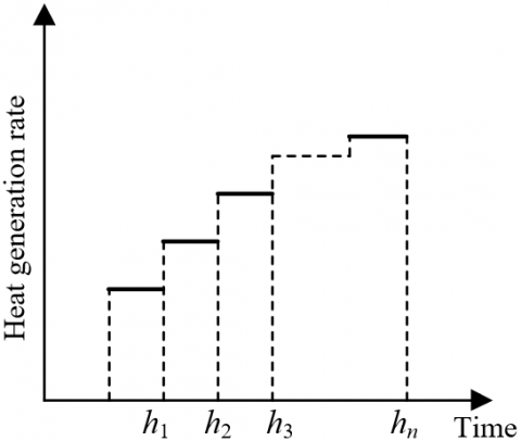
Figure 5. Curve of the heat generation rate with time
Assuming that the material properties of the plastic structural component change quasi-statically, it can be considered that the heat flow per unit volume is stable in a relatively short period of time and changes in a stepwise manner, as shown in Figure 5.
Regarding the calibration of welding heat source parameters, u, v, wg and wt are shape parameters that characterize weld width, depth of fusion and the length of the front and rear parts, respectively, used to determine the specific spatial area where the heat flow is distributed in the ultrasonic plastic welding process. In the actual welding process, there will be some loss of the heat generated during the cycle of the heat source due to the influences of heat conduction and welding conditions. The effective welding heat input can be expressed as:
$HI=\tau H{{I}_{0}}=\tau E{{X}_{S}}\cdot D{{L}_{S}}$ (30)
Assuming that the heat input parameters are represented by gg and gv, the heat input from the front part of the heat source can be expressed as:
$\begin{align} & 2\int_{0}^{\infty }{\int_{0}^{\infty }{\int_{0}^{\infty }{e}}}\left( a,b,c \right)dadbdc=\frac{6\sqrt{3}{{g}_{g}}{{e}_{0}}}{uv{{w}_{g}}\pi \sqrt{\pi }}\int_{0}^{\infty }{exp}\left( -\frac{3{{x}^{2}}}{{{u}^{2}}} \right)da\int_{0}^{\infty }{exp}\left( -\frac{3{{y}^{2}}}{{{v}^{2}}} \right)dy\int_{0}^{\infty }{exp}\left( -\frac{3{{c}^{2}}}{w_{^{g}}^{2}} \right)dc \\ & \text{ }=2\times \frac{6\sqrt{3}{{g}_{g}}{{e}_{0}}}{uv{{w}_{g}}\pi \sqrt{\pi }}\times \frac{u}{\sqrt{3}}\times \frac{\sqrt{\pi }}{2}\times \frac{v}{\sqrt{3}}\times \frac{\sqrt{\pi }}{2}\times \frac{{{w}_{g}}}{\sqrt{3}}\times \frac{\sqrt{\pi }}{2} \\ & \text{ }=\frac{1}{2}{{g}_{g}}H{{I}_{0}} \\ \end{align}$ (31)
The heat input from the rear part can be expressed by Formula (32):
$2\int_{0}^{\infty }{\int_{0}^{\infty }{\int_{0}^{\infty }{HI}}}\left( a,b,c \right)dadbdc=\frac{1}{2}{{g}_{g}}{{e}_{0}}$ (32)
So the numerator part of Formula (29) is:
$\tau D{{L}_{S}}\cdot E{{X}_{S}}=HI=\frac{1}{2}{{g}_{g}}{{e}_{0}}+\frac{1}{2}{{g}_{t}}{{e}_{0}}=\frac{1}{2}{{e}_{0}}\left( {{g}_{g}}+{{g}_{t}} \right)$ (33)
After simplification, there is:
${{g}_{g}}+{{g}_{t}}=2$ (34)
In this paper, an ultrasonic welding experiment was carried out on two plastic structural components. The frictional heat mainly came from the interface between the lower surface of the upper structural part and the upper surface of the lower structural part. The relative movements between the structural parts and the anvil blocks and between the weld joint and the upper surface of the upper structural part are ignored. Two thermocouples were used to measure the temperature at the same position on the interface between the lower surface of the upper structural part and the upper surface of the lower structural part and that between the weld joint and the upper surface of the upper structural part at the same time, and based on the measurement results, the interface temperature scatter diagram was plotted, as shown in Figure 6. It can be seen that the temperature of the measuring point on the interface between the lower surface of the upper structural part and the upper surface of the lower structural part changed faster, which proves that the main heat source in ultrasonic welding is the frictional heat between the lower surface of the upper structural part and the upper surface of the lower structural part.
Table 1 shows the weld width and fusion depth when the shape parameters u, v, wgand wt are of different values. It can be seen that when the measured values were taken for the four parameters, the simulation effect was the best, and that the pattern of influence on the peak temperature differed less. The main reason is that, in the space where the heat flow was distributed, with the increase of the parameter values, the heat energy tended to be more dispersed, and the pattern of influence on the size of the weld pool differed more.
Figure 6. Changes in the temperatures of the interfaces
Table 1. Melting of structural parts with different shape parameters
|
u |
0.0024 |
0.0035 |
0.00326 |
0.0036 |
0.0042 |
0.0046 |
|
Weld width |
0.0065 |
0.0067 |
0.00692 |
0.0065 |
0.0063 |
0.0067 |
|
Fusion depth |
0.00254 |
0.00253 |
0.00251 |
0.00253 |
0.00275 |
0.00217 |
|
v |
0.0013 |
0.003 |
0.0024 |
0.00257 |
0.005 |
0.0036 |
|
Weld width |
0.0075 |
0.0072 |
0.0063 |
0.00679 |
0.0063 |
0.0057 |
|
Fusion depth |
0.00235 |
0.00246 |
0.00241 |
0.00263 |
0.00234 |
0.00228 |
|
wg |
0.0013 |
0.003 |
0.0024 |
0.00257 |
0.005 |
0.0036 |
|
Weld width |
0.0075 |
0.0072 |
0.0063 |
0.00679 |
0.0063 |
0.0057 |
|
Fusion depth |
0.00235 |
0.00246 |
0.00241 |
0.00263 |
0.00234 |
0.00228 |
|
wt |
0.003 |
0.0024 |
0.004 |
0.0036 |
0.005 |
0.006 |
|
Weld width |
0.0063 |
0.0065 |
0.0068 |
0.00672 |
0.0067 |
0.0063 |
|
Fusion depth |
0.00235 |
0.00243 |
0.00267 |
0.00234 |
0.00221 |
0.00239 |
Table 2. Melting of the structural parts with different coefficients of thermal efficiency
|
Parameter |
τ |
|||||
|
0.6 |
0.7 |
0.75 |
0.8 |
0.9 |
0.95 |
|
|
Peak temperature |
1659 |
1872 |
2061 |
2315 |
2376 |
2492 |
|
Fusion depth |
0.00132 |
0.00175 |
0.00239 |
0.00245 |
0.00262 |
0.00291 |
|
Weld width |
0.00340 |
0.00537 |
0.00631 |
0.00678 |
0.0076 |
0.0085 |
|
Heat affected zone width |
0.0125 |
0.0136 |
0.0148 |
0.0131 |
0.0164 |
0.0137 |
Table 2 shows the weld width and fusion depth under different thermal efficiency coefficients. It can be seen that the numerical simulation result of the heat source temperature field is linearly correlated with the thermal efficiency coefficient. The fusion depth and the weld width increase with the increase of the thermal efficiency coefficient, and decrease with the decrease of the thermal efficiency coefficient. And unlike the heat-affected zone, the weld zone is more affected by the change in the value of the thermal efficiency coefficient.
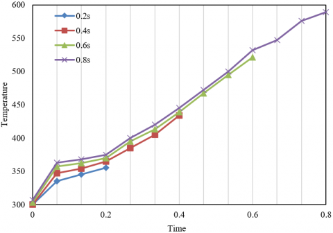
The total heat input to a plastic structural component is determined by the ultrasonic amplitude, the welding pressure and the welding time. Figure 7 shows the temperature change curves of the welding interface under four welding durations - 0.2, 0.4, 0.6 and 0.8. It can be seen that the welding duration is approximately linearly correlated to the highest value of the temperature change curve. If the welding interface needs to reach a higher temperature, a longer welding duration will be required.
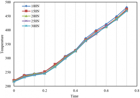
In order to avoid vibration of the weld joint before welding, it is necessary to make sure the weld joint is in close contact with the plastic structural component and apply a certain welding pressure before the ultrasonic welding is formally started. Figure 8 shows the temperature rise curve of the welding interface under different welding pressures. It can be seen that the temperature rise curves of the welding interface under five different pre-pressures - 100N, 150N, 200N, 250N and 300N highly overlap with each other. Increasing the welding pressure makes the welding temperature slightly lower, which further proves that the size of the welding pressure has little effect on the temperature of the welding interface.
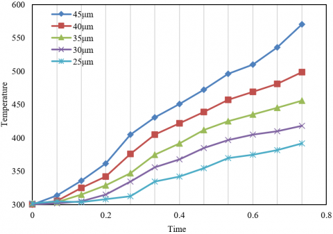
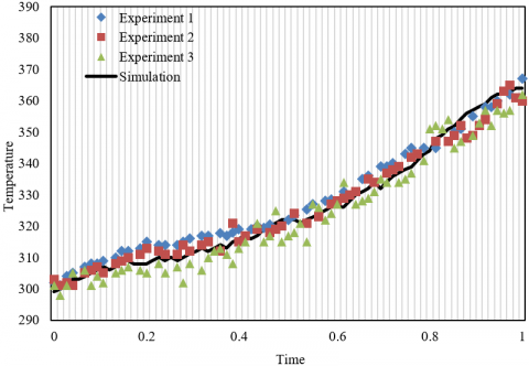
The ultrasonic amplitude will directly affect the vibration of the entire plastic structural component and the heating process of the welding interface. Figure 9 shows the temperature rise curves of the welding interface under different ultrasonic amplitudes. It can be seen that under the five different ultrasonic amplitudes - 25, 30, 35, 40 and 45μm, the temperature rise rate of the welding interface increases significantly with the increase of the ultrasonic amplitude. Figure 10 compares the results of the ultrasonic welding test and those of the numerical simulation. It can be seen that these results have good consistency at 11 time nodes in the whole welding process, with an error if less than 0.16. This proves the accuracy of the numerical simulation model for ultrasonic welding.
Figure 7. Temperature rise curves of the welding interface under different durations
Figure 8. Temperature rise curve of the welding interface under different welding pressures
Figure 9. Temperature rise curve of the welding interface under different ultrasonic amplitudes
Figure 10. Results of temperature rise from ultrasonic welding test and numerical simulation
This paper analyzed the heat source in the ultrasonic welding of plastic structural components based on numerical simulation. First, it elaborated in detail the basic heat transfer forms in the welding process, gave out the corresponding governing equations and boundary conditions, solved the governing equation of nonlinear transient heat conduction by the finite element method, and completed the numerical simulation on the temperature field of the heat source in the ultrasonic welding of plastic structural components. Then, it carried out ABAQUS thermal analysis and heat source parameter calibration on the welding heat source. The experiment section showed the melting status of the structural parts with different shape parameters and different thermal efficiency coefficients, and verified the linear correlation between the numerical simulation result of the heat source temperature field and the thermal efficiency coefficient. Heating curves of the welding interfaces under different durations, welding pressures and ultrasonic amplitudes were also drawn, which proved the accuracy of the proposed numerical simulation model for ultrasonic welding.
[1] Köhler, F., Villegas, I. F., Dransfeld, C., Herrmann, A. (2021). Static ultrasonic welding of carbon fibre unidirectional thermoplastic materials and the influence of heat generation and heat transfer. Journal of Composite Materials, 55(15): 2087-2102. https://doi.org/10.1177%2F0021998320976818
[2] Tutunjian, S., Eroglu, O., Dannemann, M., Modler, N., Fischer, F. (2020). A numerical analysis of an energy directing method through friction heating during the ultrasonic welding of thermoplastic composites. Journal of Thermoplastic Composite Materials, 33(11): 1569-1587. https://doi.org/10.1177%2F0892705719833108
[3] Han, W., Liu, J., Chong, D., Yan, J. (2016). Analysis of heat generation characteristics in ultrasonic welding of plastics under low amplitude conditions. Journal of Polymer Engineering, 36(4): 413-419. https://doi.org/10.1515/polyeng-2015-0214
[4] Shokri, V., Sadeghi, S., Sadeghi, M.H., Javadi, Y. (2015). Effect of heat input ratio on residual stress in multipass welding using finite element method and ultrasonic stress measurement. Journal of Nondestructive Evaluation, 34(3): 27. https://doi.org/10.1007/s10921-015-0301-0
[5] Volkov, S.S. (2015). Analysis of the process of heat generation in ultrasonic welding of plastics. Welding International, 29(4): 321-324. https://doi.org/10.1080/09507116.2014.921384
[6] Levy, A., Le Corre, S., Villegas, I.F. (2014). Modeling of the heating phenomena in ultrasonic welding of thermoplastic composites with flat energy directors. Journal of Materials Processing Technology, 214(7): 1361-1371. https://doi.org/10.1016/j.jmatprotec.2014.02.009
[7] Watanabe, T., Itoh, H., Yanagisawa, A., Hiraishi, M. (2009). Ultrasonic welding of heat-treatable aluminium alloy A6061 sheet. Welding International, 23(9): 633-639. https://doi.org/10.1080/09507110902842802
[8] Shi, L., Chen, J., Wu, C.S., Fu, L. (2021). Analysis of heat and mass transfer in ultrasonic vibration-enhanced friction stir welding of 2195 Al–Li alloy. Science and Technology of Welding and Joining, 26(5): 363-370. https://doi.org/10.1080/13621718.2021.1917748
[9] Khan, T.M., Maqsood, A., Warraich, S.A., Khalid, S. (2018). Postweld heat treatment characterization of mild steel (E6013) welded areas using wavelet transform of ultrasonic testing signals. Journal of Testing and Evaluation, 46(5): 2274-2280. https://doi.org/10.1520/JTE20160315
[10] Savu, I.D., Savu, S.V., Sebes, G. (2013). Preheating and heat addition by LASER beam in hybrid LASER-ultrasonic welding. Journal of Thermal Analysis and Calorimetry, 111(2): 1221-1226. https://doi.org/10.1007/s10973-012-2449-5
[11] Volkov, S.V., Shestel’, L.A., Sokolov, V.A. (2016). Heated tool ultrasonic welding of elastic containers produced from fluoroplastic film. Welding International, 30(6): 492-496. https://doi.org/10.1080/09507116.2015.1090180
[12] Gussev, M.N., Sridharan, N., Norfolk, M., Terrani, K.A., Babu, S.S. (2017). Effect of post weld heat treatment on the 6061 aluminum alloy produced by ultrasonic additive manufacturing. Materials Science and Engineering: A, 684: 606-616. https://doi.org/10.1016/j.msea.2016.12.083
[13] Rani, M.R., Prakasan, K., Rudramoorthy, R. (2015). Studies on thermo-elastic heating of horns used in ultrasonic plastic welding. Ultrasonics, 55: 123-132. https://doi.org/10.1016/j.ultras.2014.07.005
[14] Natesh, M., Yun, L., Vendan, S.A., et al. (2019). Experimental and numerical procedure for studying strength and heat generation responses of ultrasonic welding of polymer blends. Measurement, 132: 1-10. https://doi.org/10.1016/j.measurement.2018.09.043
[15] Volkov, S.S., Remizov, A.L., Kobernik, N.V. (2019). Features of the heat generation process at ultrasonic welding of polycarbonate under independent pressure. Welding International, 33(10-12): 405-410. https://doi.org/10.1080/09507116.2021.1894031
[16] Li, H., Cao, B., Yang, J. W., Liu, J. (2018). Modeling of resistance heat assisted ultrasonic welding of Cu-Al joint. Journal of Materials Processing Technology, 256: 121-130. https://doi.org/10.1016/j.jmatprotec.2018.02.008
[17] Jedrasiak, P., Shercliff, H.R. (2018). Finite element analysis of heat generation in dissimilar alloy ultrasonic welding. Materials & Design, 158: 184-197. https://doi.org/10.1016/j.matdes.2018.07.041
[18] Voigt, A.L., da Cunha, T.V. (2018). Effects of ultrasonic pulsation of the welding current on the geometry of the fusion zone and heat-affected zone in submerged arc welding. Welding International, 32(3): 172-178. https://doi.org/10.1080/09507116.2017.1347328
[19] Gu, X., Liu, D., Liu, J. (2018). Effect of post-weld heat treatment on the dissimilar Cu/Al joints produced by high power ultrasonic spot welding. ISIJ International, 58(9): 1721-1726. https://doi.org/10.2355/isijinternational.ISIJINT-2017-694
[20] Huang, H., Chen, J., Cheng, J., Lim, Y.C., Hu, X., Feng, Z., Sun, X. (2020). Surface engineering to enhance heat generation and joint strength in dissimilar materials AZ31 and DP590 ultrasonic welding. The International Journal of Advanced Manufacturing Technology, 111(11): 3095-3109. https://doi.org/10.1007/s00170-020-06341-3
[21] Zhao, W., Wu, C., Su, H. (2020). Numerical investigation of heat generation and plastic deformation in ultrasonic assisted friction stir welding. Journal of Manufacturing Processes, 56: 967-980. https://doi.org/10.1016/j.jmapro.2020.05.047
[22] Tsiangou, E., Kupski, J., de Freitas, S.T., Benedictus, R., Villegas, I.F. (2021). On the sensitivity of ultrasonic welding of epoxy-to polyetheretherketone (PEEK)-based composites to the heating time during the welding process. Composites Part A: Applied Science and Manufacturing, 144: 106334. https://doi.org/10.1016/j.compositesa.2021.106334
[23] Palardy, G., Villegas, I.F. (2017). On the effect of flat energy directors thickness on heat generation during ultrasonic welding of thermoplastic composites. Composite Interfaces, 24(2): 203-214. https://doi.org/10.1080/09276440.2016.1199149
[24] Javadi, Y., Azari, K., Ghalehbandi, S.M., Roy, M.J. (2017). Comparison between using longitudinal and shear waves in ultrasonic stress measurement to investigate the effect of post-weld heat-treatment on welding residual stresses. Research in Nondestructive Evaluation, 28(2): 101-122. https://doi.org/10.1080/09349847.2015.1123786
[25] Ohtani, T., Honma, T., Ishii, Y., Tbuchi, M., Hongo, H., Hirao, M. (2016). Nonlinear ultrasonic change in high cromium ferritic heat resisting steel welded joint during creep. Electromagnetic Nondestructive Evaluation (XIX), 41: 94-101. https://doi.org/10.3233/978-1-61499-639-2-94
[26] Liu, C., Shen, J., Yan, J., Chu, Q., Wang, J., Zhao, Y. (2020). Experimental investigations on welding stress distribution in thick specimens after postweld heat treatment and ultrasonic impact treatment. Journal of Materials Engineering and Performance, 29(3): 1820-1829. https://doi.org/10.1007/s11665-020-04731-y
[27] Huang, H., Chen, J., Lim, Y.C., Hu, X., Cheng, J., Feng, Z., Sun, X. (2019). Heat generation and deformation in ultrasonic welding of magnesium alloy AZ31. Journal of Materials Processing Technology, 272: 125-136. https://doi.org/10.1016/j.jmatprotec.2019.05.016