Syaiful* | Bambang Yunianto | Carisya Dara Salsabila | Berkah Fajar T.K. | Maria F. Soetanto
© 2021 IIETA. This article is published by IIETA and is licensed under the CC BY 4.0 license (http://creativecommons.org/licenses/by/4.0/).
OPEN ACCESS
In fin and tube heat exchangers, the gas passing through the fin has a lower thermal conductivity than the fluid passing through the tube. The low thermal conductivity brings a high thermal resistance, which suppresses the heat transfer rate. A common practice to enhance fin-side heat transfer is to generate longitudinal vortex by mounting vortex generators (VGs) on the fin. This paper aims to investigate how longitudinal vortex generator (LVG) improves heat transfer and pressure drop. Numerical simulations were carried out to analyze three types of VGs. The installation of VGs was varied with the attack angle changing from 10°, 15°, to 20° with a 1-3-4-7 VG arrangement on the tube. The flow velocity was expressed in Reynolds number (Re) between 364 and 689. The enhancement of heat transfer rate and improvement of pressure drop were analyzed between three types of VG, three different attack angles, and four types of winglet installation, compared to baseline. The simulation results show that the highest convective heat transfer coefficient (84.85%) was achieved by the VG composed of seven concave delta winglet pairs (CDWPs) at the attack angle of 20° and Re = 689; CDWP VG provides the highest heat transfer improvement among all cases.
longitudinal vortex, vortex intensity, heat transfer coefficient, thermal-hydrodynamic performance, synergy angle
Fin and tube heat exchangers are one of the tools that facilitate heat exchange between two fluids [1]. This compact heat exchanger is widely used in cooling systems, automobiles, aircrafts/spacecrafts, and petrochemical devices. One important feature of this heat exchanger is that the gas flows on the fin side. However, the high thermal resistance of the fin-side gas reduces the convective heat transfer coefficient, suppressing the transfer of heat. To improve the convective heat transfer coefficient, it is necessary to weaken the thermal resistance through modification of the fin section [2]. This passive method can effectively enhance the heat transfer in the heat exchanger, and increase the pressure drop flow, which is the concern of many researchers [1].
Gholami et al. stated that a traditional way to reduce gas-side thermal resistance is to increase the surface area of the heat exchanger [3], and modified the fin section with the protrusion of a surface, which improves the overall performance of heat transfer. This traditional approach works well, especially in cooling systems, because the gas side is dominated by high thermal resistance. There are various forms of surface protrusions, such as plain, wavy, louver, slit, and offset [4]. Nevertheless, surface protrusions could push up the production price [3]. To solve this problem, several methods have been proposed to increase the rate of heat transfer. One of these methods decreases thermal resistance by thinning the thermal boundary layer between the fluid and the wall [5].
Modification with surface protrusion is a passive method that can generate vortices on the fin surface, thereby boosting the heat transfer on the gas side [6]. The passive method responsible for creating swirling flow and generating vortices is vortex generator (VG). Delta wings, rectangular wings, delta winglet pairs, and rectangular winglet pairs (RWPs) are types of VGs that can be installed by punching, embossing, welding, or stamping. Nonetheless, the secondary flows triggered by longitudinal vortices will disrupt the formation of thermal boundary layers and cause flow instability, which in turn produces turbulence with high scale [7]. In addition, the vortices generated by longitudinal VG (LVG) last a long time until reaching the downstream region [8].
Many scholars have tried to increase the convective heat transfer coefficient using a VG. Through three-dimensional (3D) modeling, Naik and Tiwari [9] studied the effect of winglet locations on heat transfer features in fin and tube heat exchangers using inline RWPs, and observed that the Nusselt number (Nu) and secondary flow intensity (Se) peaked at ∆Y = ± 1.25 and attack angle (β) = 45°, which are mounted in the downstream area adjacent to the tube. Lu and Zhai [10] numerically analyzed the heat transfer and pressure drop on a fin and oval tube heat exchanger using a tear-drop delta VG, found that the tear-drop delta GV outperforms plain delta VG, and investigated the mechanism of the advantage in the light of Se and field synergy principle.
Through both experiments and numerical simulation, Salleh et al. [11] explored the thermal-hydraulic performance of fluid flow passing through the fin and tube heat exchanger with and without a trapezoidal winglet vortex generator (TWVG); the experimental results show that heat transfer could be increased by changing the geometry, installation configuration, aspect ratio (Λ), and attack angle (β) on TWVG; the simulation results illustrate that flat trapezoidal winglets mounted with a common flow-up orientation at Λ = 3 and β =10° lead to the best thermal-hydraulic performance, as evidenced by the increased heat transfer and decreased pressure drop. Lu and Zhai [12] numerically evaluated the heat transfer performance and flow structure of using curved VGs on fin and tube heat exchangers, and discovered that: Se increases with the radius of curvature of the curved VG, and VGs with curvature of 0.25, β = 15°, and radius R = 1.06 boast the best thermal-hydraulic performance.
Syaiful [13] conducted experiments to analyze the effect of concave RWPs (CRWPs) on the thermal-hydraulic performance of flow in channels, revealing that the mounting of three CRWPs with β = 45° elevated the convective heat transfer coefficient by 188% from the level of the baseline; yet the increase of VG pairs and attack angle increased the pressure drop. Song et al. [14] numerically identified the heat transfer features of concave and convex curved VGs in the channels of laminar flow, and drew the following conclusions: concave curved VG outshines curved convex VG and plain VG in heat transfer; concave curved VG had a 11.3% higher thermal performance factor (JF) at Re = 1400, β = 20°, and subtended angle θ = 80, compared to that of convex curved VG. Through numerical investigation, Syaiful et al. [15] attempted to increase heat transfer in fin and tube heat exchangers by adding CRWPs; the greatest increment of convective heat transfer coefficient was found in seven rows of RWPs (38.1%) and CRWPs (102.5%) with β = 15°; CRWPs brought the greater increment, as it produces stronger LVG than RWP.
The previous research shows that an increase of convective heat transfer coefficient is always accompanied by an increase in pressure drop, which causes low thermal-hydraulic performance. Based on the evaporator experiments conducted by Joardar and Jacobi [16], this paper carries out numerical simulations to compare two novel VGs, namely, concave delta winglet pairs (CDWPs) and convex delta winglet pairs (CxDWPs) with delta winglet pairs (DWPs) and baseline, with variations in attack angle (α): 10°, 15°, and 20°. The purpose is to improve convective heat transfer and pressure drop with variations in VG types and attack angles of fin and tube heat exchangers.
2.1 Physical model
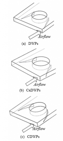
3D numerical simulation was performed on three types of VG with three kinds of attack angles and four types of VG installations arranged with a common flow up orientation. Figure 1 shows the geometry of each VG; Figure 2 shows the dimensions of VGs and their placement on the tube; Figure 3 offers the side view of the VGs.
The trailing edge of each VG was arranged at 6.4mm from the midpoint of the tube. For concave and convex VGs, the radius of curvature was set to 21mm. The height (H) of each VG is 60% of the channel height. The attack angle (α) was varied from 10°, 15°, to 20°. The installation configuration was performed on the VG for successive tubes, namely, one VG pair on the first tube; three pairs of VG on the first, third and fifth tubes; four VG pairs on the first, third, fifth and seventh tube; seven VG pairs on all tubes.
Figure 1. Geometry of VGs
Figure 2. Dimensions of VGs and their placement on the tube (mm): (a) DWPs; (b) CxDWPs; (c) CDWPs
Figure 3. VG dimension (side view)
The computational domain of the numerical model is determined as shown in Figure 4, where the Cartesian coordinates (x, y) are the directions of streamwise and spanwise flow, and coordinate (z) is the normal flow towards the wall; the dashed lines mark the computational domain for geometry modeling.
The aluminum fins mounted on the top and bottom form a channel that has a height of H = 3.63 mm, length of L = 177.8 mm, and width of B = 12.7 mm. The thickness of each fin is Ft = 0.18 mm. The distance between the inlet and the midpoint of the first tube is 12.7 mm, while the distance between the next tube and the outer diameter of the tubes (P1 and Ps) are 25.4 mm and D = 10.67 mm, respectively.
In fin and tube heat exchangers, heat transfer is dominated by convection. However, the conductive heat transfer at fin, which is expressed as temperature distribution, cannot be ignored entirely [17]. Thus, conjugate heat transfer was solved by the side-view computational domain in Figure 4(b), as indicated by the dotted lines, in this modeling.
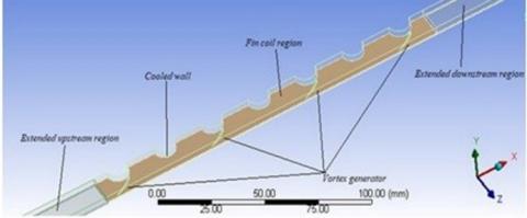
Figure 5 provides the 3D view of a computational domain. The computational domain consists of three parts: extended upstream region, fin coil region, and extended downstream region. The extended upstream region is an extension of the inlet to ensure the full development of the flow entering the channel. The fin coil region lies between the upstream and downstream areas; the VG and tube are mounted right here. In addition, the outlet was extended into the extended downstream region to prevent reverse circulation as the fluid flows out.
Figure 4. Computational domain in a fin and tube heat exchanger
Figure 5. 3D view of a computational domain
2.2 Governing equations
In our 3D numerical simulation, the gas passing through the fin was assumed to be an incompressible flow with constant physical properties. The Re was controlled between 364 and 689, making the gas a laminar flow. The temperature distribution on fin surface is determined by the thickness of the fin and conductive heat transfer at the fin. On this basis, the governing equations can be established as follows:
Continuity equation:
$\frac{\partial}{\partial x_{i}}\left(\rho u_{i}\right)=0$ (1)
Momentum equation:
$\frac{\partial}{\partial x_{i}}\left(\rho u_{i} u_{k}\right)=-\frac{\partial p}{\partial x_{k}}+\frac{\partial}{\partial x_{i}}\left(\mu \frac{\partial u_{k}}{\partial x_{i}}\right)$ (2)
Energy equation:
$\frac{\partial}{\partial x_{i}}\left(\rho u_{i} T\right)=\frac{\partial}{\partial x_{i}}\left(\Gamma \frac{\partial T}{\partial x_{i}}\right)$ (3)
where, ρ, p, u, μ, and T are the density, pressure, mean x-axis velocity, dynamic viscosity of air, and temperature, respectively; G is the diffusion coefficient defined as $\Gamma=\frac{\lambda}{c_{p}}$, with λ and cp being thermal conductivity and specific heat of fluid, respectively.
2.3 Boundary conditions
The boundary conditions for all computational domains are described as follows:
• At the inlet boundary
$u=u_{i n}, v=w=0, T=T_{i n}=\text { Const }$. (4)
• At the top and bottom boundaries
Velocity condition: periodic condition, uup = udown
Temperature condition: periodic condition, Tup = Tdown
• At the outlet boundary
$\frac{\partial u}{\partial x}=\frac{\partial v}{\partial x}=\frac{\partial w}{\partial x}=\frac{\partial T}{\partial x}=0$ (5)
• At the top and bottom boundaries
Velocity condition: periodic condition, uup = udown
Temperature condition: periodic condition, Tup = TdownFin coil region
• At the top and bottom boundaries
Velocity condition: periodic condition, uup = udown
Temperature condition: periodic condition, Tup = Tdown
• At the side boundaries
$\text { Cooled wall: } u=v=w=0, T=T_{w}$ (6)
$v=0, \frac{\partial u}{\partial y}=\frac{\partial w}{\partial y}=\frac{\partial T}{\partial y}=0$ (7)
2.4 Numerical method
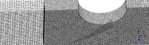
3D simulations require a high accuracy, due to the complex geometries of the objects. The simulation accuracy of shape and size can be ensured by adjusting the shape and type of grids. Figure 6 shows the meshing of the computational domain. The extended upstream region and the extended downstream region were meshed into hexahedral elements, because the two regions are simple in shape. Meanwhile, the VG and tube domain, i.e., the fin coil region, was meshed into tetrahedral grids to accurately simulate the complex geometry of this region.
The governing Eqns. (1)-(3) with boundary conditions (4)-(7) were solved on Fluid Dynamics (CFD). The laminar model was used in the current simulation. The semi-implicit method for pressure linked equations (SIMPLE) algorithm was used to solve the correlation between velocity and pressure. The governing equations for momentum and energy were discretized with the second-order upwind scheme. The convergence criteria were set to 10-5 for continuity equations and 10-8 for energy equation.
Figure 6. Meshing
2.5 Parameter definition
The parameters used in this study are as follows:
Reynolds number,
$R e=\frac{\rho u_{m} D_{h}}{\mu}$ (8)
Nusselt number,
$\overline{N u}=\frac{h D_{h}}{\lambda}$ (9)
where, r, um, µ, and λ are the density, mean fluid velocity in the flow direction, dynamic viscosity, and thermal conductivity, respectively; Dh is the hydraulic diameter defined as $D_{h}=4\left(A_{\min } L\right) / A_{T}$. The convective heat transfer coefficient (h) can be defined as:
$h=\frac{q}{A_{T} \Delta T}$ (10)
where, q, AT, and ∆T are the convective heat transfer rate, total surface area of heat transfer, and mean logarithmic temperature difference, respectively. The latter two parameters can be described as:
$q=\dot{m} c_{p}\left(\bar{T}_{\text {out }}-\bar{T}_{\text {in }}\right)$ (11)
$\Delta T=\frac{\left(T_{w}-T_{\text {in }}\right)-\left(T_{w}-T_{\text {out }}\right)}{\ln \left(\frac{T_{w}-T_{i n}}{T_{w}-T_{\text {out }}}\right)}$ (12)
where, Tw, Tin, and Tout are cooled wall temperature, inlet temperature, and outlet temperature, respectively; $\dot{m}$ is the mass flow rate defined as $\dot{m}=\rho u A_{c}$, with Ac being the cross-sectional area as the fluid flows into the channel.
London area goodness factor is defined as the ratio of Colburn factor (j) to friction factor (f):
$j=S t \cdot \operatorname{Pr}^{2 / 3}$ (13)
$S t=\frac{h}{\rho u_{m} c_{p}}$ (14)
$f=\frac{2 \Delta P}{\rho u_{m}^{2} \frac{A_{T}}{A_{\min }}}$ (15)
where, Amin is the minimum cross-sectional area; ∆P is the pressure drop of fluid flow through the heat exchanger defined as ∆P = Pin - Pout.
2.6 Validation
Figure 7. Comparison between the results of Joardar and Jacobi’s experiment and those of our study
A grid independence test was carried out at the Re of 524 to ensure that the simulation results are independent of the number of grids. Three grid numbers (1,200,000, 1,400,000 and 1,600,000) were tested. The 1,400,000 grids were selected as independent grids, because the heat transfer coefficient remained basically constant after using this number.
In this work, geometry is made according to experiments carried out by Joardar and Jacobi. Validation was performed by comparing the simulated results on convective heat transfer coefficient and pressure drop with the experimental results, as the Re changed from 523 to 942 (Figure 7).
By comparing simulated results with experimental results, the authors discussed the effect of variations in VG shape, attack angle, and number of VG installations on flow structure and thermal-hydraulic performance. Previous studies have shown that VGs are efficient tools to enhance convective heat transfer, because they can bolster flow turbulence and disrupt the formation of thermal boundary layers [14].
3.1 Velocity streamline and vector
Figure 8 shows the streamline at Re = 689 by comparing installations without VG (baseline), and installation of seven pairs of VGs. It can be found that different flow patterns were observed for the use of different VGs.
The streamline at the baseline shows a uniform distribution of flow velocity (Figure 8 (a)), while the use of VG generated swirling motion in the flow. The swirling motion in the wake area of the VG indicates the formation of longitudinal vortices, which facilitate fluid exchange in the main flow and the near-wall region [18]. With the common flow-up flow orientation, the generated longitudinal vortices exhibited counterrotation, under the interaction of centrifugal forces and the difference in pressure in the spanwise direction [19]. The counterrotating longitudinal vortices produced downwash regions that carry the flow from the main flow towards the wall and upwash regions that carry outflow into the main flow [20].
Swirl flow was clearly observed under the influence of VG geometry, as shown in Figures 8 (b)-(d). The CDWP geometry produced a stronger swirl flow than that of CxDWP, for the frontal surface of CDWP is wider than that of CxDWP. However, the swirl flow (longitudinal vortices) generated by a pair of VGs was found to weaken in the downstream direction. The longitudinal vortices could not last long under the recirculation effect of the flow behind the tube [9]. This problem was solved by adding VG pairs. Then, the longitudinal vortices, which faded after passing through the first wake region, were reinforced with the VG in the second row, as it hit the leading edge of the winglet. The installation of VGs on each tube enhances the counterrotating longitudinal vortices, such that swirl flow can last until the downstream. In addition, the common flow-up orientation causes the vortices on the left to rotate clockwise and those on the right to rotate counter-clockwise towards the center of the channel. Both of these vortices destroy the thermal boundary layer, and drive up heat transfer [21].
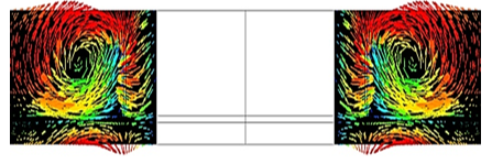
As can be seen in Figure 9, the main vortex and corner vortex were produced in the downstream of VGs. The main vortex comes from the separation at the leading edge of the winglet, while the corner vortex originates from the junction between the fin and the stagnation area caused by the pressure difference on the winglet side [14].
Figure 10 compares the tangential velocity vectors in cross-section area with common flow-up orientation in DWPs, CxDWPs, and CDWPs. Vorticities were clearly observed behind VGs on the cross-section plane (spanwise). The intensity of the longitudinal vortex faded into the downstream region, due to viscous dissipation [14], and was then enhanced by the VGs behind the region. Judging by streamline and tangential velocity vectors, CDWPs produced greater and more intense vortices than CxDWPs and DWPs.
Figure 8. Comparison of streamline of longitudinal vortex at several cross-sections at Re = 689 and α = 20º
Figure 9. Main vortex and corner vortex at installation of seven pairs of CDWP with Re = 689 and α = 20º at x/L = 15.5
Figure 10. Tangential velocity vector of seven pairs VGs at X1, X2, and X3 for Re = 689 with angle attack of 20°
3.2 Longitudinal vortex intensity
Longitudinal vortex intensity refers to the ratio of the inertia force induced by secondary flow to viscous force [2]. Longitudinal vortex intensity (Se) can be obtained by:
$S e=\frac{\rho D_{h} U}{\mu}$ (16)
where, U is the feature of secondary flow:
$U=D_{h}\left|\omega^{n}\right|=D_{h}\left|\frac{\partial w}{\partial y}-\frac{\partial v}{\partial z}\right|$ (17)
where, $\omega^{n}$ is the vorticity component in the normal direction with respect to the transverse axis. The mean longitudinal vortex intensity in the spanwise direction can be defined as:
$S e_{x}=\frac{\rho D_{h}^{2}}{A(x) \mu} \iint_{A(x)}\left|\omega^{n}\right| d A$ (18)
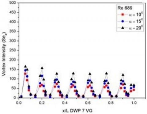
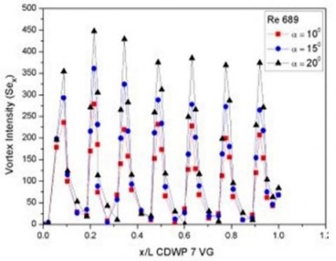
Figure 11 compare the local longitudinal vortex intensity (Sex) for seven pairs of VGs at different attack angles. It can be inferred that CDWPs generated a more intense longitudinal vortex than DWPs, as the centrifugal force is instable when the flow passes through the concave wall [22]. For the CxDWPs, the convex geometry narrows the channel, which accelerates the flow through the VG. That is why CxDWPs led to a stronger longitudinal vortex than DWPs. But the vortex produced by CxDWPs was relatively weak, as the pressure difference on the downstream and upstream side of the VG is lower than that of CDWPs [14].
(a) DWPs
(b) CxDWPs
(c) CDWPs
Figure 11. Local vortex intensity at different attack angles and Re = 689
As the attack angle increased from 10º to 20º, the longitudinal vortex became more intense, a sign of stronger vortex circulation [13]. From Figure 11, it can be observed that the decrease in the longitudinal vortex on a single VG pair is caused by viscous dissipation, as the fluid flows downstream. However, the longitudinal vortex was enhanced again with the addition of VG pairs [10]. Figures 11 (a)-(c) show that the installation of seven pairs of CxDWP and CDWP increased the longitudinal vortex intensity by 36.9% and 185.23%, respectively, against DWP Re = 689 with an attack angle of 20º at x/L = 0.21.
3.3 Temperature distributions
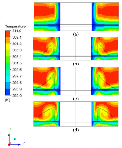
Figure 12. Temperature distribution for seven pairs of VGs in streamwise section at Re = 689 and attack angle of 20° for the case of: a. baseline, b. DWP, c. CxDWP, and d. CDWP
Figure 12 illustrates the temperature distributions for baseline, DWPs, CxDWPs, and CDWPs in an installation configuration of seven pairs of VGs with Re = 689 and an attack angle of 20°. The temperature distributions were observed in the streamwise direction at Y=1.5 mm. It can be found that low temperature appeared behind the tube, and high temperature existed before and on the side of the tube, under the action of horseshoes and longitudinal vortices [9]. Low temperatures were distributed in the wake region, where the flow is slow and heat transfer is limited. To increase heat transfer, the wake region was weakened to strengthen the fluid mixture. VG installation induced a high-temperature gradient around VG, and generated a secondary flow. Then, the secondary flow mixed with the flow in the wake region of the tube, which causes the thinning of the thermal boundary layer and a significant increase in heat transfer [23].
As shown in Figure 12, CDWPs achieved better temperature distribution than CxDWPs and DWPs. The strongest longitudinal vortex was generated by CDWPs, thanks to the effect of the centrifugal force on the surface curvature of the VGs. The vortices carry the cold fluid from the wake region to the main flow and vice versa. The wake region is thus narrowed, resulting in a high-temperature gradient [1].
The longitudinal vortices generated by VG causes the thinning of the thermal boundary layer in the downwash region of the wake tube, and leads to an increase in heat transfer. After the fluid passes through the downwash region, the boundary layer again thickens in the upwash region. The addition of VG pairs reinforces the longitudinal vortex, so that the fluid is mixed evenly with the installation of VG to the downstream region.
As shown in Figure 13(a), a low temperature area was observed near the wall at x/L = 0.084 and Re = 689 for the baseline. For the same case, the installation of VG causes the mixing between the high temperature in the main flow and the low temperatures near the wall (Figures 13(b)-(d)). This phenomenon occurs because the generated longitudinal vortices increase mixing and thins the thermal boundary layer [19]. From Figures 13 (b)-(d), it can be found that the temperature gradient became more evenly distributed with the increase in the attack angle, which indicates the growing mixing of the fluid in the main flow with that near the tube wall [5].
Figure 13. Temperature distribution at Re = 689 for x/L = 0.084 behind first pair of VGs for the case of: (a) baseline; α = 20° seven pairs of VGs for: (b) DWP, (c) CxDWP, and (d) CDWP
3.4 Pressure distributions
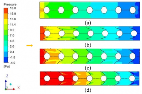
Figure 14. Pressure distribution at Re = 689 and α = 20° for; (a) baseline (b) seven pairs of DWP VGs; (c) seven pairs of CxDWP VGs; and (d) seven pairs of CDWP VGs
Figure 14 compares the pressure distribution of baseline with that of seven pairs of DWP, CxDWP, and CDWP at Re = 689 and attack angle of 20º. It can be observed that CDWPs had the highest pressure drop, for the concave geometry has a broad frontal area that inhibits the main flow rate [14]. Compared with CDWPs, CxDWPs had a relatively small increase in pressure drop. The longitudinal vortex generated by CxDWP is lower than that of CDWP, so the flow resistance is relatively small [14].
3.5 Effect of angle attack on convective heat transfer coefficient (h)
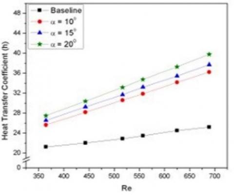
The convective heat transfer coefficient could be increased by increasing the Reynolds number, the VG geometry, and the attack angle of the fin and tube heat exchanger. Figure 15 displays the effect of the Reynolds number on the convective heat transfer coefficient (h) for the DWP, CxDWP, and CDWP cases. Obviously, the convective heat transfer coefficient increased with the Reynolds number. There are two possible reasons: First, the high-velocity flow generates stronger longitudinal vortices than low-velocity flow [9]. Second, CDWPs produce greater convective heat transfer coefficients than CxDWPs and DWPs, by virtue of its relatively wide contact area [17].
(a) DWPs
(b) CxDWPs
(c) CDWPs
Figure 15. Comparison of convective heat transfer coefficients at different attack angles for seven pairs of VG
The flow passing through the concave area is destabilized by the centrifugal force on the curvature of the CDWPs. The instable flow would generate a strong longitudinal vortex [22]. The convective heat transfer coefficient could be scaled up by increasing the attack angle. As the angle widens, the longitudinal vortex becomes stronger. Then, the cold fluid near the wall would exchange with the hot fluid in the main flow. The ensuing secondary flow could increase the convective heat transfer coefficient [18]. The heat transfer is enhanced as the flow through the first pair of VG triggers the generation of longitudinal vortices and fades in the wake region. Further, the addition of VG pairs reinforces the intensify of the longitudinal vortex, and increases the convective heat transfer coefficient [2]. At the attack angle of 10° and Re = 689, the convective heat transfer coefficients of DWPs, CxDWPs, and CDWPs increased by 33.76%, 43.59%, and 73.01%, respectively, against the baseline.
Meanwhile, the convective heat transfer coefficients of DWPs, CxDWPs, and CDWPs increased by 41.11%, 49.42%, and 79.50%, respectively, against the baseline, at the attack angle of 15° and Re = 689. When the attack angle was 20º and Re = 689, the maximum convective heat transfer coefficients of DWPs, CxDWPs, and CDWPs were 50.25%, 57.71%, and 84.85% greater than that of the baseline, respectively. However, the increase in the convective heat transfer coefficient, triggered by the growth of Re, the geometry of the VG, the angle of attack, and the number of VG pairs, could intensify the pressure drop [19].
3.6 Effect of parameters on pressure drop (∆P)
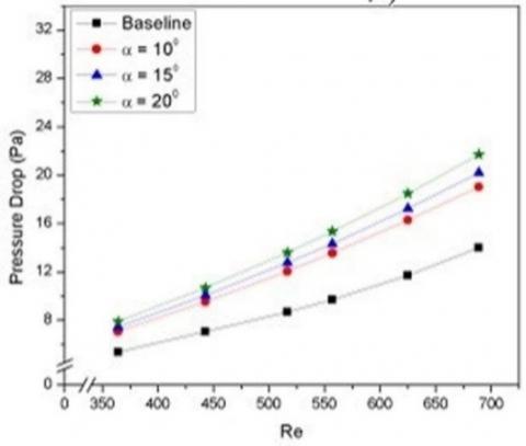
Besides elevating the convective heat transfer coefficient, VG installation magnifies pressure drop by obstructing the main flow on the air side [24]. The greater the Re, the more significant the pressure drop. With a common flow up orientation, the flow passing through the VG reinforces the frictional force on the wall and the local resistance of the VG, inducing an increase of pressure drop [21]. Figure 16 compares the pressure drops of CDWPs, CxDWPs, and DWPs at different attack angles, as Re changed from 364 to 689. As in the previous cases, the drag force generated by CDWPs was greater than that of CxDWPs or DWPs. As a result, the recirculation region expanded behind the VG, which enlarged the drag force [11]. The installation of seven pairs of VG not only boosted the heat transfer coefficient, but also reinforced pressure drop. As the attack angle changed from 10º to 20º, the seven pairs of DWP, CxDWP, and CDWP increased the pressure drop by 49.07%, 58.24%, and 128.74%, respectively, against the baseline. The intensity growth of the longitudinal vortex in CDWPs was greater than that of CxDWPs or DWPs, owing to the differences in pressure and friction [25]. That is why CDWP VGs witnessed the largest increment of pressure drop.
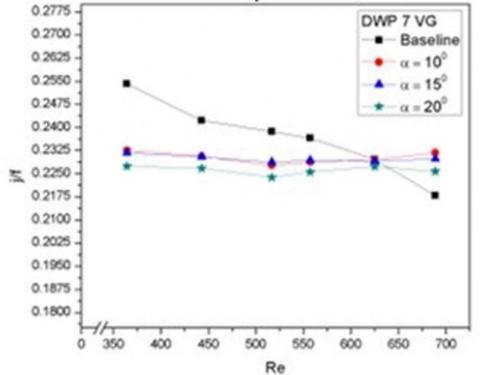
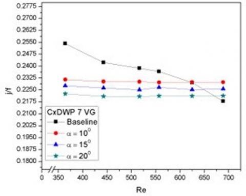
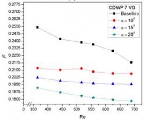
3.7 Effect of parameters on thermal-hydraulic performance
Empirical evidences show that a rise in convective heat transfer rate is followed by an increase in pressure drop. London area goodness factor (j/f) was introduced to evaluate the overall thermal-hydraulic performance of fin and tube heat exchangers [21]. As mentioned before, the factor is defined as the ratio of Colburn factor to friction factor, which are represented by heat transfer coefficient and pressure drop, respectively. Figure 17 compares the London area goodness factors of DWPs, CxDWPs, and CDWPs by adjusting the attack angle for the seven pairs of VGs. The growing attack angle increased the pressure drop induced by the VG’s drag force, thus weakening the thermal-hydraulic performance. As shown in Figure 17, the j/f ratio obviously declined in the installation of seven pairs of VGs. At the attack angle of 10°, the j/f ratios of the seven pairs of DWPs, CxDWPs, and CDWPs were 0.231, 0.229, and 0.206, respectively, against the baseline. At the attack angle of 15°, the j/f ratios of the seven pairs of DWPs, CxDWPs, and CDWPs were 0.229, 0.225, and 0.195, respectively, against the baseline. At the attack angle of 20°, the j/f ratios of the seven pairs of DWPs, CxDWPs, and CDWPs were 0.225, 0.221, and 0.178, respectively, against the baseline.
(a) DWPs
(b) CxDWPs
(c) CDWPs
Figure 16. Comparison of pressure drops at different attack angles for seven pairs of VG
(a) DWPs
(b) CxDWPs
(c) CDWPs
Figure 17. Thermal-hydrodynamic performance at different attack angles for seven pairs of VG
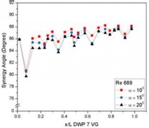
3.8 Field synergy principle analysis
Proposed by Guo et al. [26], field synergy principle is a method to measure the increase in heat transfer. The increment is obtained by reducing the intersection angle between the velocity vector and the temperature gradient, that is, the synergy angle. Inspired by Guo et al. [33], the synergy angle is obtained by the energy balance equation:
$\rho c_{p} \int_{0}^{\delta_{t}}(U \cdot \nabla T) d y=-\lambda \frac{\partial T}{\partial y}$ (19)
where, $\rho, c_{p}, \text { and } \lambda$ are assumed to be constant. Thus, the dimensionless form of formula (19) can be given by:
$R e_{x} \operatorname{Pr} \int_{0}^{1}(\vec{U} \cdot \nabla \vec{T}) d \vec{y}=N u_{x}$ (20)
where, $\vec{U}=\frac{U}{U_{\infty}} ; \nabla \vec{T}=\frac{\nabla T}{\left(T_{\infty}-T_{w}\right) / \delta_{t}} ; \vec{y}=\frac{y}{\delta_{t}}$, with $U_{\infty} \text { and } T_{\infty}$ being the velocity and temperature of the fluid in the freestream region, respectively, and $\delta_{t}$ being the thickness of thermal boundary layer.
Meanwhile, $(\vec{U} \cdot \nabla \vec{T})$ in formula (20) can be described as:
$(\vec{U} \cdot \nabla \vec{T})=|\vec{U}||\nabla \vec{T}| \cos \theta$ (21)
$\cos \theta=\frac{(\vec{U} \cdot \nabla \vec{T})}{|\vec{U}||\nabla \vec{T}|}$ (22)
where, θ is the synergy angle.
Figure 18 compares the synergy angles at different attack angles and Re=689 for seven pairs of VG. It can be seen that the high longitudinal vortex appearing at Re = 689 reduced the synergy angle [21]. At the attack angle of 20º and Re = 689, the synergy angles at the installation of seven pairs of DWP, CxDWP, and CDWP dropped to 79.74°, 79.13°, and 78.76°, respectively. The decline of synergy angle is influenced by the type of VG. The VG types can be ranked in descending order of the synergy angle as CDWPs, CxDWPs, and DWPs. The synergy between velocity vector and temperature gradient is modified by longitudinal vortices, whose strength depends on VG curvature [18].
(a) DWPs
(b) CxDWPs
(c) CDWPs
Figure 18. Local synergy angles at different attack angles and Re=689 for seven pairs of VG
This paper improves convective heat transfer using DWP, CxDWP, and CDWP VGs by varying the attack angle from 10º to 20º, and numerically analyzes their effect on the pressure drop in fin and tube heat exchangers. From the research, it can be concluded that:
(1) The intensity of longitudinal vortex in the installation of CDWPs increased by a maximum of 185.23% against DWPs under the attack angle of 20º and Re = 689 at the location x/L = 0.21.
(2) The maximum convective heat transfer coefficient increased by 84.85% against the baseline in the installation of seven pairs of CDWP under the attack angle of 20º and Re = 689.
(3) The pressure drop increased by 128.74% against the baseline in the installation of seven pairs of CDWP under the attack angle of 20° and Re = 689.
(4) The thermal-hydraulic performance decreased by 18.15% against the baseline in the installation of seven pairs of CDWP under the attack angle of 20° and Re = 689.
(5) For the seven rows of CDWP with an attack angle of 20° and Re = 689, a synergy angle was obtained at 78.76° at the location x/L = 0.074.
This work was supported by the Research and Service Institution (LPPM) of Diponegoro University, Indonesia, with contract number: 185-88/UN7.6.1/PP/2021. The authors are grateful to all research members, especially Lab. of Thermofluid of Mechanical Engineering of Diponegoro University Indonesia, Lab. of Aerospace Engineering Department of Bandung State Polytechnic, Indonesia.
|
AT |
Total area of heat transfer, m2 |
|
Amin |
Minimum flow area, m2 |
|
B |
Channel width, m |
|
Cp |
Specific heat of fluid, J·kg-1·K-1 |
|
D |
Outer diameter of tube, m |
|
Dh |
Inner diameter of tube, m |
|
f |
Friction factor |
|
Ft |
Fin thickness, m |
|
h |
Convection coefficient, W·m-2·K-1 |
|
H |
Channel height, m |
|
L |
Channel length, m |
|
N |
Number of volume controls or points |
|
Nu |
Nusselt number |
|
P |
Pressure, Pa |
|
Pl |
Longitudinal pitch between tubes, m |
|
Ps |
Transverse pitch between tubes, m |
|
ΔP |
Pressure drop, Pa |
|
Pr |
Prandtl number |
|
Q |
Heat capacity, W |
|
Re |
Reynolds number |
|
T |
Temperature, K |
|
ΔT |
Mean bulk temperature, K |
|
u |
x-axis velocity, m·s-1 |
|
uin |
Frontal velocity, m·s-1 |
|
v |
y-axis velocity, m·s-1 |
|
Vm |
Mean velocity at Amin, m·s-1 |
|
w |
z-axis velocity, m·s-1 |
|
x |
Pitch of delta winglet, m |
|
y |
Length of delta winglet, m |
|
Greek symbols |
|
|
$\alpha$ |
Attack angle, ° |
|
µ |
Dynamic viscosity, kg. m-1·s-1 |
|
ρ |
Density, kg.m-3 |
|
λ |
Thermal conductivity, W·mK-1 |
|
$\beta$ |
Synergy angle, ° |
|
ϕ |
Computational domain |
|
$\Gamma$ |
Diffusion coefficient |
|
Ʌ |
Aspect ratio of winglet |
|
Subscripts |
|
|
in |
Inlet parameter |
|
m |
Mean |
|
out |
outlet parameter |
|
w |
Wall |
|
CDWP |
Concave delta winglet pairs |
|
CxDWP |
Convex delta winglet pairs |
|
DWP |
Delta winglet pairs |
[1] Awais, M., Buiyan, A.A. (2018). Heat and mass transfer for compact heat exchanger (CHXs) design: A state-of-the-art review. International Journal of Heat and Mass Transfer, 127: 359-380. https://doi.org/10.1016/j.ijheatmasstransfer.2018.08.026
[2] Song, K.W., Tagawa, T. (2018). The optimal arrangement of vortex generators for best heat transfer enhancement in flat-tube-fin heat exchanger. International Journal of Thermal Sciences, 132: 355-367. https://doi.org/10.1016/j.ijthermalsci.2018.06.011
[3] Gholami, A., Wahid, M.A., Mohammed, H.A. (2017). Thermal-hydraulic performance fin-and-oval tube compact heat exchangers with innovative design of corrugated fin patterns. International Journal of Heat and Mass Transfer, 106: 573-592. https://doi.org/10.1016/j.ijheatmasstransfer.2016.09.028
[4] Wang, C.C., Chen, K.Y., Liaw, J.S., Tseng, C.Y. (2015). An experimental study of the air-side performance of fin-and-tube heat exchangers having plain, louver, and semi-dimple vortex generator configuration. International Journal of Heat and Mass Transfer, 80: 281-287. https://doi.org/10.1016/j.ijheatmasstransfer.2014.09.030
[5] Liu, H.L., Li, H., He, Y.L., Chen, Z.T. (2018). Heat transfer and flow characteristics in a circular tube fitted with rectangular winglet vortex generators. International Journal of Heat and Mass Transfer, 126: 989-1006. https://doi.org/10.1016/j.ijheatmasstransfer.2018.05.038
[6] Song, K.W., Wang, L.B. (2016). Effects of longitudinal vortex interaction on periodically developed flow and heat transfer of fin-and-tube heat exchanger. International Journal of Thermal Sciences, 109: 206-216. https://doi.org/10.1016/j.ijthermalsci.2016.06.011
[7] Liang, G., Islam, M.D., Kharoua, N., Simmons, R. (2018). Numerical study of heat transfer and flow behavior in a circular tube fitted with varying arrays of winglet vortex generators. International Journal of Thermal Sciences, 134: 54-65. https://doi.org/10.1016/j.ijthermalsci.2018.08.004
[8] Khanjian, A., Habchi, C., Russeil, S., Bougeard, D., Lemenand, T. (2017). Effect of rectangular winglet pair roll angle on the heat transfer enhancement in laminar channel flow. International Journal of Thermal Science, 114: 1-14. https://doi.org/10.1016/j.ijthermalsci.2016.12.010
[9] Naik, H., Tiwari, S. (2018). Effect of winglet location on performance of fin-tube heat exchangers with inline tube arrangement. International Journal of Heat and Mass Transfer, 125: 248-261. https://doi.org/10.1016/j.ijheatmasstransfer.2018.04.071
[10] Lu, G.F., Zhai, X.Q. (2018). Analysis on heat transfer and pressure drop of fin-and-oval-tube heat exchangers with tear-drop delta vortex generators. International Journal of Heat and Mass Transfer, 127: 1054-1063. http://doi.org/10.1016/j.ijthermalsci.2018.07.148
[11] Md Salleh, M.F., Mohammed, H.A., Wahid, M.A. (2019). Thermal and hydraulic characteristics of trapezoidal winglet across fin-and-tube heat exchanger (FTHE). Applied Thermal Engineering, 149: 1379-1393. http://doi.org/10.1016/j.appthermaleng.2018.12.098
[12] Lu, G.F., Zhai, X.Q. (2019). Effects of curved vortex generators on the air-side performance of fin-and-tube heat exchangers. International Journal of Thermal Sciences, 136: 509-518. http://doi.org/10.1016/j.ijthermalsci.2018.11.009
[13] Syaiful. (2017). Experimental study of concave rectangular winglet vortex generators effect on thermal-hydrodinamic performances of airflow inside a channel. IntechOpen, 219-235. http://doi.org/10.5772/intechopen.74518
[14] Song, K.W., Tagawa, T., Chen, Z.H., Zhang, Q. (2019). Heat transfer characteristics of concave and convex curved vortex generators in the channel of plate heat exchanger under laminar flow. International Journal of Thermal Sciences, 137: 215-228. http://doi.org/10.1016/j.ijthermalsci.2018.11.002
[15] Syaiful, Syarifudin, I., Soetanto, M.F., Bae, M.W. (2018). Numerical simulation of heat transfer augmentation in fin-and-tube heat exchanger with various number of rows of concave rectangular winglet vortex generator. MATEC Web of Conferences, 159(3): 01022.
[16] Joardar, A., Jacobi, A.M. (2008). Heat transfer enhancement by winglet-type vortex generator arrays in compact plain-fin-and-tube heat exchangers. International Journal of Refrigeration, 31(1): 87-97. http://doi.org/10.1016/j.ijrefrig.2007.04.011
[17] Kahyap, U., Das, K., Debnath, B.K. (2018). Effect of surface modification of a rectangular vortex generator on heat transfer rate from a surface to fluid. International Journal of Thermal Sciences, 127: 61-78. http://doi.org/10.1016/j.ijthermalsci.2018.01.004
[18] Arora, A., Subbarao, P.M.V., Agarwal, R.S. (2015). Numerical optimization of location of ‘common flow up’ delta winglets for inline aligned finned tube heat exchanger. Applied Thermal Engineering, 82: 329-340. http://dx.doi.org/10.1016/j.applthermaleng.2015.02.071
[19] Li, Y.X., Wang, X., Zhang, J., Zhang, L., Wu, J.H. (2019). Comparison and analysis of the arrangement of delta winglet pair vortex generators in a half coiled jacket for heat transfer enhancement. International Journal of Heat and Mass Transfer, 129: 287-298. https://doi.org/10.1016/j.ijheatmasstransfer.2018.09.109
[20] Xie, J.L., Xie, Y.Y., Yuan, C. (2019). Numerical study of heat transfer enhancement using vortex generator for thermal management of lithium ion battery. International Journal of Heat and Mass Transfer, 129: 1184-1193. https://doi.org/10.1016/j.ijheatmasstransfer.2018.10.018
[21] Tang, L.H., Chu, W.X., Ahmed, N., Zeng, M. (2016). A new configuration of winglet longitudinal vortex generator to enhance heat transfer in a rectangular channel. Applied Thermal Engineering, 104: 74-84. http://dx.doi.org/10.1016/j.applthermaleng.2016.05.056
[22] Malatesta, V., Souza, L.F., Liu, J.T.C., Kloker, M.J. (2015). Heat transfer analysis in a flow over concave wall with primary and secondary instabilities. Procedia IUTAM, 14: 487-495. https://doi.org/10.1016/j.piutam.2015.03.077
[23] Liu, Y.B., Ma, X.H., Ye, X., Chen, Y.S., Cheng, Y.Q., Lan, Z. (2019). Heat transfer enhancement of annular finned tube exchanger using vortex generators: The effect of oriented functional circumferential arrangement. Thermal Science and Engineering Progress, 10: 27-35. https://doi.org/10.1016/j.tsep.2018.12.010
[24] Chamoli, S., Lu, R.X., Yu, P. (2017). Thermal characteristic of a turbulent flow through a circular tube fitted with perforated vortex generator inserts. Applied Thermal Engineering, 121: 1117-1134. http://dx.doi.org/10.1016/j.applthermaleng.2017.03.145
[25] He, Y.L., Chu, P., Tao, W.Q., Zhang, Y.W., Xie, T. (2013). Analysis of heat transfer and pressure drop for fin-and-tube heat exchangers with rectangular winglet-type vortex generators. Applied Thermal Engineering, 61(2-3): 770-783. https://doi.org/10.1016/j.applthermaleng.2012.02.040
[26] Guo, Z.Y., Tao, W.Q., Shah, R.K. (2005). The field synergy (coordination) principle and its applications in enhancing single phase convective heat transfer. International Journal of Heat and Mass Transfer, 48(9): 1797-1807. https://doi.org/10.1016/j.ijheatmasstransfer.2004.11.007