Fengqin Zhang
© 2021 IIETA. This article is published by IIETA and is licensed under the CC BY 4.0 license (http://creativecommons.org/licenses/by/4.0/).
OPEN ACCESS
The optimization of heating metering method in the heating season has very important and practical value for energy saving and emission reduction, however, existing studies haven’t comprehensively analyzed the heating metering and charging management systems adopted by residential buildings with adjustable heat supply, and the problem of fair heat sharing hasn’t been well solved yet. To fill in this research gap, this paper designed an individual household-based heating metering and charging management system. At first, the paper gave the structure of the system and introduced the system functions, then, it analyzed the hydraulic characteristics of the heating system and the influence on the heat dissipation volume of the radiator, and constructed the heating metering and heat distribution model. At last, the paper proposed a scheme for heating metering and heat sharing in cases of normal operation and on-off heating adjustment of individual household radiator, and the effectiveness of the proposed scheme was verified via experimental results.
central heating, metering based on individual household, heat sharing, hydraulic characteristics
The Chinese government is vigorously promoting energy saving, emission reduction and low-carbon economy, in such context, optimizing the heating metering method and reforming the heat charge strategies are of very important and practical significance [1-3]. The developed European and American countries generally have sound heating systems and hot water charging standards built based on heat consumption [4-6]. In China, after going through a few stages of initial exploration, technology upgrade, pilot demonstration, international cooperation, and gradual promotion, the adopted heating metering and charging management strategies have achieved obvious energy-saving effect, the heat sharing has certain social fairness, but for the related techniques and standards, there’re still much room for improvement [7-10].
As people’s quality of life is improving, they also attach more importance to the comfort of the living environment, and the improvement of heat supply quality in winter has become a focus of attention of the residents [11-16]. Francisco Jr and Oliveira [17] designed a set of heating terminal billing meters that can realize indoor temperature self-adjustment and user heat consumption statistics at the same time, they devised the hardware circuit based on 90C516RD single chip microcomputer [18], DS18B20 temperature measuring component, and turbine flowmeter and other modules, and gave the design of the corresponding system software. In terms of heat calculation, Casey et al. [19] adjusted the existing heat integration formula based on an analysis of the heating tasks and operating characteristics of the heating pipe network, they also gave a heat accumulation formula that is suitable for actual engineering applications and user information statistics, their research results realized automatic system fault diagnosis and effectively improved the reliability of system heat calculation. Aiming at problems such as the inaccurate heating network metering, the unreasonable charging management, and the inconvenient traditional heating method, after user heat consumption data were collected in real time and identified and analyzed, Filippini et al. [20] used database to perform batch processing on the data and input the statistical results into a heating pipe network metering and charging management system which takes struts2 and MVC as the development framework, their study realized effective and convenient heat supply supervision and improved the charging method. Gerlach et al. [21] designed and researched the heating industry charging system using a centralized deployment method, and the designed system could realize 4 functions of basic information supervision, charging data statistics, emergency operation and early warning, and bank B2B payment interface. Carcreff et al. [22] designed a complete set of heating data collection and processing system which can realize the automation of central heating supervision, their paper elaborated the principles and implementation methods of 3 modules, including the intelligent heat station heat calculation and recording module, the portable heat metering module, and the user heat supply data management module. However, although the heating metering mechanism of central heating has been promoted gradually, still there’re a few unreasonable situations in terms of heat load determination based on the heating metering of individual household. Targeting at improving the effect, economy, and energy utilization of central heating, Oskolkov et al. [23] conducted field tests and numerical simulations on the distribution of airflow temperature field inside residential buildings, based on the measurement and calculation of indoor heat load, average air temperature, inter-household heat transfer volume, and façade heat loss, they verified the reliability and validity of the FLUENT model they constructed in quantifying and solving the heat transfer volume. Suzuki et al. [24] innovated the regional unified heating price with heating area as the weight, and upgraded the metering and charging management mode, they proposed to take building energy efficiency as one of the constraints for the formulating the regional heating price ratio, and they also gave a systematic overall management mode including the contents such as heat charge sharing and collecting system, and subjects, and the methods, etc.
Existing studies concerning heating metering and charging management mostly focused on the scientificalness of theoretical methods and the effectiveness of measuring equipment, they haven’t comprehensively analyzed the heating metering and charging management systems adopted by residential buildings with adjustable heat supply, and the problem of fair heat sharing hasn’t been well solved yet. In view of these issues, this paper attempts to design an individual household-based heating metering and charging management system for central heating, and the main content of this paper includes: (1) system structure construction and system function diagram; (2) an analysis on the hydraulic characteristics of the heating system; (3) the impact on the heat dissipation volume of the radiator and the heating metering and heat distribution model; (4) heating metering and heat sharing scheme for cases of normal operation and on-off heating adjustment of individual household radiator. At last, this paper uses experiments to verify the effectiveness of the proposed scheme.
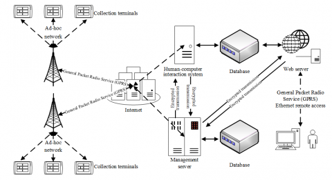
Figure 1 gives the constructed system structure. The system has four 4 main parts: heating temperature collection terminal group, human-computer interaction system, room temperature management server, and Web server. The heating temperature collection terminal group contains collection terminals and heat meter nodes. The human-computer interaction system is responsible for forwarding remote control commands of administrators or users, and analyzing the heat supply temperature data. The management server is in charge of processing indoor temperature adjustment signals, managing the heating metering and charging of individual households, early alarming of abnormal temperature, and processing relevant data. The Web server offers a data interface for the remote access of administrators or users. Figure 2 shows a diagram of the system functions. Administrators and individual household users must log into the system before performing other operations.
Figure 1. System structure
Figure 2. Diagram of system functions
Figure 3. Structure of the central heating system in residential buildings
Based on a few principles of separate room temperature control, easy construction, fair and reasonable charging, and effective alleviation of vertical thermal imbalance, this paper updated the individual household-based heating metering method of central heating in residential buildings, and reformed the cross-over pipes of the traditional vertical single-pipe uniflow heating system. Figure 3 gives the structure of the reformed structure. The new system adds a bypass pipe and an on-off controller to the water inlet pipe of radiator in each household, and adds a temperature controller to control the on-off valve in each room. In this system, the heat sharing unit of the heating metering of residential buildings is determined to be the heat supply loop of each household, the values of the heat sharing unit and the total heat supply volume of an entire building could be estimated based on the heating area of radiator in each household, the indoor temperature, the temperature of the return water of bypass pipe, and the on-off time ratio of the on-off controller.
To ensure a comfortable indoor heating effect inside the residential buildings, it’s necessary to well adjust the hydraulic balance of the central heating system. Assuming: ΔW and R respectively represent the pressure loss and resistance of the heat supply pipe section, F represents the flow; since the turbulent transition zone is a normal state of hot water flow in the heat supply pipe section, under actual working conditions, the hydraulics of the pipe sections can be calculated based on Formula 1:
$\Delta W=R{{F}^{2}}$ (1)
Assuming: MR represents the total number of household radiators in the residential buildings of a community, in this paper, the sum of RIP,I (the parallel resistance of all household radiators and cross-over pipes in community residential buildings) and RP (the fixed resistance of public pipe sections) is defined as RT (the total resistance of the system), then there is:
${{R}_{T}}=\sum\limits_{i=1}^{{{M}_{R}}}{{{R}_{IP,i}}+{{R}_{P}}}$ (2)
Assuming: RS,I and RH,i respectively represent the resistance of cross-over pipe sections and the resistance of radiators, then RIP,i can be calculated using the formula below:
$\frac{1}{\sqrt{{{R}_{IP,i}}}}=\frac{1}{\sqrt{{{R}_{S,i}}}}+\frac{1}{\sqrt{{{R}_{H,i}}}}$ (3)
Assuming β represents the inflow coefficient, based on the principle of pressure balance in the parallel loop of heat supply pipe sections, an equation can be established as below:
${{R}_{S,i}}\times {{\left( F\times \left( 1-\beta \right) \right)}^{2}}={{R}_{H,i}}\times {{\left( F\times \beta \right)}^{2}}$ (4)
According to above formula, when the cross-over pipes are connected in parallel with the radiators, the values of the pressure at the joints are equal, by simplifying above formula we can get:
${{R}_{S,i}}={{R}_{H,i}}\times {{\left( \frac{1-\beta }{\beta } \right)}^{2}}$ (5)
Combining Formula 3 and Formula 5, there is:
$\begin{align}& {{R}_{IP,i}}=\frac{{{R}_{S,i}}\times {{R}_{H,i}}}{\left( \sqrt{{{R}_{S,i}}}+\sqrt{{{R}_{H,i}}} \right)}=\frac{{{R}_{S,i}}^{2}\times {{\left( \frac{1-\beta }{\beta } \right)}^{2}}}{{{\left( \sqrt{{{R}_{S,i}}}+\sqrt{{{R}_{H,i}}}\times \left( \frac{1-\beta }{\beta } \right) \right)}^{2}}} \\ & =\frac{{{R}_{S,i}}\times {{\left( \frac{1-\beta }{\beta } \right)}^{2}}}{{{\left( \frac{1}{\beta } \right)}^{2}}}={{R}_{S,i}}\times {{\left( 1-\beta \right)}^{2}} \\\end{align}$ (6)
For the central heating system of community residential buildings, if there’s no heat user operation in the system, namely the resistance of cross-over pipes is RS, then the total resistance of the system RT is:
${{R}_{T}}=\sum\limits_{i=1}^{{{M}_{R}}}{{{R}_{IP,i}}+{{R}_{P}}}={{M}_{R}}\times {{R}_{S}}\times {{\left( 1-\beta \right)}^{2}}+{{R}_{P}}$ (7)
If the on-off controller of the radiator group in a household is in the off state, the RIP,i at this time can be approximated as RS,i. Therefore, if the on-off controllers of N radiator groups in the central heating system are in the off state at the same time, then the RT at this time is:
$\begin{align} & {{R}_{T}}={{\sum\limits_{i=1}^{{{M}_{R}}}{{{R}_{IP,i}}+{{R}_{P}}=\left( {{M}_{R}}-N \right)\times {{R}_{S}}\times \left( 1-\beta \right)}}^{2}} \\ & +N\times {{R}_{S}}+{{R}_{P}} \\\end{align}$ (8)
Perform central heating renovation on a 6-floor old-fashioned residential building with 3 households on each floor, assuming the total of number household radiators is 6×3×6=108, the value of inlet coefficient β takes 0.35, then the total resistance of the renovated central heating system RT can be expressed as:
$\begin{align} & {{R}_{T}}=\sum\limits_{i=1}^{108}{{{R}_{IP,i}}+{{R}_{P}}=\left( 108-N \right)\times {{R}_{S}}\times 0.4225} \\ & +N\times {{R}_{S}}+{{R}_{P}}=\left( 45.63+0.5775N \right)\times {{R}_{S}}+{{R}_{P}} \\\end{align}$ (9)
Since for the traditional vertical single-pipe uniflow heating systems, the pressure difference change of the on/off states of the on-off controller is negligible, that is, let the pressure ΔWOP at the joint when cross-over pipe is in parallel with the radiator be a fixed value, then there is:
${{F}_{N}}={{F}_{0}}\times \sqrt{\frac{45.63{{R}_{S}}+{{R}_{P}}}{45.63{{R}_{S}}+{{R}_{P}}+0.5775N{{R}_{S}}}}$ (10)
After adjusted by the on-off controller in each household, the ratio of adjusted flow FN to the initial flow F0 is:
$\frac{{{F}_{N}}}{{{F}_{0}}}=\sqrt{\frac{45.63{{R}_{S}}+{{R}_{P}}}{45.63{{R}_{S}}+{{R}_{P}}+0.5775N{{R}_{S}}}}$ (11)
This study chose to analyze the monotonicity of Formula 12 to obtain more accurate change range of FN/F0. It’s defaulted that function g(RP) only contains one variable RP, take the partial derivative of g(RF) with respect to RP, then there is:
$\frac{\partial g\left( {{R}_{P}} \right)}{\partial {{R}_{P}}}=\frac{0.5775N{{R}_{S}}}{{{\left( 45.63{{R}_{S}}+{{R}_{P}}+0.5775N{{R}_{S}} \right)}^{2}}}>0$ (12)
Because g(RP) increases monotonically, when RP is greater than 0, equation g(Rp)>g(0) holds. Combining Formulas 11 and 12, we can get:
$\begin{align} & \frac{{{F}_{N}}}{{{F}_{0}}}=\sqrt{\frac{45.63{{R}_{S}}+{{R}_{P}}}{45.63{{R}_{S}}+{{R}_{P}}+0.5775N{{R}_{S}}}} \\ & >\sqrt{\frac{45.63{{R}_{S}}+{{R}_{P}}}{45.63{{R}_{S}}+0.5775N{{R}_{S}}}}=\sqrt{\frac{45.63}{45.63+0.5775N}} \\\end{align}$ (13)
Based on Formula 13, the change of hot water flow in the pipe sections of the central heating system after N radiators have been subject to on-off control in groups could be calculated. For a newly built residential building with MR radiators, if the inlet coefficient of the radiator is β, then there is:
$\begin{align} & \frac{{{F}_{N}}}{{{F}_{0}}}=\sqrt{\frac{{{\left( 1-\beta \right)}^{2}}\times {{M}_{R}}{{R}_{S}}}{{{\left( 1-\beta \right)}^{2}}\times {{M}_{R}}{{R}_{S}}+\left( 1-{{\left( 1-\beta \right)}^{2}} \right)\times N{{R}_{S}}}} \\ & =\sqrt{\frac{{{\left( 1-\beta \right)}^{2}}\times {{M}_{R}}}{{{\left( 1-\beta \right)}^{2}}\times {{M}_{R}}+\left( 1-{{\left( 1-\beta \right)}^{2}} \right)\times N}} \\\end{align}$ (14)
Above formula suggests that, the impact of β on the hot water flow change in the pipe sections of the central heating system is quite obvious; when the β value is fixed and there’re changes in the hot water flow of pipe sections caused by the on-off controller, the size of the change value is related to N(the number of radiators participating in the adjustment) and MR(the total number of radiators in the residential building households of the community). If two buildings with different floor numbers, different household numbers on each floor, and same number of radiators in each household are compared, it could prove that the higher the floor, the less obvious the change in the hot water flow in the pipe sections. If the radiator on-off valves of all households in the heating system are in an off state, namely N is equal to MR, then there is:
$\frac{{{F}_{N}}}{{{F}_{0}}}>1-\beta $ (15)
That is, when the fixed resistance RP of the public pipe sections is ignored and β is equal to 0.35, the maximum change of the hot water flow in the pipe sections of the heating system is less than 35%. If the fixed resistance RP of the public pipe sections is considered and RP is greater than RS, the relevant parameters can be calculated according to the above formula.
After the cross-over pipe renovation, in the central heating system of community residential buildings, the size of the heat dissipation volume of radiators will change with the hot water flow in pipe sections. Assuming S represents the heat dissipation area of the radiator, P represents the heat dissipation volume of the radiator, Ψ represents the heat transfer coefficient of the radiator, hAV represents the average temperature of hot water in the radiator, hIN represents the indoor temperature of the household, then, the radiator heat dissipation formula can be deduced by the inversely solving the formula of the heat dissipation area of the radiator:
$S=\frac{P}{\Psi \left( {{h}_{AV}}-{{h}_{IN}} \right)}$ (16)
where, the value of hAV takes the arithmetic mean of hIN and the hWS the temperature of the hot water provided by the radiator:
${{h}_{AV}}=\left( {{h}_{WS}}+{{h}_{IN}} \right)/2$ (17)
The heat dissipation volume of the radiator is:
$P=\Psi S\left( {{h}_{AV}}-{{h}_{IN}} \right)$ (18)
The material, structure, casting condition, and using condition of the radiator are direct influencing factors of the heat transfer coefficient of the radiator. In this study, the numerical simulation method was used to characterize the degree of such direct influence, and the size of the heat transfer coefficient was determined via experiments. Assuming r and e represent two characteristic coefficients of the radiator, then there is:
$\Psi =r{{\left( \Delta h \right)}^{e}}=r{{\left( {{h}_{AV}}-{{h}_{IN}} \right)}^{e}}$ (19)
Assuming ∆h represents the logarithmic average temperature difference of the heat dissipation of the radiator, ∆h* represents the arithmetic average temperature difference, hBW represents the temperature of the return water of the radiator, hWS* represents the inlet water temperature of the radiator in the next household, then the heat dissipation volume of the radiator can be expressed as:
$P=r{{\left( \Delta h \right)}^{e}}=rS{{\left( {{h}_{AV}}-{{h}_{IN}} \right)}^{e+1}}$ (20)
∆h can be calculated by Formula 21:
$\Delta h=\frac{{{h}_{WS}}+{{h}_{BW}}}{2}-{{h}_{IN}}$ (21)
hBW can be calculated by Formula 22:
${{h}_{BW}}={{h}_{WS}}-\frac{{{h}_{WS}}+h_{WS}^{*}}{\beta }$ (22)
Formula 23 gives the relationship between the flow of hot water passing through the radiator and the heat dissipation volume of the radiator:
${P}'=1.157F\left( {{h}_{WS}}-{{h}_{BW}} \right)$ (23)
When the radiators in each household are all in a stable operating state, it can be considered that the heat volume dissipated by the hot water flowing through the radiator to the heating area of the radiator is equal to the heat dissipation volume of the radiator itself, that is P'=P.
When sharing the heat supplied by the central heating system of community residential buildings, theoretically, the supply heat volume is evenly distributed to each household. For the calculation of the heat consumption of each household, namely the unit heat load of heating design, it can be obtained by multiplying pHE (the heat index of heating area of the community residential buildings) by D(the floor area of each household):
${{P}_{HE}}={{p}_{HE}}D$ (24)
Under the condition that the system supplies heat stably, the heat loss in the heat supply process is ignored, then it’s considered that the unit heat load is equal to the heat volume supplied by the radiator in each household. Combining Formulas 20 and 24, there is:
$\frac{S}{D}=\frac{{{P}_{HE}}}{r{{\left( {{h}_{AV}}-{{h}_{IN}} \right)}^{e+1}}}$ (25)
If the residential buildings in the community have the same radiator model and installation method, then it could be considered that the values of the characteristic coefficients r and e of the radiator are fixed. Under the condition that the system supplies heat stably, approximately, it could be considered that the indoor heating area is proportional to the radiator installation area of the region, assuming there’re two radiators a and b, then the ratio of their indoor heating areas is:
$\frac{{{S}_{a}}}{{{S}_{b}}}\approx \frac{{{D}_{a}}}{{{D}_{b}}}$ (26)
Combining Formulas 20 and 24, then the ratio of heat dissipation volumes of a and b is:
$\begin{align} & \frac{{{P}_{a}}}{{{P}_{b}}}=\frac{r{{S}_{a}}{{\left( {{h}_{a,AV}}-{{h}_{a,IN}} \right)}^{1+e}}\times {{\delta }_{a}}}{r{{S}_{b}}{{\left( {{h}_{b,AV}}-{{h}_{b,IN}} \right)}^{1+e}}\times {{\delta }_{b}}} \\ & \approx \frac{{{D}_{a}}{{\left( {{h}_{a,AV}}-{{h}_{a,IN}} \right)}^{1+e}}\times {{\delta }_{a}}}{{{D}_{b}}{{\left( {{h}_{b,AV}}-{{h}_{b,IN}} \right)}^{1+e}}\times {{\delta }_{b}}} \\\end{align}$ (27)
According to above formula, the power of the average temperature difference of the radiator and the heating area of the radiator together determine the heat dissipation volume of the radiator, and it shows a proportional relationship, that is:
$P\propto D{{\left( {{h}_{AV}}-{{h}_{IN}} \right)}^{e+1}}\times \delta $ (28)
In this paper, the product of the power of the average temperature difference of the radiator and the heating area of the radiator is taken as the characteristic value ω of the radiator:
$\omega =D{{\left( {{h}_{AV}}-{{h}_{IN}} \right)}^{1+e}}\times \delta $ (29)
Assuming there are m households in the community residential buildings, and each household has A radiators, then the heat sharing ratio coefficient of the j-th radiator of the i-th household can be calculated by Formula 30:
${{\sigma }_{ij}}=\frac{{{\omega }_{ij}}}{\sum\limits_{i=1}^{m}{\sum\limits_{j=1}^{A}{{{\omega }_{ij}}}}}$ (30)
Formula 31 gives the calculation formula of the heat sharing ratio coefficient of the i-th household:
${{\sigma }_{i}}=\sum\limits_{j=1}^{A}{{{\sigma }_{ij}}}$ (31)
For households in a same central heating system, the sum of their heat sharing ratio coefficients is equal to 1:
$\sum\limits_{i=1}^{m}{{{\sigma }_{i}}}=1$ (32)
Therefore, the distributed heat volume of the j-th radiator of the i-th household can be calculated by Formula 33:
${{P}_{ij}}={{\sigma }_{ij}}{{P}_{T}}$ (33)
Withing the sharing cycle, the heat volume shared by the i-th household can be calculated by Formula 34:
${{P}_{i}}=\sum\limits_{j=1}^{A}{{{P}_{ij}}}$ (34).
6.1 In case of normal operation
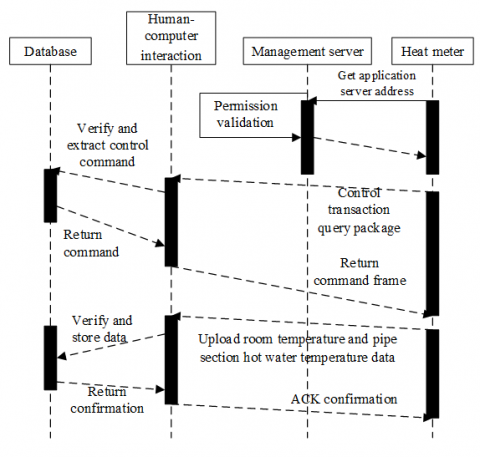
Figure 4. The communication process between the heat meter and the metering and charging management system
Figure 4 shows the communication process between the heat meter and the metering and charging management system. As can be seen from the figure, the heat meter node acts as the link between the heating household node and the metering and charging management server, it is responsible for collecting the heat consumption of each heating household in all residential buildings in the community, and then transmitting the data to the human-computer interaction system and the database for processing and storage. By the end of each data collection cycle, the central heating system performs one time heat sharing on all heat meters in each pipe section in the system. Assuming NC represents the serial number of the collection and sharing operation each time, Pi,NC and σij,NC represent the heat volume obtained by the i-th household in the NC-th heat distribution and the corresponding ratio coefficient, ωij,NC represents the corresponding characteristic value of the heat sharing, PT,NC and PT,NC-1 represent the heat stored in the heat meters of each pipe section in the system after the NC-th and the NC-1-th data collection, then, the heat distributed to the i-th household in the interval between the NC-th and the NC-1-th data collection is:
${{P}_{i,{{N}_{C}}}}=\left( {{P}_{T,{{N}_{C}}}}-{{P}_{T,{{N}_{C}}-1}} \right)\cdot {{\sigma }_{i,{{N}_{C}}}}$ (35)
Assuming k is the serial number of the radiator participating in the NC-th heat sharing, then the heat sharing ratio coefficient of the i-th household in the NC-th heat distribution is:
${{\sigma }_{i,{{N}_{C}}}}=\frac{\sum\limits_{j=1}^{A}{{{\omega }_{ij,{{N}_{C}}}}}}{\sum\limits_{k=1}^{m}{\sum\limits_{j=1}^{A}{{{\omega }_{ij,{{N}_{C}}}}}}}$ (36)
Assuming a heating period contains NT data collection cycles, then within the heating period, the total heat volume Pi,T shared by the i-th household is:
${{P}_{i,T}}=\sum\limits_{{{N}_{C}}=1}^{{{N}_{T}}}{{{P}_{i,{{N}_{C}}}}}$ (37)
6.2 In case of on-off heating adjustment of individual household radiator
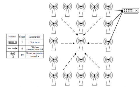
In the case that there’s on-off heating adjustment of radiator in individual household with in a certain data collection cycle U, this study set a sub-cycle O within U to complete the data collection and heat sharing of each pipe section in the system, and the sub-cycle O is determined by the opening times of the on-off valve. Figure 5 gives the communication link between the collection terminal and the heat meters. In view of this situation, the certain collection cycle needs to accept the collected and shared data information from sub-cycle O and other sub-cycles. Assuming MC represents the serial number of collection and sharing within sub-cycle O; Pi,MC and Pi,MC-1 represent the heat volume obtained by the i-th household in the MC-th and in the MC-1-th heat distribution; PT,MC represents the heat volume stored by the heat meters of each pipe section in the system in the MC-th heat distribution; σij,MC and ωij,MC represent the heat sharing ratio coefficient and the characteristic value of the i-th household in the MC-th heat distribution, then the heat distributed to the i-th household in the interval between the MC-th collection and the MC-1-th collection is:
${{P}_{i,{{M}_{C}}}}=\left( {{P}_{T,{{M}_{C}}}}-{{P}_{T,{{M}_{C}}-1}} \right)\cdot {{\sigma }_{i,{{M}_{C}}}}$ (38)
Assuming l represents the serial number of the radiator participating in the MC-th heat sharing, then the ratio coefficient of the i-th household in the MC-th heat distribution is:
${{\sigma }_{i,{{M}_{C}}}}=\frac{\sum\limits_{j=1}^{A}{{{\omega }_{ij,{{M}_{C}}}}}}{\sum\limits_{l=1}^{m}{\sum\limits_{j=1}^{A}{{{\omega }_{ij,{{M}_{C}}}}}}}$ (39)
Figure 5. Communication link between the collection terminal and the heat meters
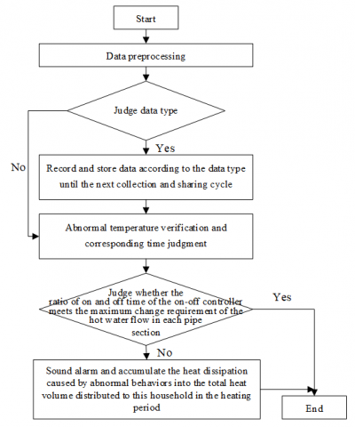
Figure 6. Abnormal temperature processing and heating metering process
Assuming the sub-cycle O contains MT data collection cycles, then, within the sub-cycle O, the accumulated shared heat can be calculated by Formula 40:
${{P}_{i,O}}=\sum\limits_{{{M}_{C}}=1}^{{{M}_{T}}}{{{P}_{i,{{M}_{C}}}}}$ (40)
Assuming PU,V represents the accumulated shared heat in collection cycle U except for sub-cycle O, then during the heating period, the total shared heat volume PT of the i-th household is:
${{P}_{T}}=\sum\limits_{U=1}^{{{N}_{T}}}{{{P}_{U,V}}}$ (41)
Under actual heating conditions, if there isn’t well-functioned monitoring equipment or reasonable monitoring method, the loss of indoor heat caused by sensor damage or continuous opening of windows might result in increased shared heat volume of other heating households within the same building, and the heating metering method would become unfair. Therefore, in view of such abnormal heat consumption behaviors, this study designed an alarming and metering process for the abnormal temperature detection, as shown in Figure 6. This study accumulated the heat dissipation caused by abnormal behaviors into the total heat volume shared by this household during the heating period to ensure the balance of heat sharing of all households.
For the heating system of traditional residential buildings after cross-over pipe renovation, the flow of hot water entering the radiator of each household is reduced, which leads to certain changes in the performance of the radiator. In order to figure out the influence of the inlet and return water temperature difference of the heating system on the performance of the radiator, this paper designed different inlet and return water temperature difference (5℃-45℃) conditions, and the changes of the heat dissipation performance of the radiator are plotted as the curves shown in Figure 7. As can be seen in the figure, when the inlet and return water temperature difference is between [5℃,15℃], the change of hot water flow is greater and the heat dissipation efficiency of the radiator is higher. When the inlet and return water temperature difference reaches 25℃ or higher, the change of hot water flow is smoother and the heat dissipation efficiency of the radiator is lower. Therefore, the household-based heating metering and charging management system designed in this study needs to operate under conditions with smaller inlet and return water temperature difference to ensure that each household could obtain ideal shared heat volume.
Figure 7. Relationship between heat dissipation volume and hot water flow under different design temperature differences
Figure 8 shows the relationship between the ratio of hot water flow before and after on-off adjustment and the number of radiator groups, as can be seen in the figure, the ratio of hot water flow before and after on-off adjustment decreases linearly with the increase of the number of radiator groups set in the heating system, and this conclusion is consistent with the actual situations.
Figure 9 shows the relationship between the hot water flow and the outdoor temperature, for the heating system of the residential buildings in a same community, the flow of supplied hot water also shows linear relationship with the outdoor temperature.
Table 1 shows the changes in the temperature and flow of primary and secondary inlet and return water and the outdoor temperature. When designing the radiator in the heating system of residential buildings, generally, the inlet and return water temperature values are set to 80℃ and 55℃, and ensure that the effective heating area of the radiator has a margin of 20%-30%.
Figure 10 gives the hourly change of hot water flow of the constructed heating system from 2017 to 2020. According to the figure, for the households in the buildings, the heating demands at night hours and during holidays were lower, the hot water flow for per unit indoor area dropped to about 75% of that of day hours, reaching 4.8m3/(h·m2), and the primary heat volume reached 36.47 W/m2. The primary hot water flow for per unit indoor area on work days was 1.52 times that of night hours and holidays, which was 7.52m3/(h·m2). The primary heat volume was 1.46 times that of night hours and holidays, which was 47.51W/m2.
Improvements were made based on the heat sharing and on-off adjustment scheme proposed in this paper, with 5 work days as an example, the reduction rates of primary hot water flow and primary heat volume for per unit indoor area were respectively 14.28% and 13.19%, indicating that the energy-saving effect was obvious.
Figure 8. Relationship between ratio of hot water flow before and after on-off adjustment and the number of radiator groups
Figure 9. Relationship between the flow of supplied hot water and the outdoor temperature
Table 1. Changes in the temperature and flow of primary and secondary inlet and return water and the outdoor temperature
|
Outdoor temperature (℃) |
6 |
5 |
4 |
3 |
2 |
1 |
0 |
|
Relative heat load |
0.4712 |
0.5223 |
0.5567 |
0.5235 |
0.6314 |
0.6312 |
0.6635 |
|
Primary T1g/℃ |
68.37 |
73.42 |
73.56 |
81.35 |
82.37 |
83.62 |
84.55 |
|
Primary T1h/℃ |
41.62 |
43.54 |
44.13 |
45.86 |
47.58 |
48.73 |
49.31 |
|
Secondary T1g/℃ |
47.57 |
49.51 |
52.38 |
53.47 |
55.67 |
56.49 |
57.31 |
|
Secondary T1h/℃ |
34.18 |
35.57 |
38.62 |
37.39 |
39.62 |
40.81 |
41.92 |
|
Outdoor temperature (℃) |
-1 |
-2 |
-3 |
-4 |
-5 |
-6 |
|
|
Relative heat load |
0.7209 |
0.7131 |
0.7358 |
0.7437 |
0.7612 |
0.7754 |
|
|
Primary Tg |
86.19 |
87.35 |
91.61 |
92.76 |
95.73 |
97.84 |
|
|
Primary Th |
50.06 |
50.83 |
50.95 |
51.37 |
52.19 |
53.82 |
|
|
Secondary t1 |
63.52 |
65.74 |
67.52 |
68.15 |
69.34 |
75.21 |
|
|
Secondary t2 |
42.82 |
45.25 |
46.38 |
48.98 |
49.47 |
50.33 |
|
Figure 10. Hourly change of hot water flow
This study designed a household-based heating metering and charging management system for central heating system in community residential buildings. At first, this paper constructed the structure of the system and drew a diagram of system functions. Then, it analyzed the hydraulic characteristics of the heating system and the influence on the heat dissipation volume of the radiator, and established a heating metering and heat distribution model; after that, this paper designed a scheme for the heating metering and heat sharing in cases of normal operation and on-off heating adjustment of individual household radiator. Moreover, experiments gave the relationship between the ratio of hot water flow before and after on-off adjustment and the number of radiator groups, and the relationship between the heat dissipation volume and hot water flow under the conditions of different design temperature difference, and verified the linear relationship between relevant parameters. At last, this paper also gave the hourly change of hot water flow of the constructed heating system from 2017 to 2020, and the scheme for heat sharing and on-off adjustment proposed in this paper had been proved to have obvious energy-saving effect.
[1] Tao, Y., Teng, C., Musho, T.D., van de Burgt, L., Lochner, E., Heller, W.T., Stiegman, A.E. (2021). Direct measurement of the selective microwave-induced heating of agglomerates of dipolar molecules: the origin of and parameters controlling a microwave specific superheating effect. The Journal of Physical Chemistry B, 125(8): 2146-2156. https://doi.org/10.1021/acs.jpcb.0c10291
[2] Oikawa, D., Iwatsuka, S., Sugiura, T., Andoh, H., Tsukamoto, T. (2016). Heating effect of mesa-type intrinsic josephson junction stacks using pulse current measurement. Physics Procedia, 81: 137-140. https://doi.org/10.1016/j.phpro.2016.04.028
[3] Kikuchi, T., Hayashi, R., Takahashi, T., Tamura, F., Takahashi, K., Sasaki, T., Harada, N. (2016). Numerical simulation on measurement of optical and thermal properties for warm dense matter generated by isochoric heating with pulsed power discharge device. In Journal of Physics: Conference Series, 688(1): 012047. https://doi.org/10.1088/1742-6596/688/1/012047
[4] Yoshikawa, N., Inoue, N., Watanabe, T., Komarov, S. (2018). Permittivity and electric conductivity measurement and microwave heating behavior of Mo/Cordierite composite materials. In 2018 Asia-Pacific Microwave Conference (APMC), pp. 1136-1138. https://doi.org/10.23919/APMC.2018.8617130
[5] Aida-zade, K.R., Hashimov, V.A. (2018). Optimization of measurement points positioning in a border control synthesis problem for the process of heating a rod. Automation and Remote Control, 79(9): 1643-1660. https://doi.org/10.1134/S0005117918090096
[6] Serrano, J., Acero, J., Alonso, R., Carretero, C., Lope, I., Burdío, J.M. (2016). Design and implementation of a test-bench for efficiency measurement of domestic induction heating appliances. Energies, 9(8): 636. https://doi.org/10.3390/en9080636
[7] Vidana Gamage, D.N., Vasava, H.B., Strachan, I.B., Adamchuk, V.I., Biswas, A. (2021). Comparison of heating strategies on soil water measurement using actively heated fiber optics on contrasting textured soils. Sensors, 21(3): 962. https://doi.org/10.3390/s21030962
[8] Tofighi, M.R., Attaluri, A. (2020). Closed-loop pulse-width modulation microwave heating with infrared temperature control for perfusion measurement. IEEE Transactions on Instrumentation and Measurement, 70: 1-7. https://doi.org/10.1109/TIM.2020.3019617
[9] Stanfield, A.D., Manara, D., Robba, D., Hilmas, G.E., Fahrenholtz, W.G. (2021). Measurement of the melting temperature of ZrB2 as determined by laser heating and spectrometric analysis. Journal of the American Ceramic Society, 104(6): 2780-2787. https://doi.org/10.1111/jace.17634
[10] Tofighi, M.R., Pardeshi, J.R., Maicke, B.A. (2016). Microwave system and methods for combined heating and radiometric sensing for blood perfusion measurement of tissue. In 2016 IEEE MTT-S International Microwave Symposium (IMS), pp. 1-4. https://doi.org/10.1109/MWSYM.2016.7540197
[11] Casasnovas, J., Anantheswaran, R.C. (2016). Dynamic measurement of starch granule swelling during microwave heating. Carbohydrate Polymers, 151: 1052-1057. https://doi.org/10.1016/j.carbpol.2016.06.065
[12] Alqahtani, M., Buijs, A., Day, S.E. (2020). Experimental measurement and Monte Carlo code simulation of the gamma heating at different irradiation sites in a nuclear research reactor. Nuclear Engineering and Design, 364: 110690. https://doi.org/10.1016/j.nucengdes.2020.110690
[13] Kazemi, M., Khodaiyan, F., Labbafi, M., Hosseini, S.S. (2020). Ultrasonic and heating extraction of pistachio by-product pectin: physicochemical, structural characterization and functional measurement. Journal of Food Measurement and Characterization, 14(2): 679-693. https://doi.org/10.1007/s11694-019-00315-0
[14] Choi, G.H., Kim, D.H., Shin, C.H., Kim, J.Y., Kim, B.J. (2020). In-situ deformation measurement of Zircaloy-4 cladding tube under various transient heating conditions using optical image analysis. Nuclear Engineering and Design, 370: 110859. https://doi.org/10.1016/j.nucengdes.2020.110859
[15] Hettler, S., Sebastian, D., Pelaez-Fernandez, M., Benito, A.M., Maser, W.K., Arenal, R. (2021). In-situ reduction by Joule heating and measurement of electrical conductivity of graphene oxide in a transmission electron microscope. 2D Materials, 8(3): 031001. https://doi.org/10.1088/2053-1583/abedc9
[16] Yoshino, T., Wang, R., Gomi, H., Mori, Y. (2020). Measurement of the Seebeck coefficient under high pressure by dual heating. Review of Scientific Instruments, 91(3): 035115. https://doi.org/10.1063/1.5143525
[17] Francisco Jr, R.W., Oliveira, A.A.M. (2020). Measurement of the adiabatic flame speed and overall activation energy of a methane enriched H2/CO/CO2/N2 low heating value mixture. International Journal of Hydrogen Energy, 45(53): 29533-29545. https://doi.org/10.1016/j.ijhydene.2020.07.200
[18] Han, V.C., Kakuta, N. (2020). Near-infrared measurement of water temperature near micro-magnetic particle layer in a fluidic channel under induction heating. Experimental Thermal and Fluid Science, 115: 110087. https://doi.org/10.1016/j.expthermflusci.2020.110087
[19] Casey, J.G., Ortega, J., Coffey, E., Hannigan, M. (2018). Low-cost measurement techniques to characterize the influence of home heating fuel on carbon monoxide in Navajo homes. Science of the Total Environment, 625: 608-618. https://doi.org/10.1016/j.scitotenv.2017.12.312
[20] Filippini, E., Marini, I., Ongari, M., Pedretti, E. (2018). District heating leakage measurement: Development of methods. Energy Procedia, 149: 297-306. https://doi.org/10.1016/j.egypro.2018.08.193
[21] Gerlach, O., Lechler, A., Verl, A. (2018). Measurement of the controlled variable during heating of Ti6Al4V for thixoforging. Materials Research Express, 5(2): 026508. https://doi.org/10.1088/2053-1591/aaab0e
[22] Carcreff, H., Salmon, L., Lepeltier, V., Guyot, J.M., Bouard, E. (2018). Simultaneous measurements of nuclear heating and thermal neutron flux obtained with the CALMOS-2 measurement device inside the OSIRIS reactor. In Reactor Dosimetry: 16th International Symposium. ASTM International, pp. 380-391. https://doi.org/10.1520/STP160820170049
[23] Oskolkov, A., Bezukladnikov, I., Trushnikov, D. (2021). Indirect temperature measurement in high frequency heating systems. Sensors, 21(7): 2561. https://doi.org/10.3390/s21072561
[24] Suzuki, T., Namiki, J., Hasemi, Y., Takase, R., Kamikawa, D., Yasui, N., Kaku, C. (2020). Measurement of distribution of temperature and moisture content within wooden plate under steady heating and numerical reproduction with heat and water transfer analysis. Journal of Environmental Engineering (Japan), 85(778): 891-901.