Zygmunt Lipnicki | Adam W. Bydałek* | Tomasz Małolepszy
© 2021 IIETA. This article is published by IIETA and is licensed under the CC BY 4.0 license (http://creativecommons.org/licenses/by/4.0/).
OPEN ACCESS
In this paper we are investigating theoretically the process of solidification of a liquid alloy in the space. A simplified quasi steady-state analytical model for the solidification process is used. This model describes the phase change phenomenon with the two-phase solidification front, so the two-phase layer between the liquidus and the solidus is analyzed with a solidification liquid being overheated above the solidification temperature. The solution of the problem can be reduced to the solution of a system of differential equations, which has been solved numerically. From this model, an influence of various dimensionless parameters on the solidification process can be clearly seen. The obtained numerical results are presented in graphical figure. In addition, the variable coefficient of a heat transfer on the surface of the solidification front during the solidification process is also calculated.
development of a simple analytical model, heat transfer, phase change, two-phase layer
One of the stages during a manufacturing process of an alloy is its solidification [1-12]. A very interesting and important publication on an alloy solidification is the work of Beckermann and Viskanta [1] from 1993, where the mathematical modeling of mass, momentum, heat and transport phenomena that accompany the alloy solidification is reviewed. This article focuses mainly on the role of the two-phase layer on the solidification front in the casting of metal alloys. As the two-phase layer at the front plays a particularly important role in the solidification process, there are many studies in the professional literature related to the modeling of solidification process that includes the two-phase zone [6, 8, 10-12]. However, there are only a few studies in the literature that describe the macroscopic process of alloying in a simple manner [5, 7, 11], which is one of the goals of this work.
The important aim of the work is, however, to determine, based on the theoretical foundations, the heat flow between the casting mold and the metal that solidifies in it. A simplified quasi-stationary analytical model of the crystallization process has been proposed. The phenomenon of the phase change with a two-stage solidification front, which takes into account the areas of columnar and equiaxial crystals, has been also described. In this model, the two-phase layer between liquidus and solidus is analyzed. To adjust the model to real conditions, overheating of the metal above the liquidus temperature is included. Furthermore, the variable heat transfer coefficient on the surface of the solidification front during the solidification process is determined.
To our best knowledge, there are no studies in the scientific literature that theoretically analyze the solidification process in the two-phase zone. The distribution of heat sources and temperature in this zone in time and space are particularly interesting and important. The mentioned parameters significantly influence the development and the progress of the solidification process in this two-phase space. A novelty in the presented work is the analytical determination of the development of the solidification front: its position and velocity in the solidifying alloy on the basis of Stefan equations, and in particular the determination of the temperature distribution in a two-phase space using the classical Poisson equations. This publication presents an example of the solidification process in the continuous casting of a brass alloy.
The article discusses the problem of solidification of alloys with particular emphasis on the two-stage crystallization front. The research part presents the simulation results of the two-stage front of the crystallization setting in continuous casting. Finally, conclusions were built, indicating further research directions.
There are many solutions, both analytical and numerical, in the literature relating to the modeling of crystallization processes [1-12]. So far, however, none has fully described these nonlinear and non-stationary phenomena.
The process of solidification of the metal alloy in this work is described analytically with quasi-stationary heat flow equations using the Stefan solidification model. In this work, a numerical analytical model of solidification of a metal alloy (brass) was solved. The time and velocity of its solidification were determined. In the two-phase zone, the quasi-stationary solidification process with heat sources was solved using the Poisson differential equation. The calculation results are presented in the form of graphs and tables.
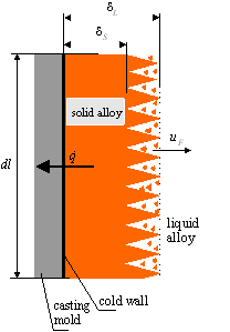
The diagram of solidification of the cooled metal with the participation of a crystallizer (referred further as the cold wall) and the theoretical description of this model are presented in Figure 1a and Figure 1b, respectively.
(a)
(b)
Figure 1. (a) Diagram of the alloy solidification front, (b) Temperature distribution in the solidifying alloy
In the model it was assumed that the liquid alloy with the temperature $T_{C}$ contacts with the cold wall with the surface temperature $T_{W} .$ Based on the results of research in the literature $[1,13]$ and own structural analysis, it was found that the emergent alloy solidification front is not sharp (Figure 1 a). It was further assumed that on the surface of the solidified layer with a layer thickness of $\delta_{S}$ there is the solidus temperature $T_{S}$ and at a distance of $\delta_{L}$ from the wall surface is the liquidus surface with the temperature $T_{L}$, which is slightly higher than the solidus temperature $T_{S}$. The wall surface temperature $T_{W}$ is lower than the solidus temperature $T_{S}$, liquidus $T_{L}$ and the temperature of the liquid alloy $T_{C}$, so the temperature distribution is as follows: $T_{W}<T_{S}<T_{L}<T_{C}$ (Figure $1 \mathrm{~b}$ ). The phenomenon of heat transfer from the liquid alloy to the solidifying alloy occurs on the liquidus surface. The direction of heat flow $\dot{q}$ is opposite to the $x$ -axis that defines the direction of the solidification area of the alloy from the crystallizer surface). The whole solidification process is considered in a two-phase layer (liquid and solid), in which the heat of crystallization $L$ is additionally generated.
The modeled phenomenon of quasi-stationary solidification of the liquid alloy is described by a simplified heat balance equation:
$h_{C O N}\left(\bar{T}-T_{W}\right)=\frac{k_{S}}{\delta_{s}}\left(T_{s}-\bar{T}\right)=-\rho_{s} c_{s} \frac{d}{d t} \int_{0}^{\delta_{s}}(T-$$\bar{T}) d x+\dot{q}+h\left(\bar{T}_{C}-T_{L}\right)$, (1)
where the first expression defines the heat flux conducted through the contact layer, the second expression defines the heat flux conducted through the solidified alloy layer, the third expression defines the heat absorbed by the solidified alloy layer (i.e. heat of accumulation), the heat flux $\dot{q}$ expresses the heat generated as a result of solidification of the alloy in the two-phase layer and the last expression describes the heat transferred from the liquid alloy to the solidifying alloy.
2.1 Heat generated in the two-phase zone of the alloy
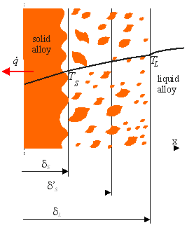
During the solidification of the alloy, a moving interfacial layer is formed on its forehead, which is bounded by the changing in the time surfaces of the solidus $\delta_{S}$ and the liquidus $\delta_{L}$ (Figure 2). Inside the layer between the liquidus and solidus surfaces $\delta_{S}<\delta_{S}^{\prime}<\delta_{L}$ there is a surface with the position coordinate $\delta_{S}^{\prime}$ and with the solid phase volume fraction $S .$
Figure 2. Element of the two-phase layer
The energy conservation equation in the two-phase zone was analyzed by Mochnacki and Suchy [13]. Based on their considerations, the following solidification analysis in this zone is given below. The heat of solidification (heat source) generated at time t anywhere inside the moving two-phase zone can be defined by the expression
$\rho_{S} L \frac{d \delta_{S}^{\prime}}{d t}$,
where $d \delta_{S}^{\prime} / d t$ is the solidification rate, $L$ is the latent solidification heat of the alloy and $\rho_{S}$ is the solidification layer density. The volume fraction of the solid $S$ in the two-phase layer depends on the location $x$. A hypothesis describing the solidification velocity distribution in the layer of the twophase zone $d \delta_{S}^{\prime} / d t$ as a function of the volume fraction $S$ of the solid phase in the layer was adopted. It was also assumed that the rate of the solidification inside the interfacial area depends linearly on the volume fraction of the solid phase $S$ :
$\frac{d \delta_{S}^{\prime}}{d t}=a S+b$, (2)
where a and b are constants.
Substituting the value of the parameter $S=1$ (no liquid metal- there is $100 \%$ of the solid phase) on the solidus surface and $S=0$ (no solid phase in the liquid metal) on the liquidus surface, the constants $a$ and $b$ can be determined and then Eq. (2) takes the following form:
$\frac{d \delta_{S}^{\prime}}{d t}=\left(\frac{d \delta_{S}}{d t}-\frac{d \delta_{L}}{d t}\right) S+\frac{d \delta_{L}}{d t} .$ (3)
Using Eq. (3), the total heat flux generated in the interphase space can be also determined:
$\dot{q}=\int_{0}^{1} \rho_{S} L \frac{d \delta_{S}^{\prime}}{d t} d S=\frac{1}{2} \rho_{S} L\left(\frac{d \delta_{S}}{d t}+\frac{d \delta_{L}}{d t}\right)$. (4)
The thickness of the space-traveling two-phase layer is small and, in general, it constantly changes during the solidification. The total heat flux generated in such a layer, with equal derivatives $\partial \delta_{S} / \partial t=\partial \delta_{L} / \partial t$ is hence equal to:
$\dot{q}=\rho_{S} L \frac{d \delta_{S}}{d t}$. (5)
2.2 Solidification heat balance equations for an alloy
The temperature distribution in the stationary overheated liquid alloy and the heat flux on the liquidus surface, based on the Fourier heat conduction law, are described by the equations:
$T_{C}=2 \frac{\bar{T}_{C}-T_{L}}{H-\delta_{L}}\left(x-\delta_{L}\right)+\frac{T_{L}\left(H+\delta_{L}\right)-2 \bar{T}_{C} \delta_{L}}{H-\delta_{L}}$, (6)
$\dot{q}=\left.k_{L} \frac{\partial T}{\partial x}\right|_{x=\delta_{L}}=2 k_{L} \frac{\bar{T}_{C}-T_{L}}{H-\delta_{L}}$. (7)
By comparing the heat transferred and conducted on the liquidus surface.
$\dot{q}=h\left(\bar{T}_{C}-T_{L}\right)=2 \frac{k_{L}}{H-\delta_{L}}\left(\bar{T}_{C}-T_{L}\right)$,
The heat transfer coefficient h can be obtained as follows:
$h=2 \frac{k_{L}}{H-\delta_{L}}$. (8)
The average temperature of the liquid alloy and the change in heat capacity in the variable liquid volume (i.e. $H-\delta_{L}$) are described by the equations:
$\bar{T}_{C}-T_{L}=\frac{\int_{\delta_{L}}^{H}\left(T_{C}-T_{L}\right) d x}{H-\delta_{L}}$, (9)
$\rho_{L} c_{L} \frac{d}{d t} \int_{\delta_{L}}^{H}\left(T_{C}-T_{L}\right) d x$$=\rho_{L} c_{L} \frac{d}{d t}\left[\left(\bar{T}_{C}-T_{L}\right)\left(H-\delta_{L}\right)\right]$. (10)
From the heat balance equation for a liquid alloy (the heat acquired from the liquid metal is equal to the accumulation heat of the liquid alloy), it follows that,
$h\left(\bar{T}_{C}-T_{L}\right)=-\rho_{L} c_{L} \frac{d}{d t}\left[\left(\bar{T}_{C}-T_{L}\right)\left(H-\delta_{L}\right)\right]$. (11)
Suitable transformations of Eqns. (1) and (11) lead to a system of differential equations, which in dimensionless coordinates take the form:
$\frac{B i_{C O N}}{1+\widetilde{\delta} B i_{C O N}}+\frac{1}{2} \frac{d \widetilde{\delta}}{d \tau}\left(\operatorname{Ste} \tilde{\delta} \frac{B i_{C O N}}{1+\widehat{\delta} B i_{C O N}}-2\right)=2 \frac{k}{1-\tilde{\Delta}-\widehat{\delta}} B \bar{\theta}_{C}$, (12)
$2 \frac{\tilde{a}}{1-\tilde{\Delta}-\tilde{\delta}} \bar{\theta}_{C}=-$ Ste $\frac{d}{d \tau}\left[\bar{\theta}_{C}(1-\tilde{\Delta}-\tilde{\delta})\right]$. (13)
In addition, system of Eqns. (12)-(13) satisfies for $\tau=0$ the initial conditions:
$\tilde{\delta}=0$ and $\bar{\theta}_{C}=1$. (14)
Variables and parameters used in problem (12)-(14) are equal to:
$\tilde{\delta}=\frac{\delta_{s}}{H}, \tau=\operatorname{Ste} \cdot F o, \bar{\theta}_{C}=\frac{\bar{T}_{C}-T_{L}}{T_{C 0}-T_{L}}, \tilde{\Delta}=\frac{\Delta}{H}$
$\tilde{k}=\frac{k_{L}}{k_{S}}, \tilde{a}=\frac{a_{L}}{a_{S}}, B=\frac{T_{C 0}-T_{L}}{T_{S}-T_{W}}, B i_{C O N}=\frac{h_{C O N} H}{k_{S}}$,
and they respectively denotes: dimensionless thickness of the solidified layer, dimensionless time, dimensionless mean overheating temperature of the liquid, dimensionless thickness of the interfacial layer, the ratio of thermal conductivities of the liquid alloy to the solidified layer, the ratio of the thermal conductivity of the liquid and the solidified layer, the heat diffusion ratio of the liquid and the solidified layer, the liquid overheating parameter and finally Biot number in the contact layer.
Moreover, Stefan number Ste, Fourier number Fo and thermal diffusivity coefficients aS and aL in Eqns. (11)-(12) are respectively given by:
Ste $=\frac{c_{S}\left(T_{S}-T_{W}\right)}{L}, F o=\frac{a_{S} t}{H^{2}}, a_{S}=\frac{k_{S}}{c_{S} \rho_{S}}, a_{L}=\frac{k_{L}}{c_{L} \rho_{L}}$.
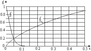
The non-linear system of differential equations (12)-(13) cannot be solved analytically, thus the use of numerical calculations is necessary. The complete solution of the system of equations, i.e. the determination of unknown functions: functions: $\delta(\tau), \bar{\theta}_{C}(\tau), \tilde{\Delta}(\tau)$ requires the creation of an additional constitutive relationship defining the thickness of the two-phase layer $\tilde{\Delta}(\tau)$, based on either the laws of physics or from experimental research, however, additional analysis is needed for this purpose. The numerical solution of problem (12)-(14), assuming a constant thickness of the two-phase layer (i.e. $\Delta=\delta_{L}-\delta_{S}=$ const $)$, is presented graphically in Figure 3.
Figure 3. Solidification of $\tilde{\Delta}=0.1, B=1.2$ and $B i_{C O N}=10$
Table 1 presents the main parameters of the solidifying alloy, which were used in numerical calculations of the solidified layer and the overheating temperature (see Figures 3 and 4).
Table 1. Parameters that characterize the solidification phenomenon of Zn10 brass, describing the actual solidification conditions for a cold flat wall with a temperature of TW=998℃
|
$\boldsymbol{T}_{L},{ }^{\circ} \mathrm{C}$ |
$\boldsymbol{T}_{S},{ }^{\circ} C$ |
$L, k J / k g$ |
$\boldsymbol{k}_{S}, W /(m K)$ |
$\boldsymbol{c}_{\boldsymbol{s}}, \mathrm{J} /(\mathrm{kgK})$ |
|
1,050 |
1,040 |
200 |
370 |
386 |
|
1,050 |
1,040 |
200 |
376 |
386 |
|
$\boldsymbol{\rho}_{\boldsymbol{S}}, \mathrm{kg} / \mathrm{m}^{3}$ |
$\tilde{\Delta}$ |
Ste |
$\boldsymbol{B} \boldsymbol{i}_{\boldsymbol{C O N}}$ |
B |
|
8,740 |
0.1 |
0.081 |
10 |
0 |
|
8,740 |
0.1 |
0.081 |
10 |
1.2 |
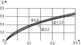
The influence of overheating parameter B on the Zn10 alloy is shown in Figure 4. The presented comparative results of the solidification process clearly suggest that the rate of solidification of the alloy strongly depends on the degree of overheating. As it increases, the alloy solidification velocity decreases.
Figure 4. Development of the solidified layer for Zn10 and $B i_{C O N}=10$ for overheating parameters B
Using the following model simplification in the nonlinear problem (12)-(14): no overheating of the liquid alloy (B=0), a simple differential equation for the thickness of the solidified layer $\widetilde{\delta}$ can be obtained.
$\frac{1}{2}\left(2 \frac{1+\tilde{\delta} B i_{C O N}}{B i_{C O N}}-S t e \tilde{\delta}\right) \frac{d \tilde{\delta}}{d \tau}=1$, (15)
which analytical solution is given by:
$\tilde{\delta}=-\frac{2}{B i_{C O N}(2-S t e)}+\sqrt{\frac{4}{B i_{C O N}^{2}(2-S t e)^{2}}+\frac{4}{2-S t e} \tau}$, (16)
Figure 5. Development of the solidified layer for B=0
Formula (16) allows to present in graphical form the development of the solidified layer and the speed of the solidification front of the alloy (see Figure 5). The graphs on this figure were made, for comparison purposes, for two different thermal resistances of the contact layer between the solidified layer and the cold wall surface that limit a wide range of thermal resistance: $B i_{C O N}=\infty$ (perfect thermal contact) and $B i_{C O N}=10$. As can be seen, the solidification rates of alloys for times $\tau>0.1$ are almost the same.
2.3 Temperature distribution in a two-phase layer
The phenomenon of alloy solidification under quasi-steady conditions in the two-phase zone (see Figure 2) can be described by the classical Poisson equation:
$\frac{\partial^{2} T}{\partial x^{2}}+\frac{\dot{q}_{V}(x)}{k_{m}}=0$, (17)
where the mean volume heat flux $\dot{q}_{V}$ (see Eq. (4)) is equal to:
$\dot{q}_{V}=\frac{\dot{q}}{\delta_{L}-\delta_{S}}=\frac{1}{2} \rho_{S} L \frac{\frac{d \delta_{S}}{d t}+\frac{d \delta_{L}}{d t}}{\delta_{L}-\delta_{S}}$. (18)
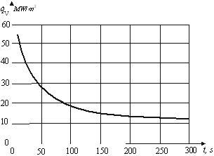
Figure 6. Dependence of the heat volume flow generated in the two-phase zone on the solidification time for Zn10 and $B i_{C O N}=\infty, B=0$, Ste $=0.081$
Table 2. Parameters of the two-phase zone during the solidification of the Zn10 alloy for selected times
|
$\boldsymbol{\tau}$ |
$\boldsymbol{t}, \boldsymbol{s}$ |
$\widetilde{\boldsymbol{\delta}}$ |
$\delta_{S}, m$ |
$\delta_{L}, m$ |
$d \widetilde{\delta} / d \tau$ |
$d \delta / d t, m / s$ |
$\dot{\boldsymbol{q}}_{V}, \boldsymbol{M W} / \boldsymbol{m}^{3}$ |
|
0.01 |
11.3 |
0.144 |
1.44·10-2 |
3.44·10-2 |
7.22 |
6.42·10-4 |
56.08 |
|
0.05 |
56.3 |
0.322 |
3.22·10-2 |
5.22·10-2 |
3.23 |
2.87·10-4 |
25.08 |
|
0.1 |
112.5 |
0.457 |
4.57·10-2 |
6.57·10-2 |
2.28 |
2.03·10-4 |
17.73 |
|
0.2 |
225 |
0.646 |
6.46·10-2 |
8.46·10-2 |
1.61 |
1.43·10-4 |
12.54 |
The graph of $\dot{q}_{V}$, treated as a function of t, is shown in Figure 6 whereas its some values along with the other parameters of two-phase layer related to the solidification of the Zn10 alloy are collected in Table 2.
Changes of the parameters during the solidification proces are showed in Table 2 . The results of the conducted theoretica research show that the solidification front $\delta(t)$ increases a time $t$ increases but with slower and slower velocity $d \delta / d t$ On the other hand, the volumetric heat flux $\dot{q}_{V}$ generated in the solidification process decreases with time.
The solution of the Poisson equation (17) in the space of the traveling two-phase layer, under the following conditions at the boundary of the layer:
$T=T_{S}$ for $x=\delta_{S}, T=T_{L}$ for $x=\delta_{L}$, (19)
is the temperature field expressed by a square polynomial depending on the location in the layer $\delta_{S}<x<\delta_{L}$, i.e.
$T=T_{S}-\frac{1}{2 k_{m}} \dot{q}_{V} x^{2}+\left[\frac{T_{L}-T_{S}}{\delta_{L}-\delta_{S}}+\frac{1}{2 k_{m}} \dot{q}_{V}\left(\delta_{L}+\delta_{S}\right)\right] x-$$-\left(\frac{T_{L}-T_{S}}{\delta_{L}-\delta_{S}}+\frac{1}{2 k_{m}} \dot{q}_{V} \delta_{L}\right) \delta_{S}$ (20)
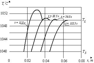
Figure 7 shows the temperature distribution in the twophase layer at selected solidification times $t$ for the $Z n 10$ alloy. Inside the layer, the alloy temperature changes monotonically from the solidus temperature $T_{S}=1040^{\circ} \mathrm{C}$ to the liquidus temperature $T_{L}=1050^{\circ} \mathrm{C}$. As can be seen form the graph, for the initial solidification times, for which the heat of crystallization flux is high, the temperature reaches its maximum at a certain point inside the layer and this maximal value is slightly higher than the liquidus temperature. The reason for this is the fact that the volumetric heat flux $\dot{q}_{V}$ generated in the solidification process in the two-phase zone of the alloy exceeds the heat flux removed from the layer.
Figure 7. Temperature distribution in a two-phase layer depending on the time for Zn10 with $B i_{C O N}=\infty, B=0$ and $S t e=0.081$
The solidification of pure metals during a continuous casting was investigated analytically, for instance, in works [4] (casting of bars) and [5] (casting of flat castings). In Ref. [5], the influence of the casting shape on the solidification process was additionally examined. In both studies, the stationary solidification front with respect to the crystallizer was determined by applying the superposition of two movements: the flow of liquid metal in the vertical direction (perpendicular to the surface of the crystallizer) and the movement of the solidification front in the direction perpendicular to the surface of the crystallizer wall. A special attention was paid to the thermal resistance of the contact layer between the solidified metal and the surface of the crystallizer. The dependence of the solidification front shape on the thermodynamic and flow parameters of the metal was also shown.
The proposed model of the cold wall solidification of the alloy used in this paper is shown in Figure 1. Now it is time to present the analytical method of determining the solidification front shape in the continuous casting of a brass plate (Figure 8). To determine the stationary solidification fronts with respect to the crystallizer, the superposition of two movements: vertical flow of the liquid alloy through the crystallizer and the horizontal movement of the solidification front inside the crystallizer, was used. It was assumed that the appropriate selection of the alloy flow rate and the solidification rate (superposition of both movements) ultimately leads to the formation of a solidification front that is immobile in relation to the crystallizer. Obviously, the shape of this solidification front depends on the thermodynamic and flow parameters of the alloy.
Due to the analysis of the alloy – not a pure metal –solidification phenomenon in the continuous casting process, a stratified solidification front related to the phase space between boundaries the liquidus and solidus of a given alloy is adopted as opposite to a sharp solidification front that is characteristic for pure metals. The other assumptions are as follows:
- the liquid alloy with the temperature $T_{C}$ flows into the crystallizer (Figure 8$)$ where it contacts the cold flat wall with the surface temperature $T_{W}$,
- the surface temperature of the wall is lower than the freezing point of the alloy and satisfies inequality $T_{W}<T_{S}$.
In addition, on the surface of the solidus layer with the thickness $\delta_{S}$ there is the solidus temperature $T_{S}$ and at the distance $\delta_{L}$ there is the liquidus surface with the temperature $T_{L}$, which is slightly higher than the solidus temperature. The solidification time of the element of the liquid alloy stream, described by the Eq. (16), depends on the velocity of the alloy in the crystallizer in the direction of the $y$ -axis starting from the inlet to the crystallizer and is described by the Eq. [10]:
$t=\frac{y}{u}$, (21)
where u is the velocity of the alloy in the crystallizer and y is the travel path from the inlet to the crystallizer.
Comparing the equations determining the time of the solidification front movement (16) and the alloy movement time in the crystallizer (21), the stationary equation of the solidification front was obtained:
$\tilde{y}=\frac{P e}{4 S t e}\left[(2-S t e) \tilde{\delta}^{2}+\frac{4 \tilde{\delta}}{B i_{C O N}}\right]$, (22)
where the dimensionless coordinate of the solidification front position and the Peclet number are given by respectively.
$\tilde{y}=\frac{y}{H}$ and $P e=\frac{u H}{a_{S}}$,
Figure 8. The shape of the solidification front of Zn10 in a flat crystallizer for Ste $=0.081, B i_{C O N}=\infty$ and $B=0$
The stationary shape of the brass solidification front in relation to the crystallizer in the continuous casting of a flat cast is presented in Figure 8 for two Peclet numbers: Pe=1 and Pe=2. With an increase in the Peclet number (indirectly with an increase in the alloy flow velocity in the crystallizer), the solidification front in the direction of flow lengthens. This information is very important when designing the height of the crystallizer.
The two-phase layer on the solidifying surface of the alloy generates the phase change heat which is carried away through the solidified layer to the crystallizer surface. The amount of the generated heat decreases as the solidification process progresses. The heat of solidification causes a local temperature increase in the layer. The biggest increase in temperature is observed at the beginning of the solidification process. The analytical model used in this work, describing the solidification of brass, is simple and yet allows to determine very important macroscopic technological parameters of the alloy solidification: the solidification time and the shape of the alloy solidification front in the crystallizer.
The conducted theoretical research will allow metallurgists and founders to correctly analyze and design the solidification processes of alloys. They will allow a better understanding of the solidification phenomenon, which has a significant impact on the structure and strength properties of the obtained alloys as a result of solidification processes.
Future studies should be carried out using theoretical models that are even closer to real solidification conditions. For this purpose, non-stationary and fully non-linear equations describing the solidification process should be used. However, finding analytical solutions of these equations is extremely difficult. Of course, one can get their numerical solutions, but still the question of the correct interpretation of the results obtained in this way remains an important challenge.
This work is supported by the program of the Polish Minister of Science and Higher Education under the name "Regional Initiative of Excellence” in 2019 - 2022, Project No. 003/RID/2018/19, funding amount 11 936 596.10 PLN.
|
$\tilde{a}$ |
dimensionless ratio of thermal diffusivities, |
|
$a_{L}$ |
thermal diffusivity of the liquid alloy, m2. s-1 |
|
$a_{S}$ |
thermal diffusivity of the solidified layer, m2. s-1 |
|
$B$ |
dimensionless overheating parameter |
|
$B i_{C O N}$ |
dimensionless Biot number in the contact layer |
|
$C_{L}$ |
specific heat of the liquid, J. kg-1. K-1 |
|
$C_{S}$ |
specific heat of the solidified layer, J. kg-1. K-1 |
|
$F O$ |
dimensionless Fourier number |
|
$h$ |
heat transfer coefficient at the solidification front, W. m-2. K-1 |
|
$h_{C O N}$ |
heat transfer coefficient at the contact layer, W. m-2. K-1 |
|
$H$ |
width of the channel, m |
|
$\tilde{k}$ |
dimensionless ratio of heat conductivities |
|
$k_{L}$ |
heat conductivity of the liquid metal, W. m-1. K-1 |
|
$k_{m}$ |
average heat conductivity of the mixture of liquidus and solidus, W. m-1. K-1 |
|
$k_{S}$ |
heat conductivity of the solidified layer, W. m-1. K-1 |
|
$L$ |
latent heat of liquid, J. kg-1 |
|
$P e$ |
dimensionless Peclet number |
|
$\dot{q}$ |
heat flux, W. m-1 |
|
$\dot{q}_{V}$ |
volume heat flux, W. m-3 |
|
$S$ |
dimensionless volume fraction of the solid phase |
|
Ste |
dimensionless Stefan number |
|
t |
time, s |
|
$T$ |
temperature, K |
|
$T_{C}$ |
temperature of the liquid metal, K |
|
$\bar{T}_{C}$ |
average liquid metal temperature, K |
|
$T_{C 0}$ |
initial liquid metal temperature, K |
|
$T_{L}$ |
liquidus temperature, K |
|
$T_{S}$ |
solidus temperature, K |
|
$T_{W}$ |
wall temperature, K |
|
$u$ |
velocity, m. s-1 |
|
$u_{L}$ |
velocity of the liquidus, m. s-1 |
|
$u_{S}$ |
velocity of the solidus, m. s-1 |
|
$\tilde{y}$ |
dimensionless coordinate of the solidification front position |
|
Greek symbols |
|
|
$\tilde{\delta}$ |
dimensionless position of the solid layer |
|
$\delta_{L}$ |
position of the liquidus, m |
|
$\delta_{S}$ |
position of the solidus, m |
|
$\delta_{S}^{\prime}$ |
position of the volume fraction S |
|
$\Delta$ |
thickness of the two-phase layer, m |
|
$\tilde{\Delta}$ |
dimensionless thickness of the two-phase layer |
|
$\bar{\theta}_{C}$ |
average dimensionless overheating temperature of the liquid |
|
$\rho_{L}$ |
liquid density, kg. m-3 |
|
$\rho_{S}$ |
density of the solidified layer, kg. m-3 |
|
$\tau$ |
dimensionless time |
[1] Beckermann, C., Viskanta, R. (1993). Mathematical modeling of transport phenomena during alloy solidification. Applied Mechanics Reviews, 46(1): 1-27. https://doi.org/10.1115/1.3120318
[2] Choudhary, S.K., Mazumdar, D. (1994). Mathematical modelling of transport phenomena in continuous casting of steel. ISIJ International, 34(7): 584-592. https://doi.org/10.2355/isijinternational.34.584
[3] Ni, J., Incropera, F.P. (1995). Extension of the continuum model for transport phenomena occurring during metal alloy solidification-I. The conservation equations. International Journal of Heat and Mass Transfer, 38(7): 1271-1284. https://doi.org/10.1016/0017-9310(94)00236-O
[4] Prescott, P.J., Incropera, F.P. (1996). Convection heat and mass transfer in alloy solidification. Advances in Heat Transfer, 28: 231-338. https://doi.org/10.1016/S0065-2717(08)70142-4
[5] Han, Z.Q., Liu, B.C. (2003). Mathematical modeling on transport phenomena in solidification of Fe-C alloy. International Journal of Cast Metals Research, 15(3): 211-215. https://doi.org/10.1080/13640461.2003.11819485
[6] Krane, M.J.M. (2010). Modeling of transport phenomena during solidification processes. In: Furrer, D.U., Semiatin S.L. (Eds.) ASM Handbook, Metals Process Simulation. ASM International. https://doi.org/10.31399/asm.hb.v22b.a0005525
[7] Rizzo, E.D.S., Santos, R., Beckermann, C. (2003). Modeling solidification and mushy zone deformation of alloys. Journal of the Brazilian Society of Mechanical Sciences and Engineering, 25(2): 180-184. https://doi.org/10.1590/S1678-58782003000200011
[8] Lipnicki, Z., Pantoł, K., Weigand, B. (2014). Role of the contact layer in continuous casting of thin metal rods. Archives of Metallurgy and Materials, 59(1): 168-172. https://doi.org/10.2478/amm-2014-0027
[9] Poole, G.M. (2014). Mathematical modeling of solidification phenomena in electromagnetically stirred melts. Ph.D. dissertation. Department of Metallurgical and Materials Engineering, University of Alabama, USA.
[10] Lipnicki, Z., Pantoł, K. (2015). Role of the continuous casting forms on the shape of the solidified crust. Archives of Metallurgy and Materials, 60(4): 2553-2557. https://doi.org/10.1515/amm-2015-0413
[11] Cabralesa, R.C., Moragab, N.O. (2017). Mathematical modeling of macrosegregation during solidification of binary alloy by Control Volume Finite Element Method. Applied Mathematical Modelling, 52: 288-305. https://doi.org/10.1016/j.apm.2017.07.051
[12] Niaz, U., Isac, M.M., Guthrie, R.I.L. (2020). Numerical modeling of transport phenomena in the horizontal single belt casting (HSBC) process for the production of AA6111 aluminum alloy strip. Processes, 8(5): 529-543. https://doi.org/10.3390/pr8050529
[13] Mochnacki, B., Suchy, J.S. (1993). Modelowanie i symulacja krzepnięcia odlewów (in Polish). Wydawnictwo Naukowe PWN, Warsaw.