Mallikharjuna Rao Tarla* | Srinivasa Rao Surapaneni | Konnanilkunnathil Thomas Varughese
© 2021 IIETA. This article is published by IIETA and is licensed under the CC BY 4.0 license (http://creativecommons.org/licenses/by/4.0/).
OPEN ACCESS
Exergy analysis gaining importance as an engineering analysis tool for energy systems. This paper explores the possibility of decreasing exergy reduction in thermal power plant components like boiler, turbine and condenser and thus increasing exergetic efficiency of Power plants by redesigning the existing design of some important components like platen super heater, final super heater, re heater, condenser, so that resource sustainability improves. The method suggested for exergy destruction in condenser is by using Heat pipes and application of heat pipes for steam condensation has been validated with experimental results.
exergy, heat pipes, sustainability, platen super heater, final super heater, reheater, condenser, exergetic efficiency
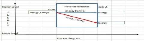
The Exergy is the work potential of a given amount of energy under existing environment. It is well known that energy is constant and during every process, the energy changes form, but it is not the case with exergy. Exergy destruction takes place during every irreversible process and is conserved only during reversible process. Almost all known engineering processes are irreversible process. Due to this, there will be exergy reduction during every engineering process. The concept is presented in Figure 1.
Figure 1. Concept of energy and exergy transfer
The variation of exergy during the process is called ‘‘exergy consumption’’ or “exergy destruction”. Hence, it is sure that for every useful process like electricity production, transportation, or manufacturing, there will be a definite amount of exergy destruction.
Similarly, the natural process like cloud formation, photosynthesis is also causing lot exergy destruction.
At present major Power generation for human use is from the fossil fuels like coal, oil and gas. According to US Department of Energy, around 15 TW of energy being explored annually from fossil fuels. These fuels are being used with low exergetic efficiency equipment causing huge amount of entropy production. The global entropy production alone from the thermal power plants is 17 GW.
The energy and exergy analysis of a steam power plant was carried out by so many investigators [1-6]. But all these investigators analyzed Exergy and energy analysis only but the suggestions for improvement of exergy efficiency was not addressed which is essential for smooth progress of living organisms on this earth.
It is true that during every engineering process there will be some exergy reduction. So, where does this destructed exergy dissipate? According to Gouy-Stodola theorem [7], as exergy is consumed, equivalent amount of entropy is necessarily being generated. Part of resource converted into desired work and rest is exergy destruction which enter back into nature, but unfortunately in the form thermal pollution.
Rosen [8] brought out the relations between exergy and environment and also described how the exergy influences the environment changes. Exergy had also been proposed as a holistic ecosystem indicator [9] and entropy as a controlling factor for ecological process [10]. It is also reported that applications of exergy on environmental impact is being increased continuously as per different investigators indicated in their publications [11-18].
It is opinioned that, huge exergy destruction in the natural process is one of reason for earth quakes, cyclone etc. According to the literatures [19-21] the maximum entropy production has a great influence on global climate conditions. This maximum entropy production is due to continuous exergy destruction.
The literature survey indicates that the exergy destruction will have negative impact on the environment. Thus, to be conscious for the environment, it is an essential requirement for optimal use of resources which could serve as immediate solutions.
Then a relation between sustainability index and exergy destruction was established by Regulagadda et al. [1] in his works.
The Sustainability Index, SI=1/DP, where DP=Exergy destruction/Exergy input.
Therefore, SI=Exergy Input/Exergy destruction.
This relation implies that, Sustainability index increases with decrease in exergy destruction. This indicates if exergy efficiency increases the sustainability of energy sources improves. Hence it is essential, that reduction in exergy destruction is inevitable for sustainability of existing energy sources.
But the available literature much discussed the effect of exergy destruction on environment, but seldom discussed about solutions/methods to decrease exergy destruction.
In this paper, three different design configurations have been proposed to reduce exergy destruction in boiler, turbine and condenser, which are vital components of a power plant, to address the prevailing gap in the available literature.
The reasons for the exergetic efficiency loss have been investigated and proposals for modifications of combustion parameters, boiler insualtion propertites, redesign of the boiler sub components, turbine insulation modifcations and condenser tubes mdofications are proposed so that there will be enhancement in exergetic efficiency. The proposed modifcations are listed in Table 1.
Table 1. Different proposals to reduce exergy destruction
|
Component |
Reasons for Large Exergy Destruction |
Technique to reduce Exergy Reduction |
|
Condenser |
1. Presence of air pockets 2. Exhaust condensate losses 3. Direct Heat Transfer between steam and cooling water. |
The decrease in the exergy destruction in the condenser can be achieved by successive cooling of steam. This type cooling is possible by applying specifically designed heat pipes in place of conventional non-ferrous tubes. As a result, exergy destruction due to heat transfer will be reduced and exergetic efficiency will improve by 30%. |
|
Boiler |
1. Irreversible nature of combustion 2. Flue gas losses 3. Heat energy Transfer between the high temperature combustion gases and the relatively low temperature steam streaming in platen superheater, final super heater, reheater etc. |
1. Improving combustion parameters and redesigning the heat exchangers for better heat transfer. 2. Improving the boiler skin insulation properties 3. Redesigning the Platen super heater, final super heater and reheater with heat pipes to reduce temperature difference between steaming fluids. By implementing by above cumulatively 4% total exergy reduction in the boiler. |
|
Turbine |
1. Irreversible nature steam expansion in blades 2. Exhaust steam losses 3. Heat Transfer between the high temperature turbine barrel and atmosphere this because of relatively poor insulation on turbines barrels. |
Improvement in insulation properties (used on turbine barrel) will result the exergy destruction to an extent of 0.5 %. |
The modern steam power plant works according to the Modified Rankine cycle. But in practice, this ideal cycle is impossible, because of fluid and gas friction. Though the assumption of adiabatic flow in turbine is valid, but because of friction in the expansion and compression in turbines, pumps etc. the expansions are not reversible. Due to this reason, there will be exergy destruction in these processes. In order to increase exergetic efficiency of the cycle, the exergy analysis of power plant components is to be improved. The proposals for improvement in exergetic efficiency can be suggested/ discussed by choosing an existing power plant as a model/Case Study.
4.1 Exergy calculations for case study
The exergy equations described in Appendix A were used to calculate exergy transactions across boiler, turbine and condenser of a 210 MW power plant as a case study. The different operating parameters considered for these calculations are given in Table 2 (Boiler parameters), Table 3 (Turbine parameters) and Table 4 (condenser parameters). The rated Capacity of the Plant is 210 MW, located in Maharashtra state, India. Load at the time of consideration: 191 MW.
Based on this data, Exergy destruction and exergetic efficiency were calculated as per formulae presented in the Appendix and presented in the Table 5. In exergy calculations, selection of reference or dead state is of extreme importance. In the present case of exergy analysis, the dead state pressure (p0) and temperature (T0) are considered as 1 bar and 298 K i.e. 25℃ respectively. The dead state enthalpy h0 and S0 are, h0=104.9 kJ/kg, S0=0.367 kJ/kg-K.
The above results are compared with those available in the available literature and are presented in Table 6.
Table 2. Boiler parameters
|
Sl. No |
Parameter |
Numerical value |
|
1 |
Coal calorific value |
3,500 kCal/kg or 14,654.5 kJ/kg |
|
2 |
Quantity of coal used |
144 t/hr or 40 kg/s |
|
3 |
Mass of primary air |
179.9 t/hr at 325℃ |
|
4 |
Mass of secondary air |
611.4 t/hr at 318℃ |
|
5 |
Power required for 2, FD fans |
2 x 750 kW |
|
6 |
Boiler Feed water |
594 t/hr or 165 kg/s |
|
7 |
Feed water temperature (Economizer outlet) |
286℃ |
|
8 |
Final Super heater out let flow |
594 t/hr or 165 kg/s |
|
9 |
Re heater outlet flow |
554.2 t/hr or 154 kg/s |
Table 3. Existing steam flow parameters of the turbine
|
Sub component |
Mass in kg/s |
Temperature ℃ |
Pressure in bar |
Specific Enthalpy in kJ/kg |
Specific Entropy in kJ/kgK |
|
HP Turbine inlet |
165 |
535 |
128 |
3320 |
6.55 |
|
HP Turbine outlet |
154 |
330 |
26 |
3076.8 |
6.74 |
|
HP extraction |
11 |
378 |
40 |
3160.3 |
6.69 |
|
IP Turbine Inlet |
154 |
535 |
23 |
3542.5 |
7.459 |
|
IP Turbine outlet |
107 |
184 |
1.5 |
2840 |
7.57 |
|
IP Extraction |
47 |
265 |
2.8 |
3000 |
7.61 |
|
LP Turbine inlet |
107 |
184 |
1.5 |
2840 |
7.57 |
|
LP Turbine outlet |
107 |
46 |
0.09 |
2400 |
7.62 |
Table 4. Existing details of the condenser
|
Parameter |
Numerical value |
|
Unit Load |
191 MW |
|
Condenser Steam inlet temperature |
46 ℃ |
|
Condenser steam inlet pressure |
0.09 bar |
|
Condenser cooling water inlet Temp |
26.62 ℃ |
|
Condenser cooling water outlet Temp |
36.65 ℃ |
|
Total Tubes in condenser |
19,208 |
|
Outside diameter of condenser tube |
25.40 mm |
|
Inside diameter of condenser tube |
24.00 mm |
|
Condenser Tube Length |
11.28 m |
|
Load on Condenser |
221171743.8 Kcal/hr, 260 MW |
|
Cooling water Flow |
21033.95 t/hr, 5842.76 kg/s |
Table 5. Exergy efficiency of the above-described plant
|
Component |
Exergy destruction |
Exgertic Efficiency |
|
Boiler |
400.00 MW |
52.9 % |
|
Turbine |
16.15 MW |
97.0 % |
|
Condenser |
10.2 MW |
30.0 % |
Table 6. Comparisons of exergetic efficiencies with literature
|
Capacity (MW)/Reference. No |
Exergetic Efficiency in percentage |
||
|
Boiler |
Turbine |
Condenser |
|
|
600/[22] |
36.75 |
85.45 |
NA |
|
320/[22] |
48.23 |
90.03 |
NA |
|
300/[22] |
45.47 |
88.60 |
NA |
|
457/[23] |
36.45 |
84.19 |
NA |
|
210/[24] |
40.00 |
77.00 |
21.45 |
|
396/[25] |
43.80 |
73.50 |
26.40 |
|
500/[26] |
49.51 |
NA |
NA |
|
315/[27] |
40.00 |
NA |
28.00 |
|
Case Study under consideration |
52.6 |
83.0 |
22 |
Note: NA – Not available
The reasons for the exergetic efficiency loss have been investigated and proposals for modifications of combustion parameters, boiler insulation properties, redesign of the boiler sub components, turbine insulation modifications and condenser tubes modifications are proposed so that there will be enhancement in exergetic efficiency. The proposed modifications are as follows:
5.1 Proposals to increase exergetic efficiency in condenser
5.1.1 Probable reasons for exergy destruction
5.1.2 Proposal to reduce exergy destruction in condenser
A complete exergetic analysis of an existing Condenser could help to identify sources of exergy loss and possible improvements. Analyzing exergy in a condenser, either for design or for analysis, is not straightforward. The three main causes of irreversibility are heat transfer between the flows, pressure losses due to fluid friction, and dissipation of energy to the environment; these three phenomena can also occur simultaneously. There exist other problems of minor effects such as, stream wise conduction in the walls of the heat exchanger.
It is herewith proposed that the exergy destruction reduction is possible in the condenser by successive cooling the dumped steam. That is, the dumped steam is not directly cooled by cooling water. The heat energy from the steam is transferred to a third liquid at a temperature higher than that of the cooling water and then the heat energy from this third liquid is transferred to the cooling water. The scheme is depicted in Figure 2.
Figure 2. Scheme of proposed heat transfer
It is known, that the exergy destruction depends on the temperatures of the steam and environment temperature. According to Figure 3, the steam is exchanging temperature with cooling water viz an intermediate liquid. Hence, there will be comparatively less exergy destruction in this reconfigured method.
5.1.3 The exergy calculation of heat pipe based proposed condenser will be as follows
Figure 3. Line diagram of heat pipe condenser
The line diagram of proposed heat pipe based condenser will be as in Figure 3. Steam and cooling water enter into the condenser as shown in figure and condensate drops from the bottom. Based on the inference given in Ref. [28] the exergy calculations are as below:
For Part B
where steam condenses into water and fluid inside the heat pipe evaporates.
∆Ǝ=UoAo(πT-1)2/πT] [29]
Uo=Overall heat transfer coefficient=2406 W/m2.K
Ao=Overall heat transfer area=1.3 m2
πT=the ratio of input thermodynamic temperature of the streams=46/39.02=1.179
Applying numerical,
Hence, ∆Ǝ=2406x1.3x (1.179-1)2/1.179=85 W
where steam condenses into water and fluid inside the heat pipe evaporates.
∆Ǝ=UoAo(πT-1)2/πT] [29]
Uo=Overall heat transfer coefficient=2406 W/m2.K
Ao=Overall heat transfer area=1.3m2
πT=the ratio of input thermodynamic temperature of the streams=46/39.02=1.179
Applying numerical,
Hence, ∆Ǝ=2406x1.3x(1.179-1)2/1.179=85 W
For Part A
where cooling water gets heated and vapor inside heat pipe condenses into liquid.
∆Ǝ=Tenv[C1ln(T1’’/T1’)+C1(T1’-T1’’)/T2’]
Cc=Heat capacity of water stream, W/k
T1’=cooling water at inlet=299.62 K 302.62
T1’’=cooling water at outlet=310.26 K 312.65
T2’=vapor temp. Inside heat pipe before condensation=312.02 K
Hence,
∆Ǝ=301x5843x4.178x [ln (310.26/299.62) +(299.62-310.26)/312.02]=7348028.3x(0.0349-0.0341)=5878.4 kW
Total Exergy in Part A and Part B=5878.4 kW+85 kW=5963.4 ≈5963 kW
Reduction of exergy reduction by using Heat pipe condenser= (11,761-5963) kW=5,798 kW≈5.9 MW
Hence Exeretic efficiency= (14.57-5.82)/14.57=60%
Hence it can be concluded that, with the use of Heat pipes in place of conventional nonferrous pipes, there will be an increase of 30% of exergetic efficiency in the condenser.
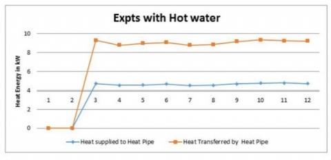
5.2 Development of heat pipe for steam condensation
Figure 4. Single heat pipe performance with Hot water
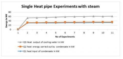
Figure 5. Single heat pipe performance with steam
(a)
(b)
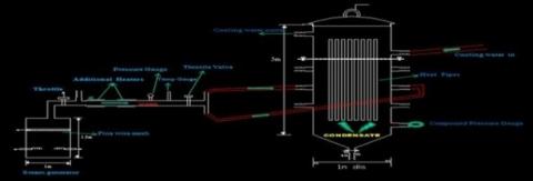
(c)
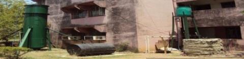
Figure 6. (a) Line diagram of experimental set up; (b) Actual photograph of experimental set up; (c) Condensate outflow from heat pipe condenser
For the purpose of this steam condensation, a heat pipe was developed and fabricated (First time in the history of heat pipe) and detailed in Ref. [30]. The developed heat pipe validated for its performance with hot water and steam and results are presented in Figures 4 and 5.
A steam condenser was developed with specially designed heat pipes and laboratory experiments were conducted. The experimental set up presented in the Figure 6a.
In this experiment, number of heat pipes considered are 16. A miniature steam generator of heating capacity 33 kW is employed to supply the steam. A superheating system is arranged to superheat the generated steam. The superheated steam was fed into the heat pipe condenser. The parameters of the steam are measured before entering into condenser. The condensate is collected at the bottom tank. The cooling water is supplied from the overhead tank. The inlet and out let temperature of cooling water is measured using thermometers. The actual photo of experimental set up is given in Figure 6b and condensate flow is shown in Figure 6c. This picture clearly indicates that the heat pipe-based condenser consistently transfers the dumped steam energy to the cooling fluid.
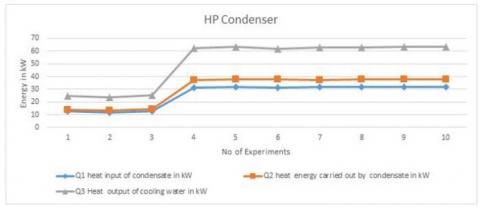
The performance of this heat pipe based condenser calculated and presented in Figure 7.
Figure 7. Performance of heat pipe based condenser
Probable Reasons for Large Exergy Destruction
1. Irreversible nature of combustion and high temperature of combustion.
2. Heat Losses from the skin of boiler.
3. Exhaust Flue gas losses.
4. Heat Transfer between the high temperature gases and the relatively low temperature steam.
The present paper proposes the reduction exergy reduction in the boiler by following methods.
(a) The skin of boiler is covered by insulation which is designed (According to ASTM c 680 standards) to 60℃. It is proposed to improve the insulation capacity to 40℃ so that exergy destruction due to heat loss will be reduced by 44%.
(b) The combustion in the boiler may be defined as release of heat exergy from exothermic chemical reaction by burning fuel [31]. Dunbar and Lior [32] clearly brought the combustion irreversibilites. According to them the inefficiencies in the combustion system are by chemical reactions, heat transfer and to lesser extent by friction and mixing. According to Tsatsaronis et al [33], measures for improving the thermodynamic performance of combustion process should concentrate on the avoidable endogenous exergy destruction and the avoidable exogenous exergy destruction. The first option is possible by changes in the combustion process where as second option is possible by changing the performance of the remaining plant components in the structure of the overall boiler.
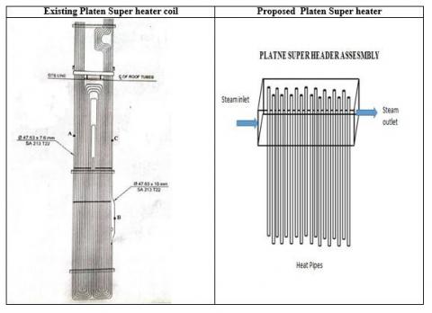
Figure 8. Platen super heater modification
Figure 9. Final super heater modification
Figure 10. Re heater modification
Figure 11. Layout of turbine
In this paper authors are opted second method that is changing performance of plant components to reduce combustion exergy destruction. The proposal by authors is replacing the existing platen super heater, final super heater and reheater system with heat pipe based platen super heater, final super heater and reheaters. The proposed assembly is shown in Figures 8-10.
The heat pipes proposed for this proposal is sodium based high temperature resistant. Because of two phase heat transfer mechanism of heat pipes the heat transfer coefficient improves significantly and hence no of tubes required for heat duty will decrease. Around 350 heat pipes will meet heat load of the platen super heat header.
With his arrangement the heat transfer efficiency will increase and also the combustion exergy destruction will decrease by 3% because reduction temperature difference among working streams. The increase in boiler exergetic efficiency due to above modification will increase to 56.1%.
The line diagram of a 210 MW turbine is shown in Figure 11.
There are three separate barrels for in which HP rotor, IP rotor and LP rotor are encapsulated with insulation.
Exergy Calculation Existing Turbine
C1. Probable Reasons for Exergy Destruction
*Irreversible nature steam expansion in blades
* Exhaust steam losses
*Heat Transfer between the high temperature turbine barrels and atmosphere, this is because of relatively poor insulation on turbines insulations
Proposal For improvement in Exergetic Efficiency
The present insulation on turbine barrels is designed to 60℃ only. It is proposed to improve the insulation capacity to 40℃, so that exergy destruction due to heat loss will be reduced and exergetic efficiency will improve to 0.16%.
With all the above modification in the boiler, turbine and condenser the plant efficiency can be worked as per following Table 7.
The energy efficiency of the power plant (accordingly to first law of thermodynamics) also increases by these modifications.
Table 7. Exergetic efficiency improvement
|
|
Boiler |
Turbine |
Condenser |
|
Proposed design |
56.10 |
97.16 |
60.00 |
|
Power Plant considered as Case Study |
52.9 |
97.00 |
30.00 |
|
Maximum efficiency reported in the literature |
49.51 [25] |
90.03 [26] |
26.40 [25] |
The following conclusions are drawn from the study.
(a) Exergy destruction causes thermal pollution that can harmfully impact the environment and to improve the sustainability of energy sources, reduction exergy is essential.
(b) For boilers, the exergy destruction can be reduced further by 3.2% to the existing design by reconfiguring arrangement of internal components like super heaters, re heaters and other concerned parts, improving combustion parameters and boiler insulation properties.
(c) For turbines, a 0.16% reduction in exergy destruction is possible by improving the quality of thermal insulation applied on turbine barrels.
(d) For condensers, a 30% reduction in the exergy destruction can be obtained by successive cooling of steam condensation. This was made possible by employing the heat pipes in the condenser.
(e) Experiments with heat pipe based condenser confirms that heat pipes are efficient for steam condensation and can be used in steam condensers.
(f) Finally, it may be concluded that if exergy destruction decreases with the boiler, turbine and condenser, there will be a decrease in exergy destruction in overall power plants. Thus, exergetic efficiency of the cycle is expected to be improve approximately 35%.
(g) Further improvement in Boiler is possible by augmenting feed water heaters, boiler feed pump etc., which left as future research scope.
The authors thank to M/s. Central Power Research Institute for sponsoring the experimental expenditure and also according permission to publish this paper.
Formulae of Exergy Calculations
The exergy of a system, Ǝ, at a specified state is given by the expression [34]:
Ǝ=(U-U0)+p0(V-V0)–T0(S-S0)+KE+PE
Exergy balance for a closed system can be evaluated by,
$\Delta \exists=$ change in exergy $=\int_{1}^{2}\left(1-\frac{T_{0}}{T_{b}}\right) \delta Q-\left[W-p_{0}\left(V_{2}-\right.\right.$$\left.\left.V_{1}\right)\right]-T_{0} \sigma$ [34]
Using the above equations, the exergy calculations for boiler, turbine and condenser are calculated and presented in the paper.
[1] Regulagadda, P., Dincer, I., Naterer, G.F. (2010). Exergy analysis of a thermal power plant with measured boiler and turbine losses. Applied Thermal Engineering, 30(8-9): 970-976. https://doi.org/10.1016/j.applthermaleng.2010.01.008
[2] Rosen, M.A. (2001). Energy- and exergy-based comparison of coal-fired and nuclear steam power plants. Exergy, An International Journal, 1(3): 180-192. https://doi.org/10.1016/S1164-0235(01)00024-3
[3] Habib, M.A., Zubair, S.M. (1992). Second-law-based thermodynamic analysis of regenerative-reheat Rankine-cycle power plants. Energy, 17(3): 295-301. https://doi.org/10.1016/0360-5442(92)90057-7
[4] Dincer, I., Al-Muslim, H. (2001). Thermodynamic analysis of reheat cycle steam power plants. International Journal of Energy Research, 25(8): 727-739. https://doi.org/10.1002/er.717
[5] Sengupta, S., Datta, A., Duttagupta, S. (2007). Exergy analysis of a coal‐based 210 MW thermal power plant. International Journal of Energy Research, 31(1): 14-28. https://doi.org/10.1002/er.1224
[6] Kaushik, S.C., Reddy, V.S., Tyagi, S.K. (2011). Energy and exergy analyses of thermal power plants: A review. Renewable and Sustainable Energy Reviews, 15(4): 1857-1872. https://doi.org/10.1016/j.rser.2010.12.007
[7] Nag, P.K. (2006). Text Book “Basics and Applied Thermodynamics”. Tata Mc- Graw Hill Publisher.
[8] Rosen, M.A. (2009). Enhancing ecological and environmental understanding with exergy: Concepts and methods. In Proceedings of the 4th IASME/WSEAS International Conference on Water Resources, Hydraulics & Hydrology (WHH’09), pp. 94-103.
[9] Marques, J.C., Pardal, M.Ã., Nielsen, S.N., Jørgensen, S.E. (1998). Thermodynamic orientors: Exergy as a holistic ecosystem indicator: A case study. In Eco Targets, Goal Functions, and Orientors, pp. 87-101. https://doi.org/10.1007/978-3-642-58769-6_6
[10] Mauersberger, P. (1995). Entropy control of complex ecological processes. Englewood Cliffs, NJ: Prentice-Hall.
[11] Creyts, J.C., Carey, V.P. (1997). Use of extended exergy analysis as a tool for assessment of the environmental impact of industrial processes. In M. L. Ramalingam, J. L. Lage, V.C. Mei, and J.N. Chapman (Eds.), Proceedings of the ASME Advanced Energy Systems Division, AES-Vol. 37, pp. 129-137.
[12] Gunnewiek, L.H., Rosen, M.A. (1998). Relation between the exergy of waste emissions and measures of environmental impact. International Journal of Environment and Pollution, 10(2): 261-272. https://doi.org/10.1504/IJEP.1998.005149
[13] Rosen, M.A., Dincer, I. (1997). On exergy and environmental impact. International Journal of Energy Research, 21(7): 643-654. https://doi.org/10.1002/(SICI)1099-114X(19970610)21:7%3C643::AID-ER284%3E3.0.CO;2-I
[14] Sciubba, E. (1999). Exergy as a direct measure of environmental impact. ASME Adv Energy Syst Div Publ Aes, 39: 573-581.
[15] Wall, G., Gong, M. (2001). On exergy and sustainable development-Part 1: Conditions and concepts. Exergy, An International Journal, 1(3): 128-145. https://doi.org/10.1016/S1164-0235(01)00020-6
[16] Jorgensen, S.E., Svirezhev, Y.M. (2004). Towards a Thermodynamic Theory for Ecological Systems. New York: Elsevier.
[17] Connelly, L., Koshland, C.P. (1997). Two aspects of consumption: Using and exergy-based measure of degradation to advance the theory and implementation of industrial ecology. Resources, Conservation and Recycling, 19: 199-217. https://doi.org/10.1016/S0921-3449(96)01180-9
[18] Connelly, L., Koshland, C.P. (2001). Exergy and industrial ecology-Part 1: An exergy-based definition of consumption and a thermodynamic interpretation of ecosystem evolution. Exergy, an International Journal, 1(3): 146-165. https://doi.org/10.1016/S1164-0235(01)00021-8
[19] Ozawa, H., Ohmura, A., Lorenz, R.D., Pujol, T. (2003). The second law of thermodynamics and the global climate system: A review of the maximum entropy production principle. Reviews of Geophysics, 41(4). https://doi.org/10.1029/2002RG000113
[20] Carsten Herrmann-Pillath. (2011). Revisiting the Gaia Hypothesis: Maximum Entropy, Kauffman’s ‘Fourth Law’ and Physiosemeiosis, Frankfurt School-working Paper Series.
[21] Feng, L.H., Luo, G.Y. (2009). Maximum entropy method and Seismic frequency - magnitude relation. Soft Computing, 13(10): 979-983.
[22] Kaushik, S.C., Reddy, V.S., Tyagi, S.K. (2011). Energy and exergy analyses of thermal power plants: A review. Renewable and Sustainable Energy Reviews, 15(4): 1857-1872. https://doi.org/10.1016/j.rser.2010.12.007
[23] Erdem, H.H., Akkaya, A.V., Cetin, B., Dagdas, A., Sevilgen, S.H., Sahin, B., Atas, S. (2009). Comparative energetic and exergetic performance analyses for coal-fired thermal power plants in Turkey. International Journal of Thermal Sciences, 48(11): 2179-2186. https://doi.org/10.1016/j.ijthermalsci.2009.03.007
[24] Varun, N.N., Satyanarayana, G. (2014). Exergy analysis of 210 MW of VTPS. International Journal of Latest Trends in Engineering and Technology, 4(2): 84-93.
[25] Aljundi, I.H. (2009). Energy and exergy analysis of a steam power plant in Jordan. Applied Thermal Engineering, 29(2-3): 324-328. https://doi.org/10.1016/j.applthermaleng.2008.02.029
[26] Rosen, M.A., Dincer, I. (2004). Effect of varying dead-state properties on energy and exergy analyses of thermal systems. International Journal of Thermal Sciences, 43(2): 121-133. https://doi.org/10.1016/j.ijthermalsci.2003.05.004
[27] Rashad, A., El Maihy, A. (2009). Energy and exergy analysis of a steam power plant in Egypt. In 13th international conference on AS AT-13.
[28] Kays & London: Compact Heat Exchagners, Mc Graw Hill Copmpany publishers.
[29] Galović, A., Živić, M., Kokanović, M. (2000). Analysis of exergy destruction of an evaporator or/and a condenser. Strojarstvo, 51(1): 73-78.
[30] Rao, T.M., Rao, S.S. (2020). Steam condensation by heat pipes. International Journal of Physics, Conference series, 1473: 012028. https://doi.org/10.1088/1742-6596/1473/1/012028
[31] Smith, J.M., van Ness, H.C., Abbott, M. (1996). Introduction to Chemical Engineering Thermodynamics. 5th ed. McGraw-Hill, New York.
[32] Dunbar, W.R., Lior, N. (1994). Sources of combustion irreversibility. Combustion Science and Technology, 103(1-6): 41-61. https://doi.org/10.1080/00102209408907687
[33] Tsatsaronis, G., Morosuk, T., Koch, D., Sorgenfrei, M. (2013). Understanding the thermodynamic inefficiencies in combustion processes. Energy, 62: 3-11. https://doi.org/10.1016/j.energy.2013.04.075
[34] Moran, M.J., Shapiro, H.N., Boettner, D.D., Bailey, M.B. (2010). Fundamentals of Engineering Thermodynamics. John Wiley & Sons.