Ying Guan* | Minghai Li | Hongjiang Cui
© 2020 IIETA. This article is published by IIETA and is licensed under the CC BY 4.0 license (http://creativecommons.org/licenses/by/4.0/).
OPEN ACCESS
In view of the heat transfer and ventilation characteristics of the Insulated Gate Bipolar Transistor (IGBT) in the Electric Multiple Unit (EMU), the authors aim to improve the traditional fin structure of the air-cooled heat exchanger (ACHE) and propose the use of corrugated fin structure. Using the computational fluid dynamics (CFD) technology, the ACHE with new fin structure was numerically simulated, and the temperature field, velocity field and pressure field at different fin corrugation angles and the synergy between the fields were analyzed. The results show that the improved fin structure can make the fluid flow in a corrugated flow channel, effectively increase the flow distance, and thus significantly enhance the turbulence performance of the fluid in the ACHE; the fin corrugation angle of 120 degrees is the key design point; compared with the traditional fin structure, the new fin structure improves the synergy between the various fields and increases the heat exchange efficiency. The research findings provide new ideas for the design of this type of ACHE.
air-cooled heat exchanger (ACHE), CFD, turbulent kinetic energy, field synergy
The IGBT, as the core component of the inverter, is closely related to the power, economy, and reliability of the electric traction system in the EMUs, so it is very important to ensure a good heat dissipation environment for the IGBT, and high heat dissipation capacity of the IGBT radiator [1-3]. At present, the commonly used cooling methods for electronic components in EMUs include air cooling, water cooling and phase change cooling. Among them, water cooling and phase change cooling are mostly used for heat dissipation with high heat flux density; air-cooled heat exchangers are often used for heat dissipation of electronic devices with low heat loss and low heat flux due to their simple structure, high reliability, and secondary heat transfer [4]. The fin is one main heat exchange unit of the air-cooled heat exchanger, playing a key role in the heat transfer of the entire heat exchanger.
Domestic and foreign scholars have carried out a lot of research work on the structure, heat transfer performance and field synergy analysis of heat exchangers. Focke et al. [5] conducted simulation calculations on the plate heat exchanger wholly and partially, focusing on the influence of corrugation parameters [6]. Wang et al. [7] carried out theoretical calculation, simulation calculation and experimental research on the thermal resistance of IGBT finned radiator, and found that the simulation calculation can meet the engineering accuracy requirements. Liu et al. [8] through a combination of experiment and numerical simulation, studied the heat transfer performance of the cooling duct of the traction transformer in the high-speed train. Liu et al. [9] improved the flow channel of the plate-fin heat exchanger, applied Fluent software to calculate the flow characteristics of the fluid, and concluded that the improvement of the flow channel can promote the heat transfer efficiency of the heat exchanger based on the simulation results. Sahin et al. [10] studied the flow structure of the fluid in a tube-fin heat exchanger, and analyzed the influence of the flow channel on the time and phase turbulence of the fluid. Li et al. [11] conducted an experimental study on the heat transfer and pressure drop characteristics of a tube-fin heat exchanger with a new type of fin.
With the extensive use of the enhancement technology in heat exchanger, heat transfer is intensified, but it also causes the increase of flow resistance. Therefore, the optimization design method and evaluation of heat exchanger are very important [12-14]. One main optimization method taking the minimum cost as the objective function sacrifices the performance of the heat exchanger [15]; the thermodynamic method that uses the minimum entropy generation as the goal also has the disadvantage of entropy generation paradox [16]; the Academician, Guo [12], re-examined the physical mechanism of convective heat transfer based on innovative concepts [17], and proposed a field synergy theory between the flow field and temperature field, which strengthens the heat transfer process, and lowers the resistance. Thus, it has been well applied in energy saving and engineering [18-20].
Among domestic researches, there have been few research results about the ACHEs for EMUs, especially based on the use of field synergy theory. In the actual application of radiators, there is also a certain degree of inaccuracy, thus leading to problems such as large power consumption in the cooling system and idle heat dissipation capacity. Currently in the air-cooled heat exchangers for cooling electronic devices on the EMUs, the flat-fin is mostly used. With the continuous improvement of vehicle speed and power, the use of corrugated fin instead of the flat fin type can effectively improve the heat transfer effect under the premise of not changing the overall structure of the ACHE. Based on the CFD and field synergy methods, this paper analyzes the influence of the fin structure on the heat transfer and resistance characteristics of the ACHE. It shall provide a useful technical reference for the design of this type of radiator.
2.1 Physical model
The IGBT air-cooled heat exchanger consists of a baseplate and fins (Figure 1). For the baseplate, several IGBT modules are installed on one side, while fins with a height of 116 mm are on the other side. At present, the flat fin is generally used in the IGBT air-cooled heat exchanger of the EMUs. To realize heat transfer, the IGBT heat source first transfers heat to the baseplate through thermal conduction, and then the fins for secondary heat dissipation are used to transfer heat by convection heat transfer to the cooling air. The flow channel formed between the fins is an important space for heat exchange. Traditionally, a straight fin structure has been designed to reduce air flow resistance. However, as higher requirements have been proposed for heat exchange by the electrical components of the EMU, the ACHE structure should be more compact, and have higher flow resistance. In order to enhance the turbulence and heat transfer performance, the traditional straight fin should be changed to a corrugated structure.
Figure 2 shows a schematic plan of the cooling air flowing in the flow channel of the ACHE with improved fin, in which①-④ indicate the positions of the 4 monitoring points in the flow channel; the air in the flow channel continuously changes the direction of movement, increasing the flow (heat transfer) distance and enhancing the turbulent performance of fluid flow. Figure 3 is a three-dimensional view of the ACHE with the improved aluminum-made fin, the copper-made heat-conducting baseplate, and heat-insulating baffle plate. Using the tools such as stretching and array in Creo, a three-dimensional model was generated, as shown in Figure 3. Then, it’s imported into Gambit software for grid processing, and finally analyzed and calculated in Fluent software.
From Figure 3, the overall structure size of the ACHE fin model: 690mm×400mm×116mm. The geometric parameters of the simplified calculation area of the ACHE are shown in Table 1, where, λ is corrugation Height, β is the corrugation width, θ is the corrugation angle, x is the fin spacing, and L is the fin length. Figure 2 shows the mathematical relationship between λ, β, and θ, namely,
$\tan \frac{\theta }{2}=\frac{\beta }{2\lambda }$ (1)
From Eq. (1), λ, β, and θ are correlated, and the change of the corrugation angle will also lead to changes in corrugation height and width. To explore the influence of corrugated fins on the ACHE, the corrugation height was determined first, and the corresponding corrugation width was calculated at different corrugation angles in the three-dimensional modeling of fins.
According to the overall size of the ACHE and the requirements for heat exchange amount, comprehensive consideration was taken to determine the corrugation height for 14mm, under the condition that the total number of fins is determined.
Figure 1. Structure diagram of traditional IGBT air-cooled heat exchanger
Figure 2. Plan view of improved fins
Figure 3. Three-dimensional view of improved fin
Table 1. Geometric structure parameters of IGBT air-cooled heat exchanger fins
|
Parameter |
Value |
|
Width of radiator model W/mm |
400 |
|
Fin height H/mm |
116 |
|
Corrugation height λ/mm |
14 |
|
Corrugation width β/mm |
$\beta=2 \lambda \cdot \tan \frac{\theta}{2}$ |
|
Corrugation angle θ/° |
60, 90, 120, 150, 180 |
|
Spacing of fins x/mm |
40 |
|
Fin length L/ mm |
690 |
2.2 ACHE calculation equations
The convection heat exchange was conducted between the fluid working medium air and the fins, involving the flow problem. The system satisfied the law of conservation of mass and momentum. There were additional equations for turbulent motion.
The mathematical model was based on the following assumptions:
(1) The Newtonian fluid is used as working medium;
(2) The fluid is in a stable flow state;
(3) The buoyancy caused by the density difference is ignored;
(4) The effect of viscous dissipation is ignored.
For single-phase incompressible fluids, the governing equations in the three-dimensional rectangular coordinate system are as follows:
$\frac{\partial \left( \rho u \right)}{\partial x}+\frac{\partial \left( \rho v \right)}{\partial y}+\frac{\partial \left( \rho w \right)}{\partial z}=0$ (2)
where, ρ is the density; u, v, and w are the components of the velocity vector in the x, y, and z directions, respectively.
$\frac{\partial uu}{\partial x}+\frac{\partial uv}{\partial y}+\frac{\partial uw}{\partial z}=\nu \left( \frac{{{\partial }^{2}}u}{\partial {{x}^{2}}}+\frac{{{\partial }^{2}}u}{\partial {{y}^{2}}}+\frac{{{\partial }^{2}}u}{\partial {{z}^{2}}} \right)-\frac{\partial p}{\partial x}$ (3)
$\frac{\partial vu}{\partial x}+\frac{\partial vv}{\partial y}+\frac{\partial vw}{\partial z}=\nu \left( \frac{{{\partial }^{2}}v}{\partial {{x}^{2}}}+\frac{{{\partial }^{2}}v}{\partial {{y}^{2}}}+\frac{{{\partial }^{2}}v}{\partial {{z}^{2}}} \right)-\frac{\partial p}{\partial y}$ (4)
$\frac{\partial wu}{\partial x}+\frac{\partial wv}{\partial y}+\frac{\partial ww}{\partial z}=\nu \left( \frac{{{\partial }^{2}}w}{\partial {{x}^{2}}}+\frac{{{\partial }^{2}}w}{\partial {{y}^{2}}}+\frac{{{\partial }^{2}}w}{\partial {{z}^{2}}} \right)-\frac{\partial p}{\partial z}$ (5)
where, ν is the kinematic viscosity; p is the pressure on the fluid element.
$\frac{\partial uT}{\partial x}+\frac{\partial vT}{\partial y}+\frac{\partial wT}{\partial z}=a\left( \frac{{{\partial }^{2}}T}{\partial {{x}^{2}}}+\frac{{{\partial }^{2}}T}{\partial {{y}^{2}}}+\frac{{{\partial }^{2}}T}{\partial {{z}^{2}}} \right)$ (6)
where, T is the temperature; a is the thermal diffusivity of the fluid.
When the fluid flows in the flow channel of the new fin structure, the turbulence and turbulence dissipation rate of the fluid increased due to the change of the flow channel structure. The turbulent kinetic energy of fluid [21] is calculated in Eq. (7):
$\begin{align} & \frac{\partial \left( \rho \kappa \right)}{\partial t}+\frac{\partial \left( \rho {{u}_{j}}\kappa \right)}{\partial {{x}_{j}}}= \\ & {{C}_{\kappa }}-\rho \varepsilon +{{S}_{\kappa }}+\frac{\partial }{\partial {{x}_{j}}}\left[ {{\alpha }_{\kappa }}\left( \mu +{{\mu }_{t}} \right)\frac{\partial \kappa }{\partial {{x}_{j}}} \right] \\\end{align}$ (7)
where, uj is the velocity component in the j direction; κ is turbulent kinetic energy; ε is the turbulent dissipation rate; ακ is fluid Prandtl number corresponding to turbulent kinetic energy; Cκ is turbulent kinetic energy term caused by velocity gradient; Sκ is the turbulent kinetic energy term of the fluid.
The turbulent dissipation rate of the fluid [22] is calculated as:
$\begin{align} & \frac{\partial \left( \rho \varepsilon \right)}{\partial t}+\frac{\partial \left( \rho {{u}_{j}}\varepsilon \right)}{\partial {{x}_{j}}}={{C}_{\xi 1}}\frac{\varepsilon }{\kappa }{{C}_{\kappa }}- \\ & {{C}_{\xi 2}}\rho \frac{{{\varepsilon }^{2}}}{\kappa }+{{S}_{\varepsilon }}+\frac{\partial }{\partial {{x}_{j}}}\left[ {{\alpha }_{\varepsilon }}\left( \mu +{{\mu }_{t}} \right)\frac{\partial \varepsilon }{\partial {{x}_{j}}} \right] \\\end{align}$ (8)
where, μt is turbulence viscosity, $\mu_{t}=\frac{\rho C \kappa^{2}}{\varepsilon}$ ; μ is fluid viscosity; αε is fluid Prandtl number of turbulent dissipation rate; Cξ1, Cξ2, C are empirical constants; Sε is the source term of fluid turbulence dissipation rate.
2.3 Grid independence verification
Grid is a geometric expression form of CFD model and an important carrier for simulation analysis. The quality of the grid affects the calculation accuracy and efficiency of CFD. For the specific issue, the quality of the grid is closely related to its geometric characteristics, flow characteristics and flow field solving algorithms. This model contains many thin fin plates with very small dimensions. The tetrahedral unstructured grids were generated. In order to ensure the accuracy of the numerical simulation calculation results, the independence verification was conducted on the fin model with corrugation angle θ=120° using the three different numbers of grid. Figure 4 shows the changes of the average cross-sectional temperature at each monitoring point under different grid numbers. With the number of grids 1.47×10⁶ and 1.62×10⁶, the average cross-sectional temperature of the ACHE at different monitoring points was different from that with the number of grids 1.58×10⁶ by -2.3×10⁻⁴~26×10-4 and 2.3×10⁻⁴~11×10-4, respectively. Considering the calculation accuracy and time, the number of grids was finally determined to be 1.58×10⁶ in the simulation calculation process.
Figure 4. The average cross-sectional temperature of the ACHE fin at different monitoring points under different grid numbers
2.4 Boundary conditions and algorithms
The inlet boundary condition was set as the velocity inlet at the inlet end of the calculation area, and the value of the inlet velocity was given in the direction perpendicular to the inlet boundary; the cooling air inlet temperature was set to 40℃; the outlet end of the calculation area was set as the pressure outlet; the ambient pressure was standard atmospheric pressure. The solid wall of the ACHE adopted a non-slip boundary. In Fluent calculation, the residual was set to 1×10⁻⁷. The model was solved in a 3D rectangular coordinate system, to calculate the Reynolds number Re in the flow channel for 2.44×10⁴. The RNGκ-ε turbulence model was used; the separation variable implicit method was adopted for iterative solution; the semi-implicit SIMPLE algorithm was taken as the velocity and pressure coupling method; the interpolation method adopted the second-order upwind scheme. The air was regarded as cooling medium, and its physical properties are shown in Table 2. In actual operation, the air is forced to flow by a fan at a low working temperature. The calculation was based on the following assumptions: the physical properties of the air are constants; the air flow is constant; the natural convection is not considered; the viscous dissipation of the fluid is ignored; the flow rate of the inlet fluid is evenly distributed; the flow channel formed by the fins is evenly spaced; the resistance effect of the fin thickness to the fluid flow is ignored.
Table 2. Thermophysical properties of dry air
|
t/℃ Temperature |
ρDensity(kg/m3) |
cp Specific heat (kJ/kg.k) |
Thermal conductivity (W/m.k) |
Μ Kinematic viscosity (kg/(m .s) |
Ν Dynamic viscosity (m2/s) |
Pr Pramdtl number |
|
40 |
1.128 |
1.005 |
2.76×10⁻² |
19.1×10⁻⁶ |
16.96×10⁻⁶ |
0.699 |
|
50 |
1.093 |
1.005 |
2.83×10⁻² |
19.6×10⁻⁶ |
17.95×10⁻⁶ |
0.698 |
|
60 |
1.060 |
1.005 |
2.90×10⁻² |
20.1×10⁻⁶ |
18.97×10⁻⁶ |
0.696 |
3.1 Numerical simulation verification
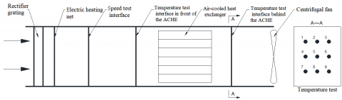
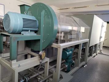
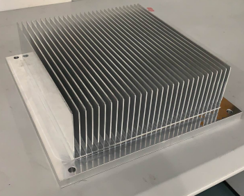
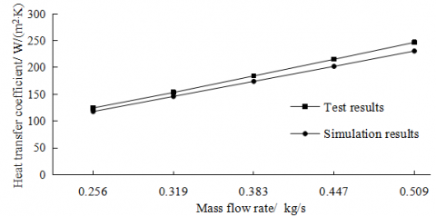
To verify the results of the numerical simulation in this paper, the IGBT air-cooled heat exchanger using the traditional straight-fin was tested. Figure 5 shows the schematic diagrams of the test device, the test bench, and the ACHE test piece. Then, the test data were compared with numeral simulation calculation results, as shown in Figure 6. It can be seen from the figure that the maximum deviation of the heat transfer coefficient between them was 6.5% and that of the outlet temperature was 5.35%, which are all within a reasonable range, proving the reliability of the numerical calculation results.
(a) Schematic diagram of test bench
(b) Test bench
(c) Test piece
Figure 5. Test Bench of the ACHE
(a) Heat transfer coefficient
(b) Outlet temperature
Figure 6. Comparison between numeral calculation results and test results
3.2 The influence of corrugation angle θ on heat transfer
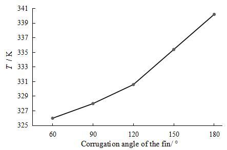
In order to explore the influence of the corrugation angle on the heat transfer and flow performance of the ACHE, the simulation calculation was conducted with the corrugation angle for 60°, 90°, 120°, 150°, and 180° respectively (when the angle θ reaches 180°, it means the traditional straight fin). Figure 7 shows that as the corrugation angle continues to increase, the maximum temperature of the IGBT baseplate increases significantly, indicating that the fin’s corrugation angle has an important influence on the heat transfer of the ACHE; at 120°, the slope of the curve has a certain transition, while the slope at 120°-180° is greater than that at 60°- 120°, indicating that the inclination angle of 120° is a key turning point. And the reduction of the corrugation angle will increase the flow resistance of air in the flow channel. Thus, further discussion and analysis was needed to determine the optimal corrugation angle.
Figure 7. The maximum temperature of IGBT baseplate under different fin corrugation angles
3.3 Temperature field analysis
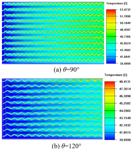
Figure 8 shows the nephograms of the temperature field in the ACHE, with the cross section at half the height of the vertical fin. It can be seen from the figure that the maximum temperature of the fin changes significantly with the corrugation angle. At 120°-180°, the reduction in the inclination angle can cause the maximum temperature to decrease from 57.1°C to 48.4 °C, indicating that the change of corrugation angle can strengthen the turbulent movement of the cooling air in the flow channel and increase the convective heat transfer to the fins; when the corrugation angle reached 90°, the maximum temperature rose instead, indicating that the corrugation angle can affect the fin temperature and the temperature field in the flow channel, but the angle cannot be too small. In view of this, only the corrugation angle of the fin between 90° and 180° was discussed in the following sections.
Figure 8. Nephograms of the temperature field in the ACHE under different fin corrugation angles
3.4 Comparison of Nusselt numbers between different models
Based on the calculation of the Reynolds number in the fin channel, the flow was found to be turbulent motion. According to the theory of heat transfer, the heat of the IGBT electronic device is transferred to the baseplate and fins by heat conduction, and the fins on the baseplate transfer the heat to the cooling air by convection heat transfer, so convective heat exchange is the main method used in the fin flow channel. The characteristic number of convective heat transfer can be obtained by the non-dimensionalization of the differential equation of convective heat transfer. The most important characteristic number is the Nusselt number, and its physical expression is shown in Eq. (9):
Figure 9. Comparison of Nu between different monitoring points under different fin corrugation angles
$Nu=\frac{hl}{{{\lambda }'}}$ (9)
where, h is the convective heat transfer coefficient (W/m2·K), l is the characteristic length (m), and λ’ is the thermal conductivity of the fluid (W/m·K). The Nusselt number can reflect the strength of convective heat transfer, especially the dependence relationship between related physical quantities and their comprehensive influence on convective heat transfer. For the turbulent heat transfer of the fluid in the pipe, if the temperature of the fluid and the wall surface are not much different, the Ditus-Bert formula [23] can be used:
$Nu=0.023R{{e}^{0.8}}P{{r}^{0.4}}$ (10)
where, Re and Pr are the Reynolds number and Prandtl number of airs respectively. It can be seen from Figure 9 above that among the four different fin models, the average Nu value with an angle of 120 degrees was the largest; on the cross-sections of the four monitoring points, the model with an angle of 120 degrees had the largest Nu number. Thus, the fin corrugation at this angle has the best convection heat transfer effect.
3.5 Analysis for pressure, turbulent kinetic energy and turbulent dissipation rate
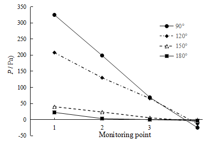
This paper focuses on the flow of cooling air in the corrugated flow field with the corrugation angle of the ACHE fins changing. Figure 10 shows the pressure changes in the flow field under different corrugated flow channels, in which the pressure of the traditional fin (straight fin corrugation angle of 180°) at each monitoring point didn’t change significantly; except for the monitoring point 1 in the inlet section, the pressure at other points was between -3 and 3Pa, and the pressure difference between the inlet and outlet was 25.3Pa. When the corrugation angle increased to 150°, the pressure difference between the inlet and outlet positions was 45.2Pa; when it reached 120°, the pressure difference increased obviously, up to 221.9Pa; when it’s 90°, the pressure difference reached 349.7Pa. Thus, the reduction of the inclination angle can significantly increase the flow resistance of the fluid in the ACHE, and the fin corrugation angle is an important inflection point at 120°.
Figure 10. The average cross-sectional pressure at the monitoring points under different fin corrugation angles
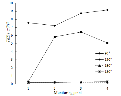
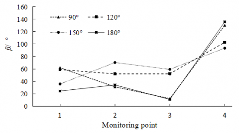
Figure 11 shows the average value of the fluid turbulent kinetic energy at each monitoring point. The date analysis found that the turbulent kinetic energy with a corrugation angle of 180° and 150° was not much different, and they were both less than 0.5m2/s2, indicating that the turbulent kinetic energy in the flow channel is small, and the fin structure does not influence the intensity of fluid turbulence. At the corrugation angle of 90°, the turbulent kinetic energy was greatly increased except for the position of the inlet section; at the angle of 120°, the turbulent kinetic energy at each point position was larger than that of other angles, and the average value of the cross section at thee point 4 increased about 29.6 times, which indicate that this structure plays a significant role in increasing the turbulent kinetic energy of the fluid; the corrugation angle is not negatively correlated with the turbulent kinetic energy.
Figure 11. The average turbulent kinetic energy at the monitoring points under different fin corrugation angles
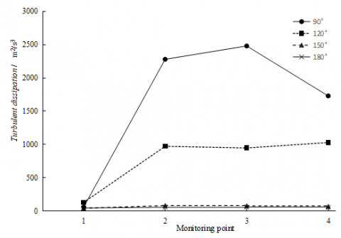
Figure 12 shows the calculation results of the fluid turbulent dissipation rate. It can be seen from the figure that the turbulent dissipation rate increased with the reduction of the corrugation angle θ, while it did not change much at 180° and 150°. At the point 1 of the inlet section, the turbulence dissipation rate with an angle θ of 120° was the largest compared to other angles, which reflects the enhancement effect of the inlet section on fluid flow; the average value at other monitoring positions reached the highest at 90°; at the 3-point cross section, the maximum turbulent dissipation rate was 39.5 times higher than that of the traditional fin structure, and the turbulent dissipation rate at an angle of 120° was 17.5 times higher than that of the traditional fin structure.
Figure 12. The average turbulent dissipation rate at the monitoring point under different fin corrugation angles
Through the field synergy analysis for the ACHE fins with different corrugation angles, this paper explores the influence of the gas flow channel structure generated by the corrugation angle on the field synergy.
4.1 Synergy analysis of velocity field and temperature field
According to literature [17], the general relationship between the Nusselt number of turbulent convective heat transfer and the local velocity field and temperature field is given as:
$Nu=RePr\int_{0}^{l}{\left( \overline{U}\cdot \nabla \overline{T} \right)}dY$ (11)
where, Nu,Re,Pr are Nusselt number, Reynolds number and Prandtl number respectively; $\bar{U}$ is the time average velocity; $\nabla \bar{T}$ is the time average temperature gradient.
The integrated factor can be expressed as:
$\overline{U}\cdot \nabla \overline{T}=\left| \overline{U} \right|\cdot \left| \nabla \overline{T} \right|\cos \alpha $ (12)
In Eq. (12) above, α is the angle between the velocity vector and the temperature gradient vector (heat vector). The physical meaning of this dimensionless integral is the sum of the intensity of the dimensionless heat source in the thickness section of the thermal boundary layer at x. Under certain conditions of velocity and temperature gradient, reducing the angle between them can achieve enhanced heat transfer. The synergy angle is expressed as:
$\alpha =\arccos \frac{\overline{U}\cdot \nabla \overline{T}}{\overline{\left| U \right|}\left| \nabla \overline{T} \right|}$ (13)
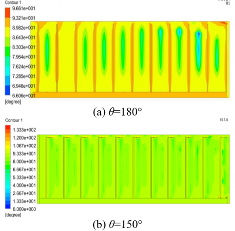
Figure 13. Nephograms of the synergy angle between the velocity and the temperature gradient at the monitoring point 3
Due to the limited length of the paper, Figure 13 only shows the nephograms of the synergy angle between the velocity and the temperature gradient at the monitoring point 3 section (away from the inlet and outlet position). It can be seen from the figure that as the fin corrugation angle θ decreased, the synergy angle between the velocity and the temperature gradient changed significantly. When using the straight fin (θ=180°), the distribution of θ at the monitoring point was very uneven, and there was a very obvious change gradient in the flow channel, indicating that the velocity and temperature gradient in the flow field are not stable enough, and the heat transfer effect in the channel is not the best; the comparison shows that when θ is equal to 150° and 120°, the synergy angles are uniformly distributed in the flow channel, and they’re less than 90°, indicating a significant heat transfer effect. Figure 14 shows a broken line graph of the average synergy angle between the velocity and the temperature gradient at different monitoring points in the flow channel with different fin angles θ. From this figure, it can be seen clearly that the average synergy angle of the straight fin was the minimum for 72° only on the cross section of point 1 at the inlet, and the average synergy angle at other flow field positions was not much different from 120°, but it fluctuated more obviously in the entire flow field; the average value α of the whole field was calculated to be 82° when using the straight fin; at θ=120°, the synergy angle in the entire field had the smallest fluctuation, indicating that the heat transfer enhancement effect in the entire flow field is more uniform than other angles, and the average value of the entire flow field α was 83.6°.
Figure 14. The average synergy angle of velocity and temperature gradient at each monitoring point
4.2 Synergy analysis between velocity and pressure gradient
For the enhanced convective heat transfer of the heat exchanger, it is generally necessary to increase the pump power or fan power. Considering the mutual coordination between the temperature field, pressure field, and velocity field of the heat medium in the heat exchanger, the heat exchange can also be enhanced by improving the synergy of the temperature field of the cold and hot fluid. According to the literature [17], the synergy relationship between velocity and pressure gradient is shown in (14):
$\overline{U}\cdot \left( -\nabla \overline{P} \right)=\left| \overline{U} \right|\left| -\nabla \overline{P} \right|\cos \beta $ (14)
Then, the synergy angle β can be derived as:
$\beta =\arccos \frac{\overline{U}\cdot \left( -\nabla \overline{P} \right)}{\left| \overline{U} \right|\left| -\nabla \overline{P} \right|}$ (15)
Based on the principle of field synergy, when $\bar{U} \cdot(-\nabla \bar{P})$ is constant, the smaller the β angle, the smaller the power consumption of the fluid.
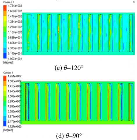
Figure 15. The average synergy angle of velocity and pressure gradient at each monitoring point
Figure 15 shows that except for the monitoring point 4 (the outlet position), the synergy angles at the other monitoring points were less than 90°; as the corrugation angle decreased, the synergy angle at each cross-section presents a more complicated change, indicating that the change of the corrugated angle has a greater impact on the flow resistance. Based on the average synergy angle β, it can be found that at 120°<θ<180°, the average synergy angle increases with the decrease of θ, indicating that the smaller the corrugation angle, the greater the flow resistance, but when it’s less than 120°, the influence of corrugation angle on the resistance is reduced. This is mainly because the reduction of the corrugation angle will decrease the size of its internal space, so that less fluid enters the angle space during fluid flow, and the resistance is also reduced.
It can be seen from Table 3 that based on the principle of field synergy, the smaller the synergy angle α, the stronger the fluid convection heat transfer; the smaller the synergy angle β, the smaller the fluid flow resistance; as the fin heat transfer coefficient changes with the corrugation angle, 120° is a demarcation point, i.e., at 180°~120°, the smaller the angle, the greater the heat transfer coefficient, while at less than 120°, the heat transfer coefficient decreases instead. When selecting the corrugation angle of 120°, the average β was increased by 29.6% compared with the traditional fin, and the heat transfer coefficient was by about 65%. This angle can not only achieve the purpose of strengthening convection heat transfer of the ACHE, but also avoid the large increase in the flow resistance.
Table 3. The average synergy angle and fin heat transfer coefficient of different corrugation angles
|
Corrugation angle θ(°) |
α Average value (°) |
β Average value (°) |
Heat transfer coefficients of fins (W/m2.K) |
|
90 |
90.7 |
58.9 |
50.8 |
|
120 |
83.6 |
66.5 |
52.9 |
|
150 |
78.9 |
64.7 |
42.4 |
|
180 |
82.1 |
51.3 |
32.1 |
(1) Using the CFD and field synergy methods, the simulation analysis was conducted for the internal flow field of the IGBT air-cooled heat exchanger in the EMUs, to obtain the synergy relationship between the temperature field, the velocity field and the pressure field, as well as the heat transfer coefficient, etc., and confirm the relevant characteristics of the ACHE.
(2) The pressure loss tends to increase with the decrease of the corrugation angle. At the corrugation angle between 120°~180°, the heat transfer capacity increases as the angle decreases, and at 120° it reaches the best heat transfer effect; at the corrugation angle less than 120°, the heat transfer capacity decreases as the angle decreases. The changes of the corrugation changes are related to the heat transfer coefficient and pressure loss, which should be taken into consideration to determine the best matching point according to actual needs.
(3) The corrugated fins change the flow channel structure. This structure increases the turbulent performance of the fluid in the ACHE by corrugation, thereby increasing the turbulent kinetic energy and turbulent dissipation rate of the fluid in the ACHE flow channel and improving the fluid heat exchange effect.
(4) The ACHE with corrugated fin structure was analyzed using the field synergy, to conclude that the change of the fin corrugation angle can significantly improve the degree of synergy between the speed field and the temperature field. At the corrugation angle of 120°, the average synergy angle α of the improved fin was increased by 2% compared with the traditional fin, and the heat transfer coefficient increased by 64.8%, indicating an enhanced effect of convection heat transfer; at the same time, the average synergy angle between the velocity field and the pressure field increased by 29.6%, and the flow resistance also increased. Through the comprehensive analysis, it’s found that the fin corrugation angle of 120° is conductive to achieving the purpose of enhancing the convective heat transfer effect without greatly increasing the flow resistance. It can be used as a design reference for such type of IGBT air-cooled heat exchanger.
Scientific research project of Liaoning Provincial Department of Education (Grant No.: JDL2019003).
[1] Hossain, M.Z., Rahim, N.A. (2018). Recent progress and development on power DC-DC converter topology, control, design and applications: A review. Renewable and Sustainable Energy Reviews, 81: 205-230. https://doi.org/10.1016/j.rser.2017.07.017
[2] Valenzuela, J., Jasinski, T., Sheikh, Z. (2005). Liquid cooling for high-power electronics. Power Electronics Technology, 31(2): 50-56.
[3] Wang, C.L., Ren, Z.Z., Zheng, Y.C., Ye, P.F., Zhang, K.F., Cui, X.W. (2019). Effects of heat treatment system on mechanical strength and crystallinity of CaO-MgO- Al2O3-SiO2 glass-ceramics containing coal gangue and iron ore tailings. Journal of New Materials for Electrochemical Systems, 22(2): 70-78. https://doi.org/10.14447/jnmes.v22i2.a02
[4] Han, C.W., Jeong, S.B. (2016). Evaluation of the thermal performance with different fin shapes of the air-cooled heat sink for power electronic applications. Journal of International Council on Electrical Engineering, 6(1): 17-25. https://doi.org/10.1080/22348972.2015.1115168
[5] Focke, W.W., Zachariades, J., Olivier, I. (1985). The effect of the corrugation inclination angle on the thermohydraulic performance of plate heat exchangers. International Journal of Heat and Mass Transfer, 28(8): 1469-1479. https://doi.org/10.1016/0017-9310(85)90249-2
[6] Zhang, J., Wen, J., Zhao, L. (2015). Heat transfer and flow analysis and corrugation parameters optimization of the plate heat exchanger based on computational fluid dynamics numerical simulation. Journal of Mechanical Engineering, 51(12): 137-145. https://doi.org/10.3901/JME.2015.12.137
[7] Wang, X., Ma, B.L., Chen, M.Y., Xin, L. (2012). Thermal design and experimental research on high-power IGBT module heatsink applied in rail vehicle. Electric Drive for Locomotives, 2012(4): 71-73. https://doi.org/10.3969/j.issn.1000-128X.2012.04.020
[8] Liu, Z.C., Liang, X.F., Quan, G.H., Zhong, M., Xiong, X.H. (2017). Ventilation and heat dissipation for high-speed train traction transformer. Journal of Central South University (Science and Technology), 48(11): 3127-3132. https://doi.org/10.11817/j.issn.1672-7207.2017.11.037
[9] Liu, J.C., Zhang, S.Y., Zhou, Z.Y. (2014). Analysis of channel structure improvement and its influence on fluid flow in plate-fin heat exchanger. Journal of Mechanical Engineering, 50(18): 167-176. https://doi.org/10.3901/JME.2014.18.167
[10] Şahin, B., Akkoca, A., Öztürk, N.A., Akilli, H. (2006). Investigations of flow characteristics in a plate fin and tube heat exchanger model composed of single cylinder. International Journal of Heat and Fluid Flow, 27(3): 522-530. https://doi.org/10.1016/j.ijheatfluidflow.2005.11.005
[11] Li, X.Y., Li, Z.H., Tao, W.Q. (2018). Experimental study on heat transfer and pressure drop characteristics of fin-and-tube surface with four convex-strips around each tube. International Journal of Heat and Mass Transfer, 116: 1085-1095. https://doi.org/10.1016/j.ijheatmasstransfer.2017.09.076
[12] Navaneethakrishnan, B., Nithyanandan, N., Adalarasan, R., Santhanakumar, M., Kumar, P.S.M. (2018). Optimal performance evaluation of energy efficient residential air conditioning system with nanofluid-based intercooler using Taguchi-based response surface methodology. Journal of New Materials for Electrochemical Systems, 21(3): 141-150. https://doi.org/10.14447/jnmes.v21i3.455
[13] Chen, Q., Fu, R.H., Xu, Y.C. (2015). Electrical circuit analogy for heat transfer analysis and optimization in heat exchanger networks. Applied Energy, 139: 81-92. https://doi.org/10.1016/j.apenergy.2014.11.021
[14] Zhang, Z.B., Zhang, H., Liu, Y., Zheng, K.Q., Xu, Z.M. (2017). Numerical simulation and field synergy principle analysis on the characteristic for new distribution region of heat exchanger. Journal of Mechanical Engineering, 53(6): 145-151. https://doi.org/10.3901/JME.2017.06.145
[15] Wang, Z., Li, Y.Z. (2016). Multi-object tradeoff optimization of heat transfer and fluid friction for plate-fin heat exchanger. Journal of Engineering Thermophysics, 37(2): 399-404.
[16] Cao, X., Du, W.J., Cheng, L. (2012). Analyses on flow and heat transfer performance and entropy generation of heat exchanger with continuous helical baffles. CIESC Journal, 63(8): 2375-2382. https://doi.org/10.3969/j.issn.0438-1157.2012.08.006
[17] Li, Z.X., Guo, Z.Y. (2016). Field Synergy Theory for Convective Heat Transfer Optimization. BeiJing, Science Press.
[18] Shen, J., Zeng, L., Liu, Z., Liu, W. (2019). Performance investigation of PEMFC with rectangle blockages in Gas Channel based on field synergy principle. Heat and Mass Transfer, 55(3): 811-822. https://doi.org/10.1007/s00231-018-2473-5
[19] Zeng, M., Tao, W.Q. (2004). Numerical verification of the field synergy principle for turbulent flow. Journal of Enhanced Heat Transfer, 11(4): 451-457. https://doi.org/10.1615/JEnhHeatTransf.v11.i4.220
[20] Liu, W., Liu, Z.C., Ma, L. (2012). Physical quantity application of a multi-field synergy principle in the performance evaluation of convective heat transfer enhancement in a tube. Chinese Science Bulletin, 57(10): 867-874. https://doi.org/10.1007/s11434-012-5062-x
[21] Yakhot, V., Orszag, S.A. (1986). Renormalization group analysis of turbulence. I. Basic theory. Journal of Scientific Computing, 1(1): 3-51. https://doi.org/10.1007/BF01061452
[22] Schlichting, H., Gersten, K. (2016). Boundary-Layer theory. Springer.
[23] Tao, W.Q. (1998). Numerical Heat Transfer. Xi'an: Xi'an Jiaotong University Press.