Amal Abass | Rami Y. Dahham* | Dhirgham Alkhafaji
© 2020 IIETA. This article is published by IIETA and is licensed under the CC BY 4.0 license (http://creativecommons.org/licenses/by/4.0/).
OPEN ACCESS
This paper focuses on the studying behavior of velocity profile with the influence of different temperatures for the inner and outer annulus of can combustor. An experimental rig was designed to simulate the flow inside the annulus of can combustor. An analytical CFD tool was designed and validated with experimental data. The can combustor tested in this study is a real part collected from Hilla/Iraq gas turbine power station. The velocity profiles are investigated in six stations in the annulus region. The axial velocity and turbulence intensity are calculating with a different temperature for inner and outer annulus. From The results, the increase in temperature leads to undesirable reversible flow and large recirculation zone. It is found that high turbulent intensity leads to destroy the cooling film. The increasing temperature would increase the turbulence intensity causing a recirculation region enlargement. The results also show that the high temperature, velocity profile and the jet of air through holes. The Computational results were compared against the experimental results, and they show a very good agreement.
annulus airflow, velocity profile and rising temperatures of liner wall, gas turbine combustor
A can combustor is a main part of a gas turbine power unit which draws the air from a compressor and transmits it to the turbine with a high temperature. In general, the combustor has three main components: diffuser, casing, liner and inner and outer annulus as shown in Figure 1 [1]. The airflow in can combustor is separated to three parts. The first part of the airflow passes through the dome (front end of combustor). This part of the air is used to cool dome and to be mixed with fuel injected by the nozzles. The second and third parts of airflow passing through the inner and the outer annulus where the study focused on these parts [2].
Hasan and Puthukkudi [3] investigated the effusion film cooling method on an adiabatic flat plate. The CFD result showed that there is a relationship between film cooling effectiveness and velocity ratio. The study showed the velocity ratio effected on mass flow rate. A high mass flow rate works to increase effectiveness. This lead to create a large demand on cold air where that will effect on the efficiency of the gas turbine. Gomez Ramirez et al. [4] studied the flow field properties into the annular combustor gas turbine with radial swirls. The heat transfer coefficient increased with increasing Reynolds numbers. Kumar and Rose [5] studied the influence of changes in the coefficient of the heat transfer on the distribution temperature profile at the inner and outer liner surface. The height coefficient led to raise the heat transferred and rise wall temperatures. Liu and Zheng [6] studied the effusion cooling. The temperature of the wall and the effectiveness of film cooling for different angles were analyzed. The performance of the effusion cooling was better than the conventional film cooling.
The wall temperature was lower, the efficiency of the cooling was higher and the coolant was decreased by 20%. The performance of cooling for deflection angle 60° was best. Mohammed et al. [7] investigated the characteristics of the heat transfer in the can combustor of the gas turbine with Reynolds number 50,000 and 600,000 and a swirl number of 0.7. The size of recirculation zone near the liner wall stayed at same for all Reynolds numbers.
Figure 1. The components of combustor
The previous studies offered combustor cooling method, design combustor, pressure loss with range of operating conditions, the behavior of distributions heat transfer and flow filed with different angle swirl, the influence front flame on the flow inside of the combustor and air to fuel ratio on distribution temperature in the primary zone. This research will study the behaviors flow fields inside annulus region of can combustor with rising liner temperature from (298K-773K). The flow field in magnitude directions will analyze to explain the back flow with rising temperature. The relationship between velocity profile and wall temperature of the inner and outer annulus in the can combustor are investigated experimentally and numerically [8, 9].
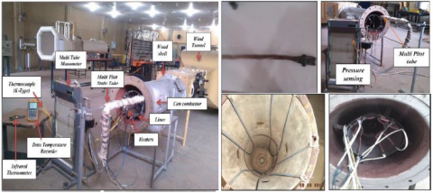
Before starting to measure the velocity at the annulus region, the rig was designed as the procedure below. Figure 2 was showed the rig that used at experimental work.
(1) The can combustor was connected to the wind tunnel. The air was transmitted from the wind tunnel to the front end of the combustor.
(2) The liner wall was heated by using four cylindrical heaters (3000W).
(3) The temperature of the liner wall was measured by using six thermocouples. These thermocouples were fixed on the outer liner wall.
(4) The time was used to warm up the heaters about 2.5 hours.
(5) After then, the multi pitot-tube moved horizontally through the annulus of can combustor and measured the velocity profile in the annulus region at six stations.
For accuracy of results in the experimental work, calibration of the rig measuring devices was done by using calibration instruments. The multi pitot-tube was calibrated with L-shape pitot-static tube with airflow at environment temperature. The error in reading was about 5.5%. Also, thermocouple and Infrared thermometer were calibrated with a thermometer at hot surface and record reading after every two minutes. The error in reading thermocouple was about 2.3% and the Infrared thermometer was about 4.2%.
(a) The rig that used in experimental work
(b) Schematic diagram of rig design
(c) The casing and the liner of can combustor
(d) Schematic diagram of multi pitot-tube
Figure 2. Experimental work
A commercial obtainable computational fluid dynamics (CFD) code “ANSYS-FLUENT 16.0” was used for the analysis. A combustion model was created from 3-D geometry using SolidWorks 2016 software. The CAD model has been imported to “ANSYS-FLUENT 16.0” to achieve the proper mesh by choosing the relevant center is fine, smoothing (high), transition (fast) and span angle center (fine). The boundary conditions have been set. Table 1 showed the dimension of this geometry. The type of mesh was Tet/hybrid and the number of mesh cells is 1028782 as shown in Figure 3. The boundary condition was defined in Table 2.
Table 1. Dimensions of can combustor
|
Casing diameter |
410 mm |
Holes number |
|
Liner diameter |
280 mm |
|
|
Casing length |
1060 mm |
|
|
Liner length |
1020 mm |
|
|
Dome holes diameter |
8.2 mm |
96 |
|
Primary holes diameter |
19.5 mm |
8 |
|
Secondary holes diameter |
19.5 mm |
8 |
|
Dilution holes diameter |
40 mm |
4 |
Table 2. Boundary condition
|
Inlet velocity |
32 m/s |
|
Outlet |
Flow outlet |
|
Temperature of air flow inlet |
298 K |
|
Turbulence intensity |
5% |
|
Residual error |
1x 10⁻⁷ |
|
Model |
RNG |
|
Temperature of liner wall |
|
|
Case one |
298 K |
|
Case two |
473 K |
|
Case three |
523 K |
|
Case four |
573 K |
|
Case five |
673 K |
|
Case six |
773K |
Figure 3. Computational meshed model (Tet/hybrid)
3.1 The governing equations for RNG Model [10-16]
k-equation
$\begin{array}{c}
\rho \frac{D k}{D t}=\frac{\partial}{\partial x j}\left[\left(\mu+\frac{\mu_{t}}{\sigma_{t}}\right) \frac{\partial k}{\partial x j}\right]+\mu_{t} s^{2}-\rho \varepsilon-g_{i} \frac{\mu_{t}}{\rho p_{r_{k}}} \frac{\partial \rho}{\partial x j} \\
-2 \rho \varepsilon \frac{k}{\gamma R T}
\end{array}$ (1)
where, p is pressure, ρ is density and xj is the uj-direction velocity component.
Ɛ-equation
$\rho \frac{D \varepsilon}{D t}=\frac{\partial}{\partial x j}\left[\left(\alpha_{\tau} \mu_{e f f}\right) \frac{\partial \varepsilon}{\partial x j}\right]+\frac{\varepsilon}{k}\left(C_{1 \tau} \mu_{\tau} s^{2}-\rho \varepsilon C_{2 \tau}^{*}\right)$ (2)
Continuity equation:
$\frac{\partial \rho}{\partial t}+\frac{\partial\left(\rho u_{j}\right)}{\partial x_{i}}=0$ (3)
$\text { where, } C_{1 \tau}=1.42, C_{2 \tau}=1.68, C_{\mu}=0.0845$
$C_{2 \tau}^{*}=\mathrm{C}_{2 \tau}+\left(\left(c_{\mu} \rho \eta^{3}\left(1-\eta_{1} / \eta_{0}\right)\right) /\left(1+\beta \eta^{3}\right)\right)$ (4)
$S_{i j}=(1 / 2)\left(\frac{\partial u_{i}}{x_{j}}+\frac{\partial u_{j}}{x_{i}}\right)$ (5)
where, $S_{i j}$ is the rate of tensor, and eddy viscosity $\mu_{t}$ is defined as:
$\mu_{t}=\rho c_{\mu}\left(\frac{k^{2}}{\varepsilon}\right)$ (6)
Also, $c_{\mu}$ is a constant, $k$ is turbulence kinetic energy and $\varepsilon$ denotes turbulence kinetic energy dissipation rate.
3.2 Air properties and boundary conditions
The combustion chamber is the test section where the aerodynamic behavior inside the combustor has been simulated. Before beginning with the simulation, the FLUENT must be provided with the former prediction for the solution flow field. Forewarn must be taken when supply the initial steps to allow the desired final solution to be attained.
The air is the fluid, which is used in this project, so the properties of air are taken at atmospheric pressure and temperature 298 K, as shown in Table 3.
Table 3. Air properties
|
ρ |
1.1774 |
kg/m3 |
|
Cp |
1005.7 |
J/(kg .K) |
|
k |
0.02624 |
W/(m. K) |
|
µ |
1.8462*10-5 |
kg/m. s |
3.3 Grid dependency
Most computational domain needs increasing the number of grids to improve the numerical results. The achievement of the optimum number of grids as shown in Figure 4 has been depicting temperature variation along the radial distance of the combustor at the axial distance of 0.2 m from the inlet for different grid numbers. When the number of grids is increasing larger than 1238989 do not bring about a significant improvement, thus, 1028782 cells are considered to minimize the computation time and cost.
Figure 4. Temperature variation along the radial distance of the combustor for different cell numbers
4.1 Model validation
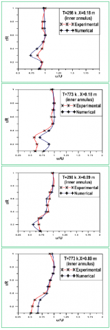
CFD was used in this study to investigate the properties of airflow in the annulus region. It was necessary to validate the CFD program before it was used as a tool of study. The validation was done by comparing the CFD results with experimental results and tabulated in Table 4. The comparison depends on velocity at the inner annular as shown in Figure 5.
Figure 5. Magnitude velocity profile at two stations for different temperature in the inner annulus of can combustor
The velocity profiles at T=298 K have dropping velocities near the liner wall which affect negatively on penetration air through the liner holes. The maximum percentage error between the experimental and numerical (CFD) results was about ±6%. The dropping velocity increased at T=773 K. This phenomenon occurred due to the high heat transfer to annulus airflow. There was an acceptable agreement between the experimental and the numerical results about ±7%.
At the last station (X=0.89m) with T=298 K, the validation was agreement about error max ±4% that may be due to the easy control on multi pitot-tube. The comparison between experimental results and numerical results at T=773 K was increased by about 5.7%.
Table 4. Percentage error comparing the CFD results with experimental results
|
X=0.18 m (inner annulus) |
Percentage error % |
|
T=298 K |
6% |
|
T=673 K |
7% |
|
X=0.89 m (inner annulus) |
Percentage error % |
|
T=298 K |
4% |
|
T=673 K |
5.7% |
4.2 The behavior of velocity profile in the annulus region
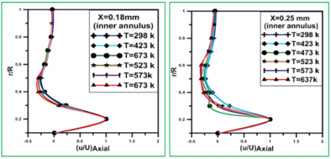
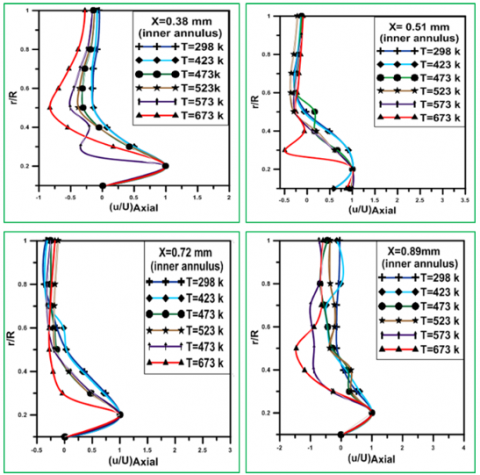
Figure 6, shows the behavior of velocity profile in annulus region at T=773 K. When the temperature rises the dropping velocities will be increased. The rising temperatures led to increasing the heat transfer to air layers near the liner wall. This dropping increased when the temperature increased about (8%-33%), where the temperature increasing led to increase in viscous of air due to increase in the activity molecular. The slow layers entered the fast layers and tended to decelerated fast layers. The dropping of velocities has negatively affected on the penetration air through the holes.
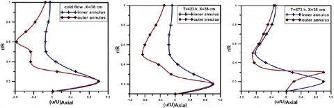
4.3 Axial velocity in the inner annulus
The computational analysis results were showed that the reversible flow is directly proportional to temperature. It can be seen at Figure 7, the reversible profile shows more backflow when the temperature is around T=673 K than with T=423 K. The reversible flow for different temperatures may be due to the heat transferred from liner wall to the airflow in the annulus.
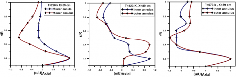
4.4 Axial velocity profile in the inner and outer annulus
The velocity profiles at station one (X=0.18m) have almost the same trend in both of the inner and outer annulus. This behavior may be due to the lower transferred heat to the airflow in the annulus at this station as shown in Figure 8(a). Figure 8(b) It can be seen that, the axial velocity is higher in the inner annulus at the third station (X=0.38m) than the outer annulus which may be due to the higher heat transfer and the effect of gravity which accelerates the flow in the inner annulus. Figure 8(c), shows unstable behavior in the velocity profile with the temperature increase in both inner and outer annulus. However, the inner velocity is still higher than the outer velocity due to the gravity effect. The oscillation of axial velocity profile at station six (X=0.89m) is due to the increase the heat transfers at this station.
Figure 6. The behavior of velocity profile at outer annulus region of can combustor at T=773 K
Figure 7. Axial velocity in inner annulus for different temperature
(a)
(b)
(c)
Figure 8. Axial velocity at the inner and outer annulus (a) station one (X=0.18m); (b) station three (X=0.38m) and (c) station six (X=0.89m)
(a)
(b)
Figure 9. (a) Turbulent intensity contour at first station with T=298 K, 673 K and 773 K; (b) Turbulent intensity contour at fourth station with T=298 K, 673 K and 773 K
4.5 The turbulent intensity of annulus
The turbulent flow in the annulus has a high effect on the velocity profile. The turbulent intensity increased with temperature rise as shown in Figures 9(a) and (b), these figures show contours of turbulent intensity in the first station (X=0.18m) and the fourth station (X=0.51m). At the first station, the turbulent intensity near the liner wall changed from 128 at T=298 K to 197 at T=773 K. The different turbulent intensity distribution occurs due to the different temperatures in the annulus as well as an increase in average magnitude of turbulence is due to the interaction of multiple jets with the swirling cross-flow in the liner.
The analysis of annulus flow by axial velocity show the deep affected on pattern flow in annulus. The rising of temperature lead to destroy the velocity profile in annulus which led to undesirable reversible flow and large recirculation zone. The inner velocity is still higher than the outer velocity due to the gravity effect. A turbulent intensity affected on temperature and velocity profile. High turbulent intensity led to destroy cooling film, high temperature, and different velocity profile.
This work was supported by the University of Babylon/ Mechanical Engineering department for the use of their facilities. The authors would also like to show their gratitude to the Gas Generating Station Staff ministry of electricity of Iraq for their assistance in carrying out this work.
|
Cp |
specific heat, J/ (kg K) |
|
g |
gravitational acceleration, m. s-2 |
|
k |
thermal conductivity, W/m.K |
|
Nu |
local Nusselt number along the heat source |
|
u |
velocity (m/s) |
|
A |
area(m2) |
|
D |
diameter, m |
|
P |
pressure, N/m2 |
|
R |
radius of combustor, m |
|
T |
temperature, K |
|
Greek symbols |
|
|
ε |
turbulence kinetic energy dissipation m2/s3 |
|
δ |
kronecker delta |
|
ρ |
density kg/ m3 |
|
k |
turbulence kinetic energy m2/s2 |
|
a |
thermal diffusivity, m2. s-1 |
|
b |
thermal expansion coefficient, K-1 |
|
µ |
dynamic viscosity, kg. m-1.s-1 |
|
ʋ |
kinematic viscosity m2/s |
|
I |
turbulent Intensity % |
|
$\mu_{\mathrm{t}}$ |
turbulent viscosity kg/m.s |
|
$\mu_{\text {eff }}$ |
effective viscosity |
|
σw2 |
turbulent Prandtl numbers |
|
$\alpha_{\tau}$ |
inverse prandtl number |
|
$\sigma_{\mathrm{k}} \sigma_{\varepsilon} \mathrm{C}_{\varepsilon 1} \mathrm{C}_{\varepsilon 2} \mathrm{C}_{\mu}$ |
constant |
[1] Alqaraghuli, W., Alkhafagiy, D., Shires, A. (2014). Simulation of the flow inside an annular can combustor. International Journal of Engineering and Technology, 3(3): 357-364. http://dx.doi.org/10.14419/ijet.v3i3.2499
[2] Sridhara, S.R., Tejaas, V.R., Kumar, V., RK, N. Automotive-turbocharger based gas turbine engine used to produce electricity. International Journal of Scientific and Research Publications, 6(8): 146-174.
[3] Hasan, R., Puthukkudi, A. (2013). Numerical study of effusion cooling on an adiabatic flat plate. Propulsion and Power Research, 2(4): 269-275. https://doi.org/10.1016/j.jppr.2013.11.002
[4] Gomez Ramirez, D., Kumar, V., Ekkad, S., Tafti, D., Kim, Y.W., Moon, H.K.X., Srinivasan, R. (2014). Flow field and liner heat transfer for a model annular combustor equipped with radial swirlers. In 50th AIAA/ASME/SAE/ASEE Joint Propulsion Conference, Cleveland, OH, pp. 3436. https://doi.org/10.2514/6.2014-3436
[5] Kumar, G.M., Rose, J.B.R. (2015). Numerical comparative study on convective heat transfer coefficient in a combustor liner of gas turbine with coating. International Journal of Mechanical Engineering and Research, 5(1): 14-19.
[6] Liu, X., Zheng, H. (2015). Influence of deflection hole angle on effusion cooling in a real combustion chamber condition. Thermal Science, 19(2): 645-656. https://doi.org/10.2298/TSCI140107043L
[7] Mohammed, S., Khalil, E. E., Hariedy, H., Bially, E. (2015). Heat transfer and flow chrecterictics in a gas turbine can combustor: Turbulent interaction. In 51st AIAA/SAE/ASEE Joint Propulsion Conference, Orlando, FL, pp. 4094. https://doi.org/10.2514/6.2015-4094
[8] Stitzel, S., Thole, K.A. (2004). Flow field computations of combustor-turbine interactions relevant to a gas turbine engine. Journal of Turbomach., 126(1): 122-129. https://doi.org/10.1115/1.1625691
[9] Celik, I.B. (1999). Introductory Turbulence Modeling. Western Virginia University Class Notes. N.p., 94.
[10] Fluent Inc (February 2003). FLUENT 6.1 User's Guide.
[11] Kwark, J.H., Jeong, Y.K., Jeon, C.H. and Chang, Y.J., (2005). Effect of swirl intensity on the flow and combustion of a turbulent non-premixed flat flame. Flow, Turbulence and Combustion, 73(3): 231-257. https://doi.org/10.1007/s10494-005-4777-z
[12] Yoon, J., Kim, M.K., Hwang, J., Lee, J., Yoon, Y. (2013). Effect of fuel–air mixture velocity on combustion instability of a model gas turbine combustor. Applied Thermal Engineering, 54(1): 92-101. https://doi.org/10.1016/j.applthermaleng.2013.01.032
[13] Nagano, Y., Tagawa, M., and Tsuji, T. (1993). Effects of adverse pressure gradients on mean flows and turbulence statistics in a boundary layer. In Turbulent Shear Flows, 8: 7-21. https://doi.org/10.1007/978-3-642-77674-8_2
[14] Innocenti, A., Andreini, A., Facchini, B. (2015). Numerical identification of a premixed flame transfer function and stability analysis of a lean burn combustor. Energy Procedia, 82: 358-365. https://doi.org/10.1016/j.egypro.2015.11.803
[15] Dahham, R.Y., Alkhafaji, D., Al-Jelawy, H., Hadi, S.J. (2018). Experimental and numerical study of the effect of vibration on airflow between can combustor liner and casing. Instrumentation Mesure Métrologie, 17(2): 235-257. https://doi.org/10.3166/I2M.17.235-257
[16] Mousavi, S.E., Kheradmand, S., Mirzabozorg, M.A.S. (2019). Effect of oscillating inlet flow on combustion instability. International Journal of Heat and Technology, 37(4): 1080-1088. https://doi.org/10.18280/ijht.370417