Xiaoyong Peng | Haidong Jiang*
© 2020 IIETA. This article is published by IIETA and is licensed under the CC BY 4.0 license (http://creativecommons.org/licenses/by/4.0/).
OPEN ACCESS
This paper aims to develop suitable formulas of the drilling fluid for slow angle wireline core drilling. Firstly, the materials and properties of drilling fluid were analyzed in details. Then, three kinds of drilling fluids were prepared, namely, those with low-solid phase mud, those with no-solid phase mud, and those with weighted mud. After that, a total of forty drilling tests were carried out using each type of drilling fluids. The average coring rate was as high as 87%. Based on the test results, the drilling fluid formulas for slow angle wireline core drilling were optimized as follows: original mud + 4.5% cellulose + 5% potassium humate + 4.5% high-efficiency water loss reducer + 6% multi-effect plant gum SD-2 + 5% type 06 lubricant + water for relatively complete strata; original mud + 0.75% cellulose + 2% potassium humate + 2% multi-effect plant gum SD-2 + 5% type 06 lubricant + water for broken and collapse-prone strata; original mud + 0.75% cellulose + 5% potassium humate + 2% multi-effect plant gum SD-2 + 5% type 06 lubricant + 10% barite + water for high-pressure strata. The research results provide a good reference for drilling fluid preparation in slow angle wireline core drilling.
drilling fluid, formula, admixture, rheology, low-solid phase, no-solid phase
Water-based drilling fluid system was invented nearly 100 years ago [1-3]. In the 1930s, many patented silicate drilling fluids appeared in the US, which were proved effective in preventing borehole instability [4-7]. In the early 1960s, US engineers started to replace caustic soda with silicate as an additive to adjust the pH of drilling fluid, with the aim to stabilize shale and thus the borehole [8-13]. In the 1980s, liquid silicate and partially hydrolyzed polyacrylamide were adopted as shale stabilizers in China [13-16]. Since then, various formulas have been prepared for silicate drilling fluid around the world, bringing many silicate-containing compound drilling fluid systems capable of reducing viscosity and water loss [17-19].
Currently, wireline core drilling uses three types of mud, namely, no-solid phase mud (water-based mud), no-dispersion low-solid phase mud, and special mud [20, 21]. The type and performance parameters of mud need to be selected based on the target stratum.
If the target stratum is relatively complete, no-solid phase mud should be selected for drilling. The no-solid phase mud, containing no clay, is prepared by adding chemical treatment agents into water. This kind of mud is an improved version of low-solid phase mud, and adaptive to the drilling requirements. The no-solid phase mud excels over water in lubricity and drag reduction, and boasts lighter specific gravity, more flexible viscosity, better fluidity, and fewer solid phases than pure mud. Hence, this kind of mud can greatly improve the rock-breaking efficiency of the drill bit at bottom hole [22].
There are six kinds of no-solid phase mud: (1) synthetic polymer solutions, e.g. partially hydrolyzed polyacrylamide (HPAM), hydrolyzed polyacrylonitrile (HPAN), and PAV; (2) cellulose solutions, e.g. carboxymethyl cellulose (CMC) and hydroxyethyl cellulose (HEC); (3) wild plant gum solutions, e.g. konjac and sesbania; (4) biopolymer solutions, e.g. Xanthan gum (XC) biopolymers; (5) inorganic salt gel solutions, e.g. sodium silicate gel solution; (6) surfactant solutions, e.g. lubricating flushing solution.
If the target stratum is relatively fractured, the non-dispersion low-solid phase mud (4% clay) should be selected for drilling. This kind of mud mainly consists of clear water, high-quality bentonite, chemical flocculant, and water reducing agent. The polyacrylamide mud, a popular choice for wireline core drilling with diamond bit, is a non-dispersion low-solid phase mud. The polyacrylamide is a selective flocculant capable of retaining high-quality mud-making clay, while removing poor-quality rock powder, because its flocculation ability varies from bentonite to rock powder. The polyacrylamide mud is mainly made of polyacrylamide treatment agent, plus a suitable amount of water loss reducer. The mix ratio between polyacrylamide and water can be adjusted as per the drilling conditions.
To optimize the drilling fluid formulas for slow angle wireline core drilling, this paper firstly examines the materials and properties of drilling fluid, and then prepared three kinds of drilling fluid systems based on low-solid phase mud, no-solid phase mud, and weighted mud, respectively. Through field tests on the three systems, the optimal drilling fluid formulas were obtained for slow angle wireline core drilling in complete, broken, and high-pressure strata, respectively.
To prepare a universal drilling fluid, chemical treatment must be implemented in addition to selecting a proper clay. The treatment includes the primary treatment during mud-making, and the supplementary treatment during drilling.
During primary treatment, chemical agents are added to help clay particles disperse or flocculate moderately, creating drilling fluid whose performance indices meet the drilling requirements.
During the supplementary treatment, the performance of drilling fluid is adjusted to meet the drilling requirements by adding chemical treatment agents. The adjustment measures include: reducing water loss, enhancing/weakening viscosity and shear force, lowering viscosity and shear force, increasing/reducing specific gravity, preventing leakage, promoting flocculation, to name but a few.
2.1 Selection of clay
With good mud-making effect and stability, bentonite is generally selected to improve drilling efficiency. The clay content in the drilling mud must be controlled to minimize the solid phase content.
2.1.1 Originally used clay
The original mud produced by Jinchuan Group Co., Ltd. was subjected to tests on materials, mud yield, water loss, and performance. The original mud was mainly prepared with two kinds of poor-quality kaolinite clays: laterite blocks and carclazyte powders. With a high sand content, these clays have a low mud yield. The original mud is not viscous enough for normal drilling, as the clay content is no greater than 20%. During wireline core drilling, the original mud often leaves a mud skin on the inner wall of the drill pipe, making it difficult to lower the inner pipe.
According to the test results on mud yield, water loss, and performance, the laterite blocks could not function properly as mud clay, and should not be used for drilling; the carclazyte powders are featured by a low mud yield, high water loss, and a high sand content.
2.1.2 Clay selection
To improve the original clay, the properties of clay materials and alkali dosages were tested in turn, see table1.
(1) Basic performance tests
Four clay samples were prepared according to the following mix ratios: water + 6% sodium soil; water + 6% calcium soil; water + 6% attapulgite; water + 6% Shandong bentonite. Each sample was stirred for 20min, pre-hydrated for 24h, and then stirred for another 20min. The samples were subjected to basic performance tests. The test results (Table 2) show that the addition of alkali could improve the dispersibility and colloid fraction of ordinary mud-making clays.
To test the dispersion stability of drilling mud, sample 1 (water + 6% sodium soil) was treated by four different dosages of soda: water + 6% sodium soil + 0% soda; water + 6% sodium + 0.03% soda; water + 6% sodium + 0.06% soda; water + 6% sodium + 0.12% soda. Each sample was stirred for 10min before pH measurement, and let stand for 24h before colloid fraction measurement.
Table 1. Test results on original mud
|
Serial number |
Name of mud |
Mud ratio |
Treatment agent |
Mix ratio (g/cm3) |
Funnel viscosity (s) |
Water loss (mL/7.5min) |
|||
|
Type |
Weight (g) |
Water (mL) |
Name |
Dosage (g) |
|||||
|
1 |
Original mud |
Laterite block |
150 |
1,000 |
Na2CO3 |
3 |
1.10 |
15.6 |
28 |
|
2 |
Original mud |
Laterite block |
200 |
1,000 |
Na2CO3 |
4 |
1.12 |
15.8 |
20 |
|
3 |
Original mud |
Laterite block |
250 |
1,000 |
Na2CO3 |
5 |
1.13 |
16.0 |
9 |
|
4 |
Original mud |
Carclazyte powders |
80 |
1,000 |
Na2CO3 |
4 |
1.05 |
15.1 |
20 |
|
5 |
Original mud |
Carclazyte powders |
100 |
1,000 |
Na2CO3 |
4 |
1.06 |
15.2 |
25 |
|
6 |
Original mud |
Carclazyte powders |
120 |
1,000 |
Na2CO3 |
4 |
1.07 |
15.4 |
21 |
Table 2. Basic performance of clay samples
|
Test number |
Ф600 |
Ф300 |
Ф200 |
Ф100 |
YP |
$\frac{\tau_{d}}{\eta_{p}}$ |
pH |
Colloid fraction |
Remarks |
|
1 |
4 |
1.9 |
1.6 |
0.7 |
- |
- |
8 |
100 |
About 3mL precipitation at the bottom |
|
2 |
7.3 |
4.3 |
2.9 |
1.7 |
0.65 |
0.221 |
6 |
7 |
Separation between soil and water |
|
3 |
13.6 |
11.3 |
10.4 |
9.2 |
4.5 |
2 |
6 |
100 |
|
|
4 |
15 |
10 |
8.6 |
6.4 |
2.5 |
0.511 |
6 |
7 |
Separation between soil and water |
Next, sample 2 (water + 6% calcium soil) was treated by five different dosages of soda: water + 6% calcium soil + 0% soda; water + 6% calcium soil + 0.12% soda; water + 6% calcium soil + 0.18% soda; water + 6% calcium soil + 0.24% soda; water + 6% calcium soil + 0.3% soda. The samples were processed and measured similarly as above.
The test results (Tables 3 and 4) show that adding a proper amount of soda could improve the dispersibility and stability of soil powder in water. The sodic soil is slightly alkaline, with a high colloid fraction. But there were a few precipitations at the bottom. After soda was added, the sodium soil dispersed more uniformly with a high colloid fraction, and no precipitation was observed at the bottom. With the growing alkali dosage, the colloid fraction and stability of calcium soil were improved. The soda dosage should be 4% to ensure the performance of drilling mud. The above results confirm that the bentonite content of 3-5% could meet the requirements on mud-making. The mud thus prepared contains no polyacrylamide and does not lead to flocculation.
Table 3. pH and colloid fractions of sample 1 after soda treatment
|
Test number |
pH |
Colloid fraction |
Remarks |
|
5 |
7 |
90 |
About 3mL precipitation at the bottom |
|
6 |
7.5 |
90 |
About 1mL precipitation at the bottom |
|
7 |
8 |
95 |
|
|
8 |
9 |
95 |
|
Table 4. pH and colloid fractions of sample 2 after soda treatment
|
Test number |
pH |
Colloid fraction |
Remarks |
|
9 |
6 |
88 |
About 3mL precipitation at the bottom |
|
10 |
7.5 |
90 |
About 2mL precipitation at the bottom |
2.2 Alkali treatment of clay
The pH, which directly bears on the performance of drilling fluid, is an important indicator in the chemical treatment of drilling fluid. In general, the pH of drilling fluid should be controlled between 8 and 10, but the pH of calcium treated mud is as high as 11. Hence, a small amount of soda is often added for alkali treatment of the drilling fluid.
In natural calcium bentonite, calcium ions are the most adsorbed cations. This type of bentonite is unlikely to disperse in water, because calcium ions have high valence, strong ionic charge, and powerful attraction to the negative charges on the crystal layer of the clay. Meanwhile, the clay has a poor mud-making effect and unstable suspension, because a thin diffused double layer is formed around clay particles due to the large diameter and low degree of hydration of calcium ions. On the macroscale, the calcium bentonite exhibits a small apparent viscosity, a low mud-making rate, and a high water loss.
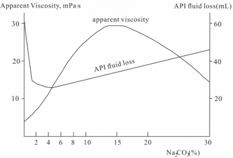
If the calcium ions are replaced with sodium ions, the clay particles will be more dispersible and form a thick diffused double layer, for the sodium ions have relatively low valence, a low ionic charge, and strong hydration ability. On the macroscale, the clay will exhibit higher apparent viscosity, faster mud-making rate, and lower water loss. Of course, if the content of sodium ions is too high, the adsorption layer on clay particles will attract too many cations, reducing the ζ potential of the particles and the thickness of the diffusion layer. Moreover, the extremely dense sodium ions are not sufficiently hydrated, and grab for the water molecules directly adsorbed by the clay particles. As a result, the hydration film of the clay particles becomes thinner, and the clay particles gradually turn from dispersed state to condensed state. On the macroscale, the apparent viscosity rises to the peak before a gradual decline, while the water loss plunges to the valley before a rebound (Figure 1). To optimize the mud-making effect, it is a must to optimize the alkali dosage. As shown in Figure 1, when the water loss is close to the requirement, the apparent viscosity is too low, resulting in a low mud-making rate; the peak mud-making rate can be obtained at the highest apparent viscosity, where the water loss is huge.
Figure 1. Changes of apparent viscosity and water loss during alkali treatment of calcium bentonite
2.3 Humic acid treatment agents
The following humid acid treatment agents are usually adopted to treat drilling fluid: coal alkali agent, nitro humic acid, sulfonated humic acid, chromium lignite, sulfamethyl lignite, and special resin mixture. The functions of these agents include dilution, viscosity reduction, water loss suppression, and inhibition of shale hydration.
Because the structure of humid acid is complex and variable, how the humid acid connects the layers of the clay has largely been interpreted empirically and speculatively. More data are needed to verify and correct the existing interpretations.
If the stratum is water sensitive, the mud performance can be adjusted to reduce water loss by adding a suitable amount of potassium humate.
2.4 High-efficiency lubricants
During exploratory drilling, high-efficiency lubricants can serve as the drilling fluid to increase the rotation speed of small-diameter diamond bit. The lubricants are adsorbed on the metal pipe and rock surface via the hydrophilic end of the active agent. In this way, the friction between the drill pipe and the rock becomes the friction between the liquid film or the hydrophobic ends of the surfactant. This is how high-efficiency lubricants play the role of lubrication and drag reduction.
Currently, high-efficiency lubricants can be prepared from the following active substances: (1) water-soluble anionic sodium soaps, e.g. sodium oleate soap, sodium rosinate soap, and sodium nitrates soap; (2) sulfonated asphalt products, e.g. sulfonated tar pitch; (3) esters and their admixtures, e.g. residue mixtures, and grease scrap; (4) complexes of some nonionic and anionic surfactants.
The dosage of high-efficiency lubricants is generally 0.1~1%. Anion lubricants, especially fatty acid sodium soaps, can be adsorbed firmly on metal rod, showing good lubricity. However, such lubricants may easily form insoluble substances in the face of divalent calcium and magnesium ions, which greatly reduce their lubricity. If the target stratum has a high content of calcium and magnesium ions, inorganic sodium salt needs to be added to remove these ions. Another treatment is to combine anionic and nonionic lubricants, improving the resistance to calcium and magnesium ions. In slow angle wireline core drilling, the diamond bit must be lubricated and cooled by a proper amount of lubricants to improve the drilling efficiency.
2.5 Plant gums
The good rheology of plant gums helps to stabilize the borehole, carry drilling debris, increase the drilling speed, and reduce the weak of drilling tools. Plant gums can effectively plug the leaking strata, such as broken stratum and sandstone layer. The speed of core drilling can be improved by applying plant gums to form a protective film over the rock.
3.1 Formula design
The indoor mud test results were optimized according to the properties of minerals in the target stratum. The mud system for the target stratum is composed of original mud + 5% clay + 2% soda. Then, three types of formulas were designed as follows:
3.1.1 Drilling fluids with low-solid phase mud
(1) Original mud + 1.5% cellulose + 2% potassium humate + 2% multi-effect plant gum SD-2 + 5% type 06 lubricant + water
(2) Original mud + 0.75% cellulose + 3% potassium humate + 3% multi-effect plant gum SD-2 + 5% type 06 lubricant + water
(3) Original mud + 0.75% cellulose + 5% potassium humate + 2% multi-effect plant gum SD-2 + 5% type 06 lubricant + water
3.1.2 Drilling fluids with no-solid phase mud
(4) 3% cellulose + 5% potassium humate + 4.5% high-efficiency water loss reducer + 6% multi-effect plant gum SD-2 + 5% type 06 lubricant + water
(5) 4.5% cellulose + 5% potassium humate + 4.5% efficient water loss reducer + 6% multi-effect plant gum SD-2 + 5% type 06 lubricant + water
3.1.3 Drilling fluids with weighted mud (using formula (3) of low-solid phase mud)
(6) Original mud + 0.75% cellulose + 5% potassium humate + 2% multi-effect plant gum SD-2 + 5% type 06 lubricant + 3% barite + water (γ=1.07)
(7) Original mud + 0.75% cellulose + 5% potassium humate + 2% multi-effect plant gum SD-2 + 5% type 06 lubricant + 5% barite + Water (γ=1.09)
(8) Original mud + 0.75% cellulose + 5% potassium humate + 2% multi-effect plant gum SD-2 + 5% type 06 lubricant + 10% barite + water (γ=1.12)
(9) Original mud + 0.75% cellulose + 5% potassium humate + 2% multi-effect plant gum SD-2 + 5% type 06 lubricant + 20% barite + water (γ=1.18~1.19)
3.2 Rheological tests of drilling fluids
The drilling fluids prepared with the above 9 kinds of muds were subjected to rheological tests. The test results are recorded in Table 5 below.
Table 5. The results of rheological tests of drilling fluids
|
Formula |
Mud Performance |
Apparent viscosity (mPa·s) |
Plastic viscosity (mPa·s) |
|||||||
|
Density (g/cm3) |
Water loss (mL) |
Φ600 (mPa·s) |
Φ300 (mPa·s) |
Φ200 (mPa·s) |
Φ100 (mPa·s) |
Φ6 (mPa·s) |
Φ3 (mPa·s) |
|||
|
Drilling fluids with low-solid phase mud |
||||||||||
|
(1) |
1.029 |
16.8 |
10.1 |
5.0 |
4.0 |
1.9 |
0.0 |
0.0 |
5.05 |
5.10 |
|
(2) |
1.032 |
10.6 |
10.0 |
4.0 |
3.2 |
1.0 |
0.0 |
0.0 |
5.00 |
6.00 |
|
(3) |
1.030 |
17.2 |
7.0 |
3.0 |
2.0 |
1.2 |
0.0 |
0.0 |
3.50 |
4.00 |
|
Drilling fluids with no-solid phase mud |
||||||||||
|
(4) |
1.020 |
24.4 |
18.0 |
10.0 |
6.0 |
2.9 |
0.0 |
0.0 |
9.00 |
8.00 |
|
(5) |
1.012 |
21.6 |
23.5 |
13.6 |
8.9 |
4.0 |
0.0 |
0.0 |
11.75 |
9.90 |
|
Drilling fluids with weighted mud (using formula (3) of low-solid phase mud) |
||||||||||
|
(6) |
1.043 |
6.8 |
10.5 |
4.8 |
2.4 |
2.0 |
0.0 |
0.00 |
5.25 |
5.70 |
|
(7) |
1.056 |
12 |
10.0 |
5.0 |
4.2 |
2.0 |
0.0 |
0.00 |
5.00 |
5.00 |
|
(8) |
1.115 |
8.4 |
11.0 |
6.0 |
5.2 |
3.1 |
0.0 |
0.00 |
5.50 |
5.00 |
|
(9) |
1.186 |
17.6 |
13.5 |
6.0 |
3.6 |
2.2 |
0.0 |
0.00 |
6.75 |
7.50 |
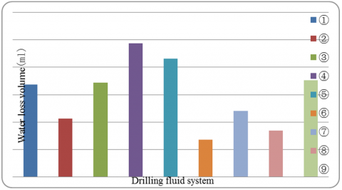
The above results show that the three drilling fluid systems can be ranked by water loss as drilling fluids with weighted mud < drilling fluids with low-solid phase mud < drilling fluids with no-solid phase mud. As shown in Figure 2, the water loss of the drilling fluid prepared by formula (2), a low-solid phase drilling fluid, could be obviously reduced by adding a proper amount of high-efficiency water loss reducer. When the dosage of that agent was similar, the water loss could be reduced by properly adding cellulose.
For low-solid phase mud, the viscosity could be enhanced by 85S cellulose and plant gum, while the water loss could be reduced by high-efficiency water loss reducer. This type of mud enjoys good rheology and shear dilution. Its apparent viscosity decreases sharply at high shear rate. The numerous functional groups on the polymer chain promotes the collapse resistance of the surface of water-sensitive strata and hard brittle strata.
For no-solid phase mud, the main components are cellulose, high-efficiency water loss reducer, plant gum, and type 06 lubricant. This type of mud is good at carrying cuttings to the well head. The mud also protects the borehole by creating a dense adsorption film on the borehole, and acts as an excellent lubricant and resistance reducer. Compared with clay-containing mud, no-solid phase mud has a low density, a flexible viscosity, and a good fluidity.
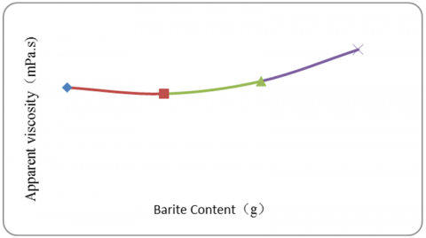
For weighted mud, with the growing dosage of barite, the weight of the mud increases, exerting an increasing pressure on the borehole. In the meantime, the apparent viscosity of the mud gradually rose.
However, the water loss of the mud increased with fluctuations, under the combined effects of the mud cake mass and pressure difference (as shown in Figures 3 and 4).
Figure 2. Comparison of water losses between drilling fluids
Figure 3. Water loss of weighted mud
Figure 4. Apparent viscosity of weighted mud
Figure 5. Relationship between water loss and apparent viscosity
As shown in Figure 5, the apparent viscosity of the mud does not always increase with the water loss. With the growth in apparent viscosity, the water loss of the mud is affected by the additives in the system. When the viscosity of the drilling fluid system reaches 5.5mPa·s, the water loss arrives at 4.2mL; the mud cake has a good quality. Further growth in viscosity will push up the water loss until the latter plunges under an excessively high apparent viscosity.
3.3 Expansion inhibition of drilling fluids
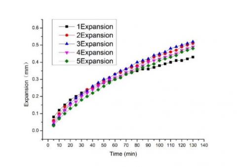
During recirculation, the drilling fluid is in full contact with the surrounding rock. The rock stratum generally contains lots of clay components (e.g. chlorite) that are easily soluble in water. The dissolution of these components leads to the hydration expansion and even deformation of the borehole. To prevent such accidents, a proper amount of expansion inhibitor should be added to the drilling fluid to reduce the hydration of mud and shale strata. The results of expansion inhibition tests on two drilling fluid systems are displayed in Table 6 and Figure 6.
As shown in Table 6 and Figure 6, with the elapse of time, the rock samples treated by each drilling fluid suffered expansion deformation, and the degree of deformation continued to increase. To some extent, the deformation could be inhibited by adding a proper amount of cellulose, when the viscosity and water loss were similar. The inhibition effect was obvious after 1h, as compared with the drilling fluids with no cellulose. In addition, the expansion deformation could also be significantly suppressed by adding 300mL cellulose into the drilling fluids with no-solid phase mud before 1h.
Figure 6. Comparison of expansion inhibition between drilling fluids
3.4 Lubrication performance of drilling fluid
Due to the slow angle of wireline core drilling, it is difficult to lower or retrieve the drilling tools. In the worst-case scenario, drilling tool retrieval may cause the borehole to collapse. This raises a strict requirement on the lubrication performance of drilling fluid, that is, the drilling fluid must have a small friction to reduce the exciting pressure in the borehole.
Figure 7. Comparison of friction coefficient between drilling fluids
As shown in Table 7 and Figure 7, the drilling fluids with no-solid phase mud clearly outperform those with low-solid phase mud. In the no-solid phase system, the drilling fluids show similar lubrication effect. In either drilling fluid system, the addition of cellulose could improve the friction resistance to a certain extent. To reduce the friction resistance, it is necessary to lower the dosage of cellulose and other viscosity lifting additives.
Table 6. Expansion inhibition of drilling fluids
|
Drilling fluid system |
Drilling fluids with low-solid phase mud |
Drilling fluids with no-solid phase mud |
|||
|
E (mm) T(min) |
(1) |
(2) |
(3) |
(4) |
(5) |
|
5 |
0.08 |
0.06 |
0.04 |
0.05 |
0.03 |
|
10 |
0.12 |
0.10 |
0.08 |
0.09 |
0.07 |
|
15 |
0.15 |
0.14 |
0.12 |
0.12 |
0.10 |
|
20 |
0.18 |
0.16 |
0.16 |
0.15 |
0.13 |
|
25 |
0.2 |
0.19 |
0.19 |
0.17 |
0.15 |
|
30 |
0.22 |
0.21 |
0.21 |
0.20 |
0.18 |
|
35 |
0.24 |
0.24 |
0.23 |
0.22 |
0.2 |
|
40 |
0.25 |
0.25 |
0.26 |
0.24 |
0.22 |
|
45 |
0.27 |
0.27 |
0.28 |
0.26 |
0.24 |
|
50 |
0.28 |
0.29 |
0.30 |
0.28 |
0.26 |
|
55 |
0.29 |
0.31 |
0.31 |
0.3 |
0.28 |
|
60 |
0.30 |
0.33 |
0.33 |
0.31 |
0.30 |
|
65 |
0.31 |
0.34 |
0.35 |
0.32 |
0.31 |
|
70 |
0.33 |
0.36 |
0.36 |
0.34 |
0.33 |
|
75 |
0.34 |
0.37 |
0.38 |
0.35 |
0.34 |
|
80 |
0.35 |
0.38 |
0.4 |
0.37 |
0.36 |
|
85 |
0.36 |
0.4 |
0.41 |
0.38 |
0.37 |
|
90 |
0.36 |
0.41 |
0.42 |
0.4 |
0.38 |
|
95 |
0.37 |
0.43 |
0.44 |
0.41 |
0.39 |
|
100 |
0.38 |
0.44 |
0.45 |
0.42 |
0.41 |
|
105 |
0.39 |
0.45 |
0.46 |
0.43 |
0.42 |
|
110 |
0.4 |
0.46 |
0.48 |
0.44 |
0.43 |
|
115 |
0.41 |
0.47 |
0.49 |
0.45 |
0.44 |
|
120 |
0.41 |
0.49 |
0.5 |
0.47 |
0.46 |
|
125 |
0.42 |
0.5 |
0.51 |
0.48 |
0.47 |
|
130 |
0.43 |
0.51 |
0.52 |
0.49 |
0.48 |
Table 7. Lubrication performance of drilling fluids
|
Drilling fluid system Friction coefficient |
Drilling fluids with low-solid phase mud |
Drilling fluids with no-solid phase mud |
|||
|
(1) |
(2) |
(3) |
(4) |
(5) |
|
|
0.65 |
0.63 |
0.61 |
0.45 |
0.41 |
|
During the field test, the drilling rig was installed after August 10, 2012, and the drilling started on August 13, 2012. During the drilling, casing wall protection was implemented twice, and 40 shifts were carried out effectively. The highest and average shift footages were 7.66m and 3.9m, respectively. The pure drilling time took up 52% of the entire operation. The average coring rate was 87%. The drilling completed at 157.61m on September 9, 2012. The target stratum mainly consists of ultrabasic rock mass, plus many wet deformation zones and mud layers. Since the stratum is broken and prone to collapse, the drilling fluid was prepared with low-solid phase mud, which guaranteed the successful drilling through the stratum. The situation of the field test is summed up in Tables 8 and 9.
Table 8. Summary of the field test for slow angle wireline core drilling
|
Borehole number |
DZK33-1 |
DZK31-1 |
DZK27-1 |
DZK25-1 |
DZK23-1 |
DZK21-1 |
|
Design depth |
113m |
266m |
110m |
140m |
120 |
110m |
|
Design inclination |
44° |
36° |
45° |
42° |
45° |
31° |
|
Target stratum |
The target stratum mainly consists of ultrabasic rock mass, plus many wet deformation zones and mud layers. Some drill holes pass through f16 fault. |
|||||
|
Open aperture |
75mm |
110mm |
75mm |
89mm |
89mm |
89mm |
|
Aperture type |
Level 1 |
Level 3 |
Level 1 |
Level 2 |
Level 2 |
Level 2 |
|
Final aperture |
75mm |
75mm |
75mm |
75mm |
75mm |
75mm |
|
Segmented drilling method |
Full-borehole wireline drilling |
First stage: 110mm single pipe drilling (0-7.9m); Second stage: 89mm ordinary two pipe drilling (7.9-14.26m); Third stage: 75mm wireline drilling (14.26m); Completion |
Full-hole wireline drilling |
First stage: 89mm ordinary two pipe drilling (0-6m); Second stage: 75mm wireline drilling (6m); Completion |
First stage: 89mm ordinary two pipe drilling (0-3.3m); Second stage: 75mm wireline drilling (3.3m); Completion |
First stage: 89mm ordinary two pipe drilling (0-5.04m); Second stage: 75mm wireline drilling (5.04m); Completion |
|
Drilling parameters |
Rig at gear 4-5; mud pump at gear 2 |
First stage: Rig at gear 2; mud pump at gear 3 Second stage: Rig at gear 3; mud pump at gear 2 Third stage: Rig at gear 4-5; mud pump at gear 2 |
Rig at gear 4-5; mud pump at gear 2 |
First stage: Rig at gear 3; mud pump at gear 2 Second stage: Rig at gear 4-5; mud pump at gear 2
|
First stage: Rig at gear 3; mud pump at gear 2 Second stage: Rig at gear 4-5; mud pump at gear 2
|
First stage: Rig at gear 3; mud pump at gear 2 Second stage: Rig at gear 4-5; mud pump at gear 2
|
|
Type of drilling fluid |
Low-solid phase mud |
Low-solid phase mud |
Low-solid phase mud |
Low-solid phase mud; no-solid phase mud |
Low-solid phase mud; no-solid phase mud |
Low-solid phase mud; no-solid phase mud |
|
Final depth |
114.2m |
233.26m |
119.95m |
131.49m |
140.46m |
96.33m |
Table 9. Summary of the field test for slow angle wireline core drilling (continued)
|
Borehole number |
ZK850-1 |
ZK850-2 |
|
Design depth |
90m |
120m |
|
Design inclination |
-2° |
-2° |
|
Target stratum |
The target stratum mainly consists of ultrabasic rock mass, plus many wet deformation zones and mud layers. |
|
|
Open aperture |
75mm |
89mm |
|
Final aperture |
75mm |
75mm |
|
Segmented drilling method |
First stage: 75mm wireline drilling (0-53.73m); 89mm single tube expansion; lowering protection tube; Second stage: 75mm wireline completion |
First stage: 89mm ordinary two pipe drilling (0-29.82m); lowering protection tube Second stage: 75mm wireline completion (29.82m) |
|
Drilling parameters |
Rig at gear 4-5; mud pump at gear 2 |
First stage: Rig at gear 3; mud pump at gear 2 Second stage: Rig at gear 4-5; mud pump at gear 2 |
|
Type of drilling fluid |
Low-solid phase mud; weighted mud |
Low solid-phase mud |
|
Final depth |
90.07mm |
157.61mm |
If the target stratum is relatively complete, the slow angle wireline core drilling should adopt the drilling fluid with no-solid phase mud: original mud + 4.5% cellulose + 5% potassium humate + 4.5% high-efficiency water loss reducer + 6% multi-effect plant gum SD-2 + 5% type 06 lubricant + water.
If the target stratum is broken and prone to collapse, the slow angle wireline core drilling should adopt the drilling fluid with low-solid phase bentonite mud: original mud + 0.75% cellulose + 2% potassium humate + 2% multi-effect plant gum SD-2 + 5% type 06 lubricant + water.
If the target stratum is the overburden or under high pressure, the slow angle wireline core drilling should adopt the drilling fluid with weighted mud: original mud + 0.75% cellulose + 5% potassium humate + 2% multi-effect plant gum SD-2 + 5% type 06 lubricant + 10% barite + water.
[1] Huo, J.H., Peng, Z.G., Ye, Z.B., Feng, Q., Zheng, Y., Zhang, J., Liu, X. (2018). Investigation of synthesized polymer on the rheological and filtration performance of water-based drilling fluid system. Journal of Petroleum Science and Engineering, 165: 655-663. https://doi.org/10.1016/j.petrol.2018.03.003
[2] Dejtaradon, P., Hamidi, H., Chuks, M.H., Wilkinson, D., Rafati, R. (2019). Impact of ZnO and CuO nanoparticles on the rheological and filtration properties of water-based drilling fluid. Colloids and Surfaces A: Physicochemical and Engineering Aspects, 570: 354-367. https://doi.org/10.1016/j.colsurfa.2019.03.050
[3] Okoro, E.E., Igwilo, K.C., Mamudu, A.O., Ekeinde, E.B., Dosunmu, A. (2018). Data on shale-water based drilling fluid interaction for drilling operation. Data in Brief, 19: 1620-1626. https://doi.org/10.1016/j.dib.2018.06.014
[4] Bán, A., Bálint, V., Nagy, S., Pach, F. (1983). The Feasibility of Increasing the Recovery Factor from the Nagylengyel Deposit in Hungary by Tertiary Oil Recovery using Ammonia Injection. In Improved Techniques for the Extraction of Primary Forms of Energy, pp. 157-158. https://doi.org/10.1007/978-94-009-6649-9_24
[5] Tannenbaum, E., Burgess, T., Kalessidis, V., Orban, A., Williams, J., Zanker, K. (1989). Measurement system and method for quantitatively determining the concentrations of a plurality of gases in drilling mud. U.S. Patent. 4,887,464. 19. https://doi.org/US4887464 A
[6] Bán, A., Bálint, V., Nagy, S., Pach, F. (1983). The feasibility of increasing the recovery factor from the Nagylengyel deposit in Hungary by tertiary oil recovery using ammonia injection. In Improved Techniques for the Extraction of Primary Forms of Energy, pp. 157-158. https://doi.org/10.1007/978-94-009-6649-9_24
[7] Volpon, A.G.T., De Melo, M.A., de Costo Casella, R., De Silva, I.P.G., Nicolau, H.C.C. (2009). Method and liquid for increasing the recovery factor in oil reservoirs. U.S. Patent Application No. 12/426,489. https://doi.org/US20090200015 A1
[8] Valenti, G.L., Sabatelli, V., Marchese, B. (1978). Hydration kinetics of tricalcium silicate solid solutions at early ages. Cement and Concrete Research, 8(1): 61-72. https://doi.org/10.1016/0008-8846(78)90058-3
[9] Habeeb, G.A., Mahmud, H.B. (2010). Study on properties of rice husk ash and its use as cement replacement material. Materials Research, 13(2): 185-190. https://doi.org/10.1590/S1516-14392010000200011
[10] Stalder, R., Ulmer, P., Thompson, A.B., Günther, D. (2000). Experimental approach to constrain second critical end points in fluid/silicate systems: Near-solidus fluids and melts in the system albite-H2O. American Mineralogist, 85(1): 68-77. https://doi.org/10.2138/am-2000-0108
[11] Mysen, B. (2013). Hydrogen isotope fractionation between coexisting hydrous melt and silicate-saturated aqueous fluid: An experimental study in situ at high pressure and temperature. American Mineralogist, 98(2-3): 376-386. https://doi.org/10.2138/am.2013.4247
[12] Valenti, G.L., Sabatelli, V., Marchese, B. (1978). Hydration kinetics of tricalcium silicate solid solutions at early ages. Cement and Concrete Research, 8(1): 61-72. https://doi.org/10.1016/0008-8846(78)90058-3
[13] Roy, D.K., Ray, G.K., Biswas, A.K. (2010). Overview of overpressure in Bengal basin, India. Journal of the Geological Society of India, 75(4): 644-660. https://doi.org/10.1007/s12594-010-0053-5
[14] Oliver, W.T., Mathews, S.A., Phillips, O., Jones, E. E., Odle, J., Harrell, R.J. (2002). Efficacy of partially hydrolyzed corn syrup solids as a replacement for lactose in manufactured liquid diets for neonatal pigs. Journal of Animal Science, 80(1): 143-153. https://doi.org/10.2527/2002.801143x
[15] Huang, J.B., Zhu, Y., Zhu, B.Y., Li, R.K., Fu, H.L. (2001). Spontaneous vesicle formation in aqueous mixtures of cationic surfactants and partially hydrolyzed polyacrylamide. Journal of Colloid and Interface Science, 236(2): 201-207. https://doi.org/10.1006/jcis.2000.7405
[16] Abdel-Azeim, S., Kanj, M.Y. (2018). Dynamics, aggregation, and interfacial properties of the partially hydrolyzed polyacrylamide polymer for enhanced oil recovery applications: insights from molecular dynamics simulations. Energy & Fuels, 32(3): 3335-3343. https://doi.org/10.1021/acs.energyfuels.8b00010
[17] Hale, A.H., Cowan, K.M. (1994). Drilling and cementing with blast furnace slag/silicate fluid. U.S. Patent No. 5,361,842. 8. https://doi.org/US5361842 A
[18] Wang, P.Q., LI, X.H. (2004). Experimental study of potassium silicate drilling fluid system. Journal-Southwest Petroleum Institute, 26: 20-24. https://doi.org/10.3863/j.issn.1000-2634.2004.03.006
[19] Ko, J.H., Tsukada, S., Kojima, S., Bokov, A.A., Ye, Z.G. (2010). Crossover in the mechanism of ferroelectric phase transition of Pb [(Mg1/3 Nb2/3)1− x Tix] O3 single crystals studied by Brillouin light scattering. Physical Review B, 82(10): 104110. https://doi.org/10.1103/PhysRevB.82.104110
[20] Duba, A., Constable, S. (1993). The electrical conductivity of lherzolite. Journal of Geophysical Research: Solid Earth, 98(B7): 11885-11899. https://doi.org/10.1029/93JB00995
[21] McKean, J.R., Johnson, D., Taylor, R.G. (2003). Measuring demand for flat water recreation using a two‐stage/disequilibrium travel cost model with adjustment for overdispersion and self‐selection. Water Resources Research, 39(4): 1107. https://doi.org/10.1029/2002WR001644
[22] Kumar, R., Kesavapillai, B. (2012). Stimulation of extracellular invertase production from spent yeast when sugarcane pressmud used as substrate through solid state fermentation. SpringerPlus, 1(1): 81. https://doi.org/10.1186/2193-1801-1-81