Mehmet Turgay Pamuk
© 2019 IIETA. This article is published by IIETA and is licensed under the CC BY 4.0 license (http://creativecommons.org/licenses/by/4.0/).
OPEN ACCESS
In this numerical work, the effects of baffles added in a Concentric Tube Heat Exchanger are studied, using a commercial software CFD (Computational Fluid Dynamics) package. The CFD model is made to grab all the physical phenomena such as heat transfer rating, temperature, velocity and pressure distributions within the computational domain. First the simplest model, the Heat Exchanger without baffles, is considered. Due to its limited capacity, baffles are added into the domain to investigate the heat transfer enhancement while observing pressure loss that is a direct indication of the pumping power for a given flow rate. A sufficiently high detailed geometry and fine mesh characteristics are adopted taking into account the computation resources and time, yet satisfactory enough to show that the numerical model can be validated using the analytical solutions relying on empirical heat transfer formulas. This gives researches working in Heat Exchanger area the opportunity to design their systems using CFD, without depending on a prototype that needs to be tested before the actual product is marketed. Normally, a new type of heat exchanger with a different tube diameter and baffle lay-out has to be manufactured using general a heat exchanger calculation approach that will most of the time require the revision of the preliminary design.
heat transfer, heat exchangers, concentric pipes, baffles, CFD
Heat Exchangers are essential equipment used in a wide area of applications ranging from HVAC to chemical processes, from power generation facilities to many sectors in industrial manufacturing. As the name suggests, it helps heat move from one medium to another. Radiator of a car helps most of heat generated by combustion and friction be carried to air incoming through the grills in front of a car. A pasteurizer in a dairy products manufacturing facility that heats up milk to a certain degree, then suddenly cools it down to kill bacteria, has also heat exchangers. However, not all these countless applications use the same type of heat exchangers. Depending on the required heat rate, cooled or heated media or physical limitations, they may be as simple as a concentric pipes type heat exchanger, or as complicated as a plate type heat exchanger with a very high area-to-volume ratio.
Among many types of heat exchangers, the concentric tube type is very common due to their very simple structure, lower cost and sturdiness. It consists of an outer tube that houses a concentric inner tube and two caps covering the ends of outer tube. Inside the inner tube is one fluid, mostly the cooling agent such as water and outside the inner tube is the fluid that needs to be cooled, such as oil, condensing steam etc. Within the scope of this study, first the simplest model, the Concentric Tube Heat Exchanger without baffles, is taken into account. The theory for this simplest model having no baffles in the flow paths is well established. Thus the numerical model can be easily validated. However, the need for enhancing the heat transfer achieved by this simplest model can be made possible by adding baffles that cause vigorous mixing of fluid leading an increase in heat transfer coefficient. On the other hand, it is shown that adding more baffles does not ever increase the heat transfer rates, implying the existence of an optimum baffles layout. Besides, the more the flow restrictions due to additional baffles, the more pressure loss that translates into the need for more pumping energy.
There are numerous studies on concentric heat exchangers in literature covering a wide range of diverse aspects. However, only the literature that cover Concentric Tube Heat Exchangers with a variety of flow restrictors and diverters are considered. No work in the literature has been found to be similar to the present study. Thus it is believed that the analytical and numerical work performed herein is unique. Omidi et al. [1] indicate in their paper that the active enhancement method is not widely used in double pipe heat exchangers which is believed that the authors should pay particular attention to this method. Verma et al. [2] investigated the effect of corrugations in heat transfer in concentric tube heat exchangers, using artificial neural networks. They found that the single helix tube increases the heat transfer co-efficient up to 1.5–2 times. The Nusselt number and heat transfer co-efficient is also increased in accordance with the increase in depth of the ribs, but some limitations apply. Celik et al. [3] studied the effect of corrugated inserts used in concentric heat exchangers. Applying Taguchi method and grey relational analysis, they ended up a design with the highest Nusselt number and lowest friction factor. Salem et al. [4] experimentally investigated the thermal performance of a double pipe heat exchanger with segmented perforated baffles. They found that installing segmental perforated baffles inside double pipe heat exchangers increases the heat transfer rate in addition to the pressure drop in the annulus side when compared with that in un-baffled heat exchangers. They also indicate that the Nusselt number and friction factor vary considerably depending on the factors such as the hole spacing, void ratio etc. Yadav and Sahu [5] investigated the heat transfer augmentation in double pipe air to water heat exchanger with helical disk turbulators. They reported that the Nusselt number was found to increase with the increase in Reynolds number and helix angle and was found to decrease with increase in diameter ratio. The friction factor increases with increase in helix angle and decreases with the increase in diameter ratio and Reynolds number. Hung et al. [6] implemented a CFD analysis for optimal design of a concentric heat exchanger with fins for high temperature systems. They concluded that staggered arrays of flat plates which support the concentric pipes can also serve as thermal fins which are shown to significantly enhance the heat transfer capability of the high temperature heat exchanger due to a large increase of heat transfer area and the occurrence of flow turbulence from impingement effect. The effectiveness of the high temperature heat exchanger can be raised by increasing the fin thickness. However, the benefit is offset when the thickness is greater than that of the baseline model.
On the other hand the fin length has the least impact on the effectiveness compared with other geometric parameters although it has the direct connection with the heat transfer area. Javaherdeh et al. [7] investigated the effects of fin height, optimal louver length and fin-louver contact thickness on the amount of heat transfer and pressure drop in a compact heat exchanger in their work. They validated their numerical results using several experimental tests were conducted in a wind tunnel facility, and found a good agreement between the experimental and numerical results. The variable parameters included the fin-tube contact thickness, louver length and fin height. They concluded that the ratio of optimal louver length to fin height is approximately 0.82.
As can be seen the selected literature, various authors have researched very distinct methods of heat transfer enhancement in Concentric Tube Heat Exchangers. Similarly, this study too, considers a different case that can be applied in heat exchanger field. As shown in the results sections of this study though, the applicability of the heat enhancement method explained herein has its own limits.
This paper consists of three chapters as well as a conclusion section. Following the introduction section above, the teoretical background in the field is summarized in the second section. Third section covers the analytical calculations based on the theory and the results of the CFD simulation. Finally, the conclusion section overviews the paper and brings up some comments regarding the results.
Before going into the details of the convective heat transfer, the basic parameters used are to be explained. Tables 1 and 2 provide a summary of the dimensional and non-dimensional parameters, respectively, used in the formulas is this section:
Table 1. Dimensional parameters
|
q”, Wm-2 |
h, Wm-2K-1 |
U, Wm-2K-1 |
Q'', W |
|
Heat Flux |
Convection coefficient |
Overall heat transfer coefficient |
Heat transfer rate |
Table 2. Non-dimensional parameters
|
e |
Nu |
Re |
Pr |
Pe |
|
Effectiveness |
Nusselt number |
Reynolds number |
Prandtl number |
Peclet number |
Convection, one of the three modes of heat transfer suggests that heat is transported from a higher temperature medium to a lower temperature one, one of the media being a fluid, as a linear function of temperature difference between these two media. The proportionality constant called “heat transfer coefficient” is dependent upon many factors such as flow velocity and thermo-physical properties of the fluid medium, and the surface conditions and physical orientation of the solid (Eq. 1).(1)
$\mathbf{q}^{\prime \prime}=\mathrm{h} \Delta \mathrm{T}$ (1)
Above equation gives the value for heat transfer rate per unit area, i.e. W/m2. However a heat transfer engineer mostly deals with the total heat transfer rate, i.e. $\dot{Q}=\boldsymbol{q}^{\prime \prime} A$. Unfortunately, $q^{\prime \prime}$ is not a simple figure to find out as it is a function of the length of the conduits most of the time, unless it is indicated as being constant. Therefore, for practical reasons, a more general approach is adopted (Eq. 2 ):
$\dot{\mathbf{Q}}=\mathbf{U A \Delta T}$ (2)
Here, U is an overall heat transfer coefficient to include all the media, materials, surfaces and thermal resistances (Eq. 3). R representing the thermal resistance such that $\dot{Q}=\Delta T / R$ [7]
$\mathrm{R}=\frac{1}{\mathrm{UA}}=\frac{1}{\mathrm{h}_{\mathrm{i}} A_{\mathrm{i}}}+\mathrm{R}_{\mathrm{t}}+\mathrm{R}_{\mathrm{f}}+\frac{1}{\mathrm{h}_{\mathrm{o}} \mathrm{A}_{\mathrm{o}}}$ (3)
where Rt is the thermal resistance of the tube material and Rf is the thermal resistance due to fouling. In the present analysis, they both have been neglected as the inner tube is copper, a high thermal conductivity material, and tubes are new. The most questionable part here in Eq. 2 is the temperature difference, $\Delta T$, as it varies along the heat exchanging surfaces, thus it is not a single value. However, differential analysis helps define a mean value for temperature difference $\Delta T_{m}$, or LMTD, logarithmic mean temperature difference [8] as
$\Delta \mathrm{T}_{\mathrm{m}}=\frac{\Delta \mathrm{T}_{1}-\Delta \mathrm{T}_{2}}{\ln \left[\frac{\Delta \mathrm{T}_{1}}{\Delta \mathrm{T}_{2}}\right]}$ (4)
where $\Delta T_{I}$ and $\Delta T_{2}$ are the temperature differences of flow media at two ends of the heat exchanger. However, logaritmic mean temperature cannot be calculated unless all the temperatures are known which is most of the time not the case.
There are two types of heat exchanger problems: the one where one is given the requirement for heating/cooling and a design for a brand new heat exchanger is initiated, and the other where one already has a heat exchanger at hand and needs to find out whether it serves a specific heat transfer need. Whichever the type of problem it is, one has to go through a detailed series of calculations, referring to various diagrams and come up with a result that may substantially deviate from the reality due to the nature of experimental heat transfer. Deviation in the surplus side means overdesigning, thus spending more money than necessary. On the other hand, underdesigning costs a lot more as it most of the time means sacrificing some of the equipment capacity, and maybe shutting down the equipment. Using a CFD model will not only help define the geometry better, but also all the characteristics of the heat exchanger to be designed can be visualized beforehand so that the time spent and resources allocated will be minimal. The current study fits in the second type of heat exchanger analysis which is called the effectiveness method [8]. The numerical model for the simple concentric heat exchanger (without baffles) is validated using this method given for this type of heat exchangers. In this method, a definition for the maximum heat transfer possible is made [8] as:
$\dot{\mathbf{Q}}_{\max }=C_{\min }\left(T_{h, i n^{-}} T_{c, i n}\right)$ (5)
where Cmin is the minimum of $\dot{\boldsymbol{m}}_{h} \mathcal{C}_{h}$ and $\dot{\boldsymbol{m}}_{c} c_{c}$. Additionally, another definition, number of thermal units, NTU=UAs/Cmin is made in order to calculate the effectiveness $\epsilon$ of a concentric pipe heat exchanger [8] such that $\dot{\boldsymbol{Q}}=\boldsymbol{\epsilon} \dot{\boldsymbol{Q}}_{\max }$:
$\epsilon=\frac{1-\exp [-\mathbf{N T U}(\mathbf{1}+\mathbf{c})]}{\mathbf{1}+\mathbf{c}}$; parallel flow (6a)
$\epsilon=\frac{1-\exp [-\mathrm{NTU}(1-\mathrm{c})]}{1-\mathrm{c} \exp [-\mathrm{NTU}(1-\mathrm{c})]} ;$ counter flow; counter flow (6b)
where c=Cmin/Cmax. As is simply the outer surface area of the inner tube. However, calculation of U, thus hi and horequires many steps of calculation. hi is relatively easy to calculate as it is related to the convective heat transfer for turbulent flow in circular pipes and a well known correlation is provided in almost all heat transfer text books:
Nu=0.023Re0.8 Prn (7)
where n=0.4 for heating and 0.3 for cooling and Nu=hDh/kf. Dh=4A/P, hydraulic diameter where P is the wetted perimeter and kfis the thermal conductivity of the fluid calculated at film temperature. However, heat transfer calculation for the flow domain between the two pipes is not this straight forward. Many correlations are available in the heat transfer literature for the convective heat transfer in annuli, space between two pipes. One of them is the work of Dirker and Meyer in which they provide a set of convective heat transfer correlations suitable for flows in annuli [9]. Another work on the subject is presented by Nonino et al. [10] also providing a Nusselt number correlation for an annulus which is used in this work.
$\overline{\mathbf{N u}_{\mathrm{c}}}=5.6443+\frac{0.070\left(\mathrm{X}^{*}\right)^{-1.35}}{1+0.119 \mathrm{Pr}^{-0.08}\left(\mathrm{X}^{*}\right)^{-\mathrm{n}}}$ (8)
where Pr belongs to the outer fluid, X*=x/(DhPe), non-dimensional channel length where Pe=RePr and n=0.801Pr0.0304-0.000155Pr.
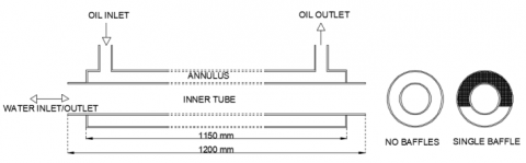
The current design consists of a copper inner tube with 25 mm inner diameter and an outer steel tube with 32 mm inner diameter. Both tubes have wall thicknesses of 1.5 mm. Although the inner tube is 1200 mm in length, the heat transfer section is 1150 mm which is housed by the outer tube (Figure 1). Baffled models have baffles covering almost 2/3 of the annulus area, extended from the center by a further 4 mm. Both water and oil connections are 25 mm. It is intended to cool a flow of oil at a flowrate of 30 lpm using water as coolant at a flowrate of 15 lpm. The inlet temperatures of oil and water are 330oK and 300oK, respectively. Oil has a kinematic viscosity of 20 cSt and density of 890 kg/m3. Outside surface of outer tube is assumed to be insulated.
Figure 1. Concentric tube heat exchanger
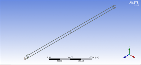
Using the above data and Eq.s 5-8, one comes up with U=1116 W/m2-C, NTU=0.1335, εparallel=0.1186, εcounter=0.1191 and $\dot{\mathbf{Q}}_{\max }$=25,365 W, thus $\dot{\mathbf{Q}}$parallel=3008 W and $\dot{\mathbf{Q}}$counter=3021 W. The numerical model is validated according to the these calculated values. Once the validation is achieved, then the results of baffled models are obtained and assumed to be reliable. The first step in using CFD is to construct the geometry (Figure 2) which belongs to the single baffle model shown as wireframe for better visualization. Owing to the symmetry of the geometry, only half of the domain is studied in order to facilitate the use of computational resources. The geometry of the heat exchanger used for model has 4 parts: Inner tube (with or without baffles), Outer tube, Flow domain (oil), Flow domain (water).
Figure 2. Model in ANSYS Fluent© (single baffle)
Figure 3. Mesh in ANSYS Fluent©
The second step is to construct the mesh for the fluid domain. Mesh size and type, thus the number of mesh elements decide both the precision of the results and the execution time. They were optimized by performing a series of trials until the calculations become invariant. A sample of mesh structure is shown in Figure 3, zoomed to put emphasis on details at ports.
Next step is the problem setup which is the most critical one. The pressure-based steady-state solver was chosen. Fluid flow with a designated inlet mass flow rate and temperatures considering realizable turbulent model coupled with energy equation is the model studied. ANSYS Fluent© is designed to simultaneously solve all three conservation equations, namely conservation of mass, momentum and energy, respectively, as follows, using finite volume formulation:
$\vec{\nabla} \cdot(\boldsymbol{\rho} \overrightarrow{\mathbf{V}})=\mathbf{0}$ (9)
$\vec{\nabla} \cdot(\boldsymbol{\rho} \overrightarrow{\mathbf{V}} \cdot \overrightarrow{\mathbf{V}})=-\vec{\nabla} \mathbf{p}+\vec{\nabla} \cdot(\overline{\overline{\tau}})+\boldsymbol{\rho} \overrightarrow{\mathbf{g}}$ (10)
$\vec{\nabla} \cdot([\overrightarrow{\mathbf{v}}(\boldsymbol{\rho} \mathbf{E}+\mathbf{p})])=\overrightarrow{\mathbf{\nabla}} \cdot\left[\mathbf{k}_{\mathrm{eff}} \overrightarrow{\mathbf{\nabla}} \mathbf{T}-(\overline{\overline{\tau}} . \overrightarrow{\mathbf{V}})\right]$ (11)
where $\overline{\overline{\tau}}$ represents the stress tensor and keff represents the effective thermal conductivity of fluids, both taking into account turbulent effects. Inlet boundary conditions are the aforementioned oil and water flow rates and temperatures. Outlet boundary condition is atmospheric air pressure, or zero gage pressure. Under-relaxation factors are adjusted in order to prevent divergence, even though this procedure slows down the convergence considerably.
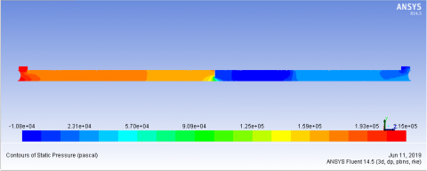
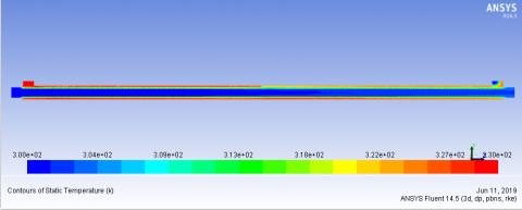
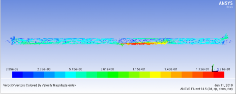
Figures 4-6 show the results of plain (baffleless) model to be validated. Heat transfer results show that the validated model has only a difference with analytical results by 2.8 % for parallel flow and 3.3 % for counter flow. The pressure drop computed by the model in oil side is DP=105 kPa for this case which is calculated as 109 kPa, representing a 3.8 % difference, using $\Delta P=\rho g h$ where h=f(L/Dh)V2/(2g) and f=64/Re as the flow is laminar (Re=531).
Figure 4. Pressure distribution, oil side (no baffles)
Figure 5. Temperature distribution (no baffles)
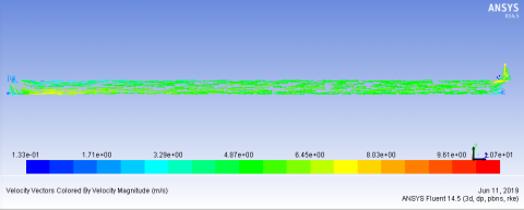
Figure 6. Velocity vectors (no baffles)
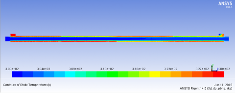
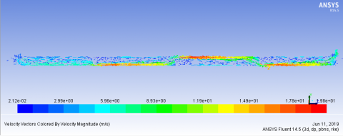
Figures 7-9 show the results of model with one baffle. Results show that, by adding one baffle in the oil flow path, the capacity of the heat exchanger is increased by 20.5 % for parallel flow and 23 % for counter flow. Vigorous mixing of fluid due to the single baffle has helped increase the rate of convection heat transfer, however at a penalty of 104.8 % increase in pressure drop.
Figure 7. Pressure distribution; oil side (single baffle)
Figure 8. Temperature distribution (single baffle)
Figure 9. Velocity vectors (single baffle)
Figures 10-12 show the results of model with three baffles. Results show that, by adding three baffles in the oil flow path, the capacity of the heat exchanger is increased by 14.5 % for parallel flow and 17.5 % for counter flow, however this time, at a penalty of 302 % increase in pressure drop.
Figure 10. Pressure distribution; oil side (three baffles)
Figure 11. Temperature distribution (three baffles)
Figure 12. Velocity vectors (three baffles)
It should be noted that the increasing the number of baffles do not increase the rate of convection heat transfer any further. Instead, a reduction in heat transfer rate is observed when compared to the single-baffle case. This is most probably because the furher mixing of fluid creates so much back flow behind the baffles that it prevents the heat from convected always in the flow direction. Table 3 gives a summary of the results for baffle configurations and flow direction as parallel (P) and counter flow (C):
Table 3. Summary of the results
|
No Baffles |
Single Baffle |
Triple Baffle |
||||
|
P |
C |
P |
C |
P |
C |
|
|
Q'', W |
3092 |
3121 |
3726 |
3839 |
3540 |
3667 |
|
DP, kPa |
109 |
223 |
438 |
|||
In this numerical work, the effects of baffles added in a Concentric Tube Heat Exchanger are studied, using the commercial software ANSYS Fluent©. The results have shown that, ANSYS Fluent© produces realistic outputs as far as the hydrodynamics and heat transfer in fluid flow through the concentric pipe heat exchangers are concerned. Studying the baffled models, it was shown that the heat transfer rate of a plain concentric tube heat exchanger can be considerably increased by adding a baffle in the flow path at the mid-length of the tubes, however at an elevated pressure drop, thus increasing the pumping costs. On the other hand, increasing the number of baffles does not necessarily guarantee an increase the heat transfer rate any further. It is concluded that the optimum number of baffles to obtain a higher heat transfer rate is dependent upon the length of the heat exchanger as well as the hydraulic diameter of annulus. This paper thus provides an invaluable information for the design of one of the most common types of heat exchangers, the concentric pipe type, by first validating the simplest type, i.e. the one without the baffles which is theoretically well established. Based on the reliability of this simplest model, more sophisticated geometries with baffles inside can readily be implemented with confidence.
c Specific heat, J.kg-1.K-1
d Diameter, m
Dh Hydraulic diameter, m
$\vec{g}$ Gravitational acceleration vector, ms-2
h Convection coefficient, Wm-2K-1
Nu Nusselt number, -
P Pressure, Pa or kPa
Pe Peclet number, -
Pr Prandtl number, -
R Thermal resistance, WK-1
Re Reynolds number, -
q” Heat Flux, Wm-2
$\dot{Q}$ Heat transfer rate, W
T Temperature, C or K
U Overall heat transfer coefficient, Wm-2K-1
$\vec{V}$ Velocity vector, ms-1
X* Non-dimensional tube length,-
Greek symbols
$\Delta$ Difference (P, T etc.)
$\epsilon$ Effectiveness,-
$\rho$ Density, kgm-3
$\mu$ Dynamic viscosity, Pas
$\overline{\overline{\tau}}$ Stress tensor, Pa
Subscripts
c cold side
h hot side
i inner side
in inlet
m mean value
o outer side
out outlet
[1] Omidi, M., Farhadi, M., Jafari, M. (2017). A comprehensive review on double pipe heat exchangers. Applied Thermal Engineering, 110: 1075–1090. http://dx.doi.org/10.1016/j.applthermaleng.2016.09.027
[2] Verma, T.N., Nashine, P., Singh, D.V., Singh, T.S., Panwar, D. (2017). ANN: Prediction of an experimental heat transfer analysis of concentric tube heat exchanger with corrugated inner tubes. Applied Thermal Engineering, 120: 219–227. http://dx.doi.org/10.1016/j.applthermaleng.2017.03.126
[3] Celik, N., Pusat, G., Turgut, E. (2018). Application of Taguchi method and grey relational analysis on a turbulated heat exchanger. International Journal of Thermal Sciences, 124: 85–97. http://dx.doi.org/10.1016/j.ijthermalsci.2017.10.007
[4] Salem, M.R., Althafeeri, M.K., Elshazly, K.M., Higazy, M.G., Abdrabbo, M.F. (2017). Experimental investigation on the thermal performance of a double pipe heat exchanger with segmental perforated baffles. International Journal of Thermal Sciences, 122: 39-52. http://dx.doi.org/10.1016/j.ijthermalsci.2017.08.008
[5] Yadav, S., Sahu, S.K. (2019). Heat transfer augmentation in double pipe water to air counter flow heat exchanger with helical surface disc turbulators. Chemical Engineering & Processing: Process Intensification, 135: 120–132. http://dx.doi.org/10.1016/j.cep.2018.11.018
[6] Hung, T.Z., Chen, H.C., Lee, D.S., Fu, H.H., Chen, Y.T., Yu, G.P. (2015). Optimal design of a concentric heat exchanger for high-temperature systems using CFD simulations. Applied Thermal Engineering, 75: 700-708, http://dx.doi.org/10.1016/j.applthermaleng.2014.09.079
[7] Javaherdeh, K., Vaisi, A., Moosavi, R. (2018). The effects of fin height, fin-tube contact thickness and louver length on the performance of a compact fin-and-tube heat exchanger. International Journal of Heat and Technology, 36(3): 825-834. https://doi.org/10.18280/ijht.360307
[8] Çenge, Y.A. (2003). Heat Transfer: A Practical Approach. 2nd Edition, ISBN-10: 9780072458930, McGraw Hill.
[9] Dirker, J., Meyer, J.P. (2005). Convective heat transfer coefficients in concentric annuli. Heat Transfer Engineering, 26(2): 38–44. http://dx.doi.org/10.1080/01457630590897097
[10] Nonino, C., Savino, S., Del Giudice, S. (2015). Annular ducts: Nusselt number correlations for laminar flows of liquids with temperature dependent properties. 11th International Conference on Heat Transfer, Fluid Mechanics and Thermodynamics, HEFAT 2015, Kruger National Park, South Africa. http://dx.doi.org/10.1088/1742-6596/547/1/012041