OPEN ACCESS
The present work aims to investigate a honeycomb system with PCM for solar energy applications. The solution is to combine the qualities of PCM and the honeycomb structure, in fact it spreads out the heat all over the PCM improving the effective thermal conductivity of the system. Transient regime numerical simulations are created for different pores per unit of length (PPU). The Solid-liquid PCM is paraffin wax. A numerical model with honeycomb structure is compared with a porous medium model. The porous medium is modelled with the extended Darcy-Brinkman law and to evaluate the heat exchange between the solid and the fluid zones a Local-Thermal Equilibrium assumption is used. By the results of the direct honeycomb model the characteristics such as permeability, inertial resistant coefficient, effective thermal conductivity and interfacial heat transfer are evaluated and then compared with the porous medium model. Numerical simulations were carried out using the Ansys-Fluent code. Results in terms of melting time, temperature fields, and stored energy as function of time are presented.
thermal storage, PCM, phase change material, porous media, honeycomb
Nowadays, one of the major problems in solar energy applications is the storage of the thermal energy. The energy demand has a continue variation while the thermal energy is depending on the wheather, therefore a buffer system that allows to charge or discharge itself in base of the evolution of demand is required in order to avoid the waste of the excess energy. A Thermal Energy system (TES) resolves these problems. In this study a Latent Heat Thermal Energy System (LHTESS) is employed to store the thermal energy. It based on the use of phase change materials (PCMs) to store thermal energy at quasi-constant temperature. In fact, during the phase change process, the heat is employed to change phase and not to increase the temperature [1]. The most common PCMs are the solid-liquid PCMs where the base material changes phase from solid to liquid and vice-versa. The melting temperature is different in base of the PCM nature. In literature [2, 3] are discussed some different type of PCM describing their thermophysical properties and the enhancement systems in thermal storage applications, because one of the most problem of the PCM is the low value of thermal conductivity. There are many type of improvement to increase the effective thermal performance of a thermal system using PCM, as the addition of metal foam [4], fins [5] or using an honeycomb structure. An honeycomb structure has the advantage to increase the heat exchange area between the PCM and an heat source. Moreover, it reduces the mechanical stress due to the PCM expansion during the phase change process [6]. The honeycomb structure is employed in various area of application, as thermal management area [7, 8] or building construction [9].
A honeycomb structure with phase change materials was studied in Pal and Joshi [8], after an experimental test a numerical number is set up. The honeycomb has a hexagonal cross-section and it was heated from bottom with a power input. The melting behavior of the PCM is modelled with the enthalpy porosity method. The results showed that the natural convection is negligible inside the honeycomb structure and there is a good agreement between the experimental data and numerical results. Li et al [10] prepared an inorganic PCM mixture of KNO3/NaNO3 inside a SiC ceramic honeycomb. They characterized the thermal properties of the PCM and by the results they found that the presence of the honeycomb delays the phase change process of the PCM respect to the unique PCM but the thermal energy storage rate is increased. Hasse et al. [11] both experimentally and numerically studied a honeycomb structure with PCM with a linear and sinusoidal cyclic temperature variation as thermal source. In conclusion, they affirm that the numerical results and experimental data present a good agreement. Luo et al [12] studied a ceramic honeycomb both experimentally and numerically. They compared the experimental data with a one-dimensional numerical model and by results they found that larger channels and thinner walls lead to a faster increase of exit temperature for the charging phase and higher decrease for the discharging phase.
A TES system with a honeycomb structure for solar application was studied in Andreozzi et al. [13]. The honeycomb was modeled as a porous media using the Local Thermal Non Equilibrium assumption (LTNE). A transient analysis about a honeycomb system with parallel squared channels was numerically studied in Andreozzi et al. [14]. Moreover, the honeycomb as treated as a porous media and by the results they found that for high number of channels the honeycomb system can be considered as a porous media.
In this paper a numerical model of an honeycomb system with PCM is employed. Transient regime numerical simulations are created for different pores per unit of length (PPU). The Solid-liquid PCM is Potassium carbonate (K2CO3). The numerical model with honeycomb structure is compared with a porous medium model. The porous medium is modelled with the extended Darcy-Brinkman law and to evaluate the heat exchange between the solid and the fluid zones a Local-Thermal-Equilibrium assumption is used. By the results of the real honeycomb model the characteristics such as permeability, inertial resistant coefficient, effective thermal conductivity and interfacial heat transfer are evaluated and then compare with the porous medium model. Results in terms of melting time and average temperature as function of time are presented.
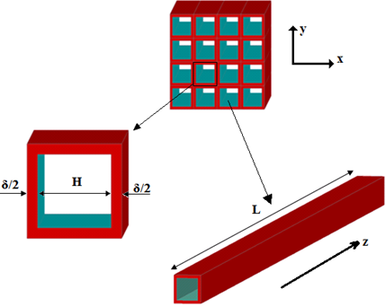
The system under consideration is an honeycomb structure with parallel squared channels, half of them are filled of PCM and in the others the heat transfer fluid (air) passes through in checkerboard way. The sketch of the honeycomb is depicted in figure 1.
The height of a single elementary channel (pore) is H and the thickness is δ and therefore the cross section area where the air flows is H x H. The length L of the honeycomb system is 1 m. The solid walls of the honeycomb are made of the ceramic cordierite. The PCM used in this simulation is Potassium carbonate (K2CO3). The PCM is enclosed inside the channels of the honeycomb and it is considered fixed without any movement, while the air passes through with a mass flux of 0.6 Kgm-2s-1. The thermal properties of the various material are listed in table 1.
Figure 1. Sketch of the honeycomb with the single channel size
Table 1. Thermal properties of the materials
|
Thermal properties |
Cordierite |
Air [15] |
K2CO3 [16] |
|
Density [kg/m3] |
2300 |
Ideal gas law |
2290 |
|
Specific Heat [J/kgK] |
900 |
Eq. 1 |
1513.69 [17] |
|
Thermal Conductivity [W/mK] |
2.5 |
Eq. 2 |
2 |
|
Dynamic Viscosity [kg/ms] |
- |
Sutherland law |
- |
|
Thermal expansion Coefficient [1/K] |
- |
- |
0.00011 |
|
Melting Heat [J/kg] |
- |
- |
235800 |
|
Melting Temperature [K] |
- |
- |
1170.15 |
The variation of thermal properties for the air is described by the following equations [15]:
${{c}_{p}}=1.06\cdot {{10}^{3}}-0.449T+1.14\cdot {{10}^{-3}}{{T}^{2}}-8\cdot {{10}^{-7}}{{T}^{3}}+1.93\cdot {{10}^{-10}}{{T}^{4}}$ (1)
$k=-3.93\cdot {{10}^{-3}}+1.02\cdot {{10}^{-4}}T-4.86\cdot {{10}^{-8}}{{T}^{2}}+1.52\cdot {{10}^{-11}}{{T}^{3}}$ (2)
The air passes through the honeycomb system while the PCM is confined inside it, in fact half of channels are closed where the PCM is blocked and the others are free to be passed through, as it showed in figure 2.
Figure 2. Sketch of inlet cross section for a unit of length
Therefore, the porosity in honeycomb configuration is:
${{\varepsilon }_{f}}=\frac{{{V}_{air}}}{{{V}_{total}}}=\frac{1}{2}\frac{{{H}^{2}}}{{{\left( H+2\delta \right)}^{2}}}$ (3)
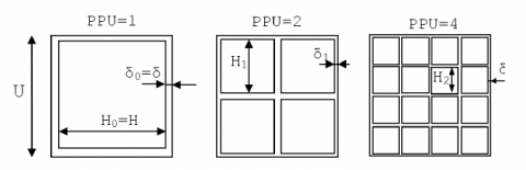
where Vair is the air volume and Vtotal is the packaging volume. The factor ½ is presented because half of channels are closed. Various honeycomb system for different pore per unit of length (PPU) are studied at the same porosity and volume. The honeycomb system with different PPU is reported in figure 3 in a unit length U. The relation between the channel height H and the thickness δ for different PPU is:
${{H}_{n}}=\frac{{{H}_{0}}}{{{2}^{n}}};\quad {{\delta }_{n}}=\frac{{{\delta }_{0}}}{{{2}^{n}}}$ (4)
where H0 and s0 are the values for 1 PPU and n = log2PPU.
Figure 3. Sketch of honeycomb system with 1, 2 and 4 pore per unit of length (PPU)
The direct simulation of the real honeycomb systems are then compared with a Local Thermal Equilibrium (LTE) porous model with the same characteristics.
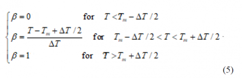
The enthalpy-porosity method is employed to simulate the melting and solidification of PCM [18]. In this method, a mixed solid-liquid phase region is present during the phase change. This region is described using a parameter called liquid fraction, β. Its value varies from 0 to 1 in the mushy region, while it is zero when the zone is fully solid and it is 1 when the zone is fully liquid:
where T is the local temperature, Tm is the melting temperature of the PCM. ΔT is the temperature range where the phase change occurs. In this study the ΔT is imposed to 2K. It is always more difficult to simulate the honeycomb system for higher PPU, because the geometric complexity and the computational costs are higher. Therefore, an equivalent porous model is used and it is compared with the real direct honeycomb system. In fact the honeycomb matrix can be considered as a porous medium where it is necessary to define the characteristics as effective thermal conductivity and permeability. The honeycomb porous model is anisotropic with an effective thermal conductivity that has a value along z direction different respect to x and y directions; the permeability K is considered only along the z direction, while along the x and y directions the permeability is null. The Darcy law is employed to describe the dynamic behavior of the flow in the porous media along the z direction. Given that the PCM is enclosed inside the walls of the honeycombs, it is considered as a part of the solid phase in the porous model. Moreover, Pal and Joshi [8] found that in a honeycomb structure the natural convection of the PCM can be neglected. The permeability K does not be affected by the PCM, because it depends only by the dynamic effects of the porous media.
K is calculated by the work of Bahrami et al. [19] where the average velocity uavg in a single channel with a square cross section is:
${{u}_{avg}}=\frac{\Delta p}{{{\mu }_{f}}L}{{\left( \frac{H}{2} \right)}^{2}}\left[ \frac{1}{3}-\frac{64}{{{\pi }^{5}}}\tanh \left( \frac{\pi }{2} \right) \right]$ (6)
Δp is the pressure drop along the channel, L is the channel length and μf is the dynamic viscosity of the fluid. A porous medium obey to the Darcy law for low values of Reynolds:
$\frac{\Delta p}{L}=\frac{\mu }{K}{{u}_{avg}}=\frac{\mu }{\varepsilon K}{{u}_{D}}$ (7)
Therefore, the permeability K for a single channel is:
$K=\varepsilon {{\left( \frac{H}{2} \right)}^{2}}\left[ \frac{1}{3}-\frac{64}{{{\pi }^{5}}}\tanh \left( \frac{\pi }{2} \right) \right]$ (8)
The permeability for different PPU is
$K=\varepsilon {{\left( \frac{{{H}_{n}}}{2} \right)}^{2}}\left[ \frac{1}{3}-\frac{64}{{{\pi }^{5}}}\tanh \left( \frac{\pi }{2} \right) \right]$ (9)
where uD is Darcy velocity, the relation between Darcy velocity and average velocity is uD=εuavg. The validity of the equation (11) is validated by Andreozzi et al. [14] up to Reynold number referred to channel height equals to 1000.
The real geometry model of the honeycomb is a conjugate heat transfer problem and it is compared with a porous model. in the porous model the Local Thermal Equilibrium assumption is considered to simulate the heat exchange between the air and the solid zone in the porous model. Obviously, the PCM is treated as a solid zone in the porous model.
The governing equations for 3D LTE porous model are the following:
$\frac{\partial u}{\partial x}+\frac{\partial v}{\partial y}+\frac{\partial w}{\partial z}=0$ (10)
$\begin{align}{{\rho }_{f}}\left( \frac{1}{{{\varepsilon }_{f}}}\frac{\partial u}{\partial t}+\frac{u}{\varepsilon _{f}^{2}}\frac{\partial u}{\partial x}+\frac{v}{\varepsilon _{f}^{2}}\frac{\partial u}{\partial y}+\frac{w}{\varepsilon _{f}^{2}}\frac{\partial u}{\partial z} \right)=-\frac{\partial p}{\partial x}+\frac{{{\mu }_{f}}}{{{\varepsilon }_{f}}}\left( \frac{{{\partial }^{2}}u}{\partial {{x}^{2}}}+\frac{{{\partial }^{2}}u}{\partial {{y}^{2}}}+\frac{{{\partial }^{2}}u}{\partial {{z}^{2}}} \right) \\\end{align}$ (11)
$\begin{align} {{\rho }_{f}}\left( \frac{1}{{{\varepsilon }_{f}}}\frac{\partial v}{\partial t}+\frac{u}{\varepsilon _{f}^{2}}\frac{\partial v}{\partial x}+\frac{v}{\varepsilon _{f}^{2}}\frac{\partial v}{\partial y}+\frac{w}{\varepsilon _{f}^{2}}\frac{\partial v}{\partial z} \right)= -\frac{\partial p}{\partial y}+\frac{{{\mu }_{f}}}{{{\varepsilon }_{f}}}\left( \frac{{{\partial }^{2}}v}{\partial {{x}^{2}}}+\frac{{{\partial }^{2}}v}{\partial {{y}^{2}}}+\frac{{{\partial }^{2}}v}{\partial {{z}^{2}}} \right) \\\end{align}$ (12)
$\begin{align} {{\rho }_{f}}\left( \frac{1}{{{\varepsilon }_{f}}}\frac{\partial w}{\partial t}+\frac{u}{\varepsilon _{f}^{2}}\frac{\partial w}{\partial x}+\frac{v}{\varepsilon _{f}^{2}}\frac{\partial w}{\partial y}+\frac{w}{\varepsilon _{f}^{2}}\frac{\partial w}{\partial z} \right)=-\frac{\partial p}{\partial z}+\frac{{{\mu }_{f}}}{{{\varepsilon }_{f}}}\left( \frac{{{\partial }^{2}}w}{\partial {{x}^{2}}}+\frac{{{\partial }^{2}}w}{\partial {{y}^{2}}}+\frac{{{\partial }^{2}}w}{\partial {{z}^{2}}} \right)-\frac{{{\mu }_{f}}}{K}w \\\end{align}$ (13)
Energy equation for the porous media in the case local thermal equilibrium (LTE), Ts=Tf=TPCM=Tcord=T is [20]:
$\begin{align} {{\left( \rho c \right)}_{eff}}\frac{\partial T}{\partial t}+{{\rho }_{f}}{{c}_{p,f}}\left( u\frac{\partial T}{\partial x}+v\frac{\partial T}{\partial y}+w\frac{\partial T}{\partial z} \right)=\frac{\partial }{\partial x}\left( {{k}_{x}}\frac{\partial T}{\partial x} \right)+\frac{\partial }{\partial y}\left( {{k}_{y}}\frac{\partial T}{\partial y} \right)\frac{\partial }{\partial z}\left( {{k}_{z}}\frac{\partial T}{\partial z} \right)-\varepsilon {{\rho }_{PCM}}{{H}_{L}}\frac{\partial \beta }{\partial t} \\\end{align}$ (14)
u,v,w are the air velocity and x,y,z are the Cartesian coordinates. ρf is the air density, p is the relative pressure, μf is the air dynamic viscosity, K is the permeability of the porous zone. Cp,f and kf are respectively the air specific heat and air thermal conductibility.
The effective heat transfer capacity is:
${{\left( \rho c \right)}_{eff}}=\varepsilon {{\left( \rho {{c}_{p}} \right)}_{f}}+\varepsilon {{\left( \rho {{c}_{p}} \right)}_{PCM}}+\left( 1-2\varepsilon \right){{\left( \rho {{c}_{p}} \right)}_{cord}}$ (15)
The component of the equivalent thermal conductivity of the solid phase is:
Parallel for heat conduction in the longitudinal direction (x-direction):
$\begin{align}{{k}_{z}}={{k}_{pcm}}\frac{{{A}_{pcm}}}{A}+{{k}_{f}}\frac{{{A}_{f}}}{A}+{{k}_{s}}\frac{{{A}_{s}}}{A}={{k}_{pcm}}\varepsilon +{{k}_{f}}\varepsilon +{{k}_{s}}\frac{{{A}_{s}}}{A}= \left( {{k}_{pcm}}+{{k}_{f}} \right)\varepsilon +{{k}_{s}}\left( 1-2\varepsilon \right) \\\end{align}$ (16)
The effective thermal conductivity along x and y directions can be calculate using the real honeycomb model, supposing the z direction adiabatic.
${{k}_{x}}={{k}_{y}}=0.753\ \frac{W}{mK}$ (17)
The effective thermal conductivities are used in LTE model, where there the thermal equilibrium is assumed. HL is the latent heat of fusion.
Two different model will be studied and then compared, the direct simulation of the honeycomb system for different PPU and the honeycomb system as a porous media at the same PPUs and porosity.
Ansys-Fluent 15.0 is selected as the computational software to solve the governing equations. A grid dependence test is accomplished in order to evaluate the best grid. The variation of temperature is monitored and the chosen mesh has 330000 cells, because in this case the relative error with the finest grid was 1.2%. A transient analysis is made with a time step size of 1.0 s. The SIMPLE algorithm is used for the pressure-velocity coupling, while PRESTO algorithm is used for the pressure calculation. Second order upwind scheme is used for energy and momentum equation. The inlet air temperature is 1473.15 K and the initial temperature of the system is 1073.15 K.
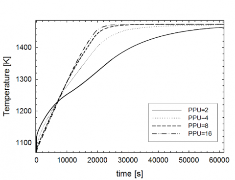
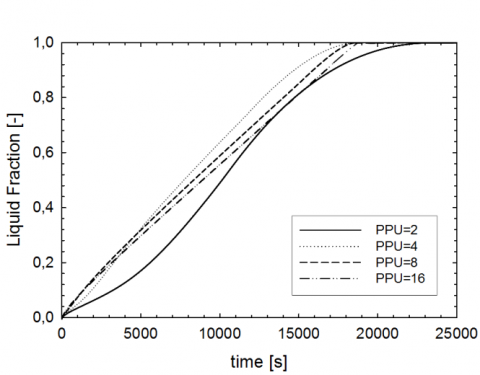
Figure 4 represents the average temperature evolution and the liquid fraction for different PPU. It is possible to see that for lower PPU the evolution of temperature is slower and for higher PPU is faster. This can be explained by the fact that for higher PPU the exchange area surface between air and the system is higher, moreover after PPU=8 the temperature evolution is the same.
(a)
b)
Figure 4. (a) Average evolution of the temperature of the system and (b) PCM liquid fraction during the time for different PPU
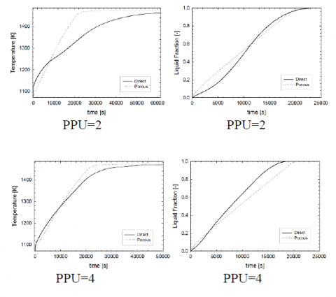
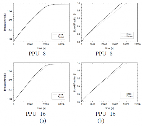
In figure 5, there is a comparison between the real honeycomb model and the porous model for different PPU relative to the temperature evolution and liquid fraction. For PPU=2 there are some differences between the two model but for PPU>2 these differences decreases up to the two models correspond each other for higher PPU.
Figure 5. (a) Average evolution of the temperature of the system and (b) PCM liquid fraction during the time for the direct and porous model
Therefore it is possible to use the LTE porous model to simulate the honeycomb structure only for higher PPU.
A numerical analysis of squared channel system honeycomb for the latent heat thermal energy is numerically studied. A comparison between a direct honeycomb system and an analogous LTE porous system is accomplished for different PPU. The differences are evident only for smaller PPU, because the heat transfer between system and air occurs through a smaller area exchange surface during the time, while for higher PPU this area is increased.
|
A |
Cross section Area, m2 |
|
c,cp |
Specific heat, J.kg-1.K-1 |
|
H |
Height of a single elementary channel, m |
|
HL |
Latent heat of fusion, J.kg-1 |
|
k |
Thermal conductivity W.m-1.K-1 |
|
K |
Porous Permeability, m2 |
|
L |
Length of a parallel channel, m |
|
n |
channel(Pore) Per Unit of length (PPU) |
|
p |
Static pressure, Pa |
|
t |
Time, s |
|
T |
Temperature, K |
|
u |
Air x-Velocity, m.s-1 |
|
U |
Unit of length, m |
|
v |
Air y-Velocity, m.s-1 |
|
V |
Volume, m3 |
|
W |
Width of the system, m |
|
w |
Air z-velocity, m.s-1 |
|
x |
Cartesian axis direction, m |
|
y |
Cartesian axis direction, m |
|
z |
Cartesian axis direction, m |
|
Greek symbols |
|
|
αsf |
Area Surface density, m |
|
β |
Liquid fraction |
|
μ |
viscosity |
|
δ |
Thickness of a single elementary channel, m |
|
ΔT |
Melting range temperature, K |
|
ρ |
Density, kg.m-3 |
|
Δp |
Air Pressure drop, Pa |
|
Subscripts |
|
|
air |
air |
|
avg |
average |
|
cord |
cordierite |
|
d |
dispersion |
|
D |
Darcy |
|
eff |
effective |
|
f |
Porous fluid phase, air |
|
m |
PCM melting |
|
PCM |
Phase change material |
|
total |
packaging |
|
n |
channel(Pore) Per Unit of length (PPU) |
|
s |
Solid phase of the porous zone |
[1] Zhou D., Zhao C.Y., Tian Y. (2012). Review on thermal energy storage with phase change materials (PCMs) in building applications, Appl. En., Vol. 92, pp. 593-605. DOI: 10.1016/j.apenergy.2011.08.025
[2] Sharma S.D., Sagara K. (2015). Latent heat storage materials and systems: A review, Int. J. Gr. En., Vol. 2, pp. 1-56. DOI: 10.1081/GE-200051299
[3] Zalba B., Marin J.M., Cabeza L.F., Mehling H. (2003). Review on thermal energy storage with phase change: Materials, heat transfer analysis and applications, Appl. Therm. Eng., Vol. 23, pp. 251-83. DOI: 10.1016/S1359-4311(02)00192-8
[4] Zhao C.Y., Lu W., Tian Y. (2010). Heat transfer enhancement for thermal energy storage using metal foams embedded within phase change materials (PCMs), Sol. En., Vol. 84, pp. 1402-1412. DOI: 10.1016/j.solener.2010.04.022
[5] Zhang Y., Faghri A. (1996). Heat transfer enhancement in latent heat thermal energy storage system by using the internally finned tube, J. Enh. H. Transf., Vol. 3, pp. 119-127. DOI: 10.1016/0017-9310(95)00402-5
[6] Farid M.M., Khudhair A.M., Razack S.A.K., Al-Hallaj S. (2004). A review on phase change energy storage: materials and applications, J. Energy Convers. Manage, Vol. 45, pp. 1597-1615. DOI: 10.1016/j.enconman.2003.09.015
[7] Kim T.Y., Hyun B.S., Lee J.J., Rhee J. (2013). Numerical study of the spacecraft thermal control hardware combining solid-liquid phase change material and a heat pipe, Aero. Sci. Tech., Vol. 27, pp. 10-16. DOI: 10.1016/j.ast.2012.05.007
[8] Pal D., Joshi Y.K. (1998). Thermal management of an avionics module using solid-liquid phase-change materials, J. Therm H. Transf., Vol. 12, No. 2, pp. 256-262. DOI: 10.2514/2.6329
[9] Lai C., Hokoi S. (2014). Thermal performance of an aluminum honeycomb wallboard incorporating microencapsulated PCM, En. Build, Vol. 73, pp. 37-47. DOI: 10.1016/j.enbuild.2014.01.017
[10] Li Y., Guo B., Huang G., Kubo S., Shu P. (2015). Characterization and thermal performance of nitrate mixture/SiC ceramic honeycomb composite phase change materials for thermal energy storage, Appl. Therm. Eng., Vol. 81, pp. 193-197. DOI: 10.1016/j.applthermaleng.2015.02.008
[11] Hasse C., Grenet M., Bontemps A., Dendievel R., Sallee H. (2011). Realization, test and modelling of honeycomb wallboards containing a phase change material, En. Build, Vol. 43, pp. 232-238. 2011. DOI: 10.1016/j.enbuild.2010.09.017
[12] Luo Z., Wang C., Xiao G., Ni M., Cen K. (2014). Simulation and experimental study on honeycomb-ceramic thermal energy storage for solar thermal systems, Appl. Therm. Eng., Vol. 73, pp. 620-626. DOI: 10.1016/j.applthermaleng.2014.07.053
[13] Andreozzi A., Buonomo B., Manca O., Tamburrino S. (2014). Thermal energy storages analysis for high temperature in air solar systems, Appl. Therm. Eng., Vol. 71, pp. 130-141. DOI: 10.1016/j.applthermaleng.2014.06.036
[14] Andreozzi A., Buonomo B., Manca O., Tamburrino S. (2015). Transient analysis of heat transfer in parallel squared channels for high temperature thermal storage, Comp. Therm. Sci., Vol. 7, pp. 477-489. DOI: 10.1615/ComputThermalScien.2016015327
[15] Wang F.Q., Shuai Y., Tan H.P., Yu C.L. (2013). Thermal performance analysis of porous media receiver with concentrated solar irradiation, Int. J. H. Transf., Vol. 62, pp. 247-254. DOI: 10.1016/j.ijheatmasstransfer.2013.03.003
[16] Zalba B., Marin J.M., Cabeza L.F., Mehling H. (2003). Review on thermal energy storage with phase change: Materials, heat transfer analysis and applications, Appl. Therm. Eng., Vol. 23, pp. 251-83. DOI: 10.1016/S1359-4311(02)00192-8
[17] Chase M.W., Jr. (1998). NIST-JANAF Themochemical Tables, Fourth Edition, The Journal of Physical Chemistry a Ref. Data, Monograph 9, pp. 1-1951.
[18] Al-abidi A., Bin Mat S., Sopian K., Sulaiman M.Y., Mohammed A.Th. (2013). CFD application for latent heat thermal energy storage: a review, Ren. Sust. En.ergy Rev., Vol. 20, pp. 353-363. DOI: 10.1016/j.rser.2012.11.079
[19] Bahrami M., Yovanovich M.M., Culham J.R. (2005). Pressure drop of fully-developed, laminar flow in microchannels of arbitrary cross-section, Proc. of ICMM, ed., 3rd International Conference on Microchannels and Minichannels, paper ICMM2005-75109. DOI: 10.1115/1.2234786
[20] Nield D.A. (2002). A note on the modeling of local thermal non-equilibrium in a structured porous medium, Int. J. H. Transf., Vol. 45, pp. 4367-4368. DOI: 10.1016/S0017-9310(02)00138-2