OPEN ACCESS
A theoretical study was carried out to determine the effect of collector length on the heat transfer and pressure drop characteristics of a wavy finned solar air heater. The flow channel was formed by two transversely positioned wavy fins attached below the absorber plate and the top surface is subjected to uniform heat flux. The effect of mass flow rate and collector length of wavy finned solar air heater was investigated. For the investigated range of parameters, the observations showed that increasing the collector length increases the total loss; useful energy gain and pressure drop but decreases the thermal efficiency. Also, an increase in air outlet temperature has been obtained with the lower mass flow rate and with the loss of minimum pressure drop, For the mass flow rate of 0.0138 kg/s the pressure drops for the wavy fin solar air heater increased from 4.01% to 23.4 % for the increase in collector length from 0.8 m to 6 m. Also, outlet temperature increases with the increase in collector length. Increasing the collector length will be ineffective beyond the mass flow rate of 0.05kg/s for the wavy fin solar air heater.
Collector Length, Thermal Efficiency, Pressure Drop, Solar Air Heater.
Solar collectors are widely used in different equipment for the utilization of solar thermal energy. Solar air heaters are cheap due to their simple design and are mostly used in solar energy collection devices [1]. The simple operation mechanism, low construction cost, and the utilization of both direct and diffuse solar radiation are the advantages of flat-plate collectors. Flat-plate solar air heaters utilize solar energy to heat air. The low heat transfer coefficient between the air and the absorber plate reduces the thermal efficiency of solar air heaters [2]. Another reason for the low thermal performance of solar air heaters is heat loss through the top glass cover, as the sides and the bottom of the collector are thermally insulated.
Many previous works [3-11] were carried out on the enhancement of thermal efficiencies in thermal systems where the air is used as a fluid of heat transfer. The analysis of the technical performances of seven solar air heaters of conventional design, one or two-pass and one or two cover glass, were studied by Biondi et al. [3]. Their study was generalized by means of two coefficients: air mass flow rate per unit collector area (G) and the collector geometric coefficient (K), which made collector performances invariant, under the same conditions of design, material choice and ambient values. Zero-capacitance model was used for the air heater performances and the graphs presented can be used when dealing with planning problems of air collectors. Also, analysis has been made by Choudhury and Garg [4] on corrugated and flat plate solar air heaters of one-pass on five different configurations with different air channel lengths and different specific mass flow rates of air. Their design analysis and the curves were intended to enable a designer to construct economical and efficient solar air heaters with technically logical air passage dimensions. Another study was carried out by Choudhury et al. [5] to determine the comparative performance of one-pass, corrugated, air heaters with different widths of the air channel and for different specific mass flow rates of air. They also evaluated the sensitivity of optimization to changes in collector parameters and operating conditions. Joudi and Mohammad [6] performed the experiments to evaluate the performance of a ‘‘V’’ corrugated-plate solar air heater during clear day in winter and summer. An air outlet temperature of 70°C was obtained in summer at midday with an average collector efficiency of 42%. Ghodbane et al. [15] studied the solar flat collector with air as fluid. They calculated the solar radiation in various sites of Algeria and the influence of various parameters. Their results showed that these types of air heaters are useful in winter and also for drying.
Adding fins in the airflow pass is widely regarded as an effective way to enhance thermal efficiency and a large number of comparative studies with different fin structures have been conducted under various working conditions. For example, Tanda [7] experimentally assessed the relative merit of several rib configurations under different Reynolds number values by investigating the heat transfer coefficients and friction factors of the heaters. Karim and Hawlader [8] found that the v-corrugated heater works at a higher thermal efficiency than the conventional flat heater and recommended a specific airflow rate for drying purposes based on the thermal efficiency and outlet air temperature. Yildiz et al. [9] designed a solar air heater by incorporating aluminum wool on a perforated plate in the airflow pass, and then evaluated its thermal performance with the conventional heater in respect to the outlet air temperature rise under the same working scenario. Studies pointed out that adding compact fins on the absorber plate can strengthen the convective heat transfer in the airflow pass without leading to a large pressure drop. Youcef-Ali [10] stated that the offset strip fin could guarantee high convective heat transfer area per unit airflow volume and low-pressure losses of the heater. Then they developed a heat transfer model for heater design [11]. First law and second law analysis of a water-cooled PV/T module has been discussed to study the drawback for optimal exploitation of the technology to maximize the total energy harvested by the system [17]. Experimental investigation and performance comparison of cross flow solar air heater with inline hole jet plate and staggered hole jet plate have been done by Vinod and Shailendra [18] to find the outlet air temperature, collector efficiency and heat transfer. They found better performance with inline hole jet plate than those of staggered hole plate solar air heater.
From the literature review mentioned above, it should be understood that wavy fins can be used for analysis of fluid flow characteristics in solar air heater. No systematic investigations on the system and operating parameters on the heat transfer and pressure drop performance have been carried out that may be useful for the optimal design of such systems.
With an exception of a recent paper by Priyam et al. [12-14] who studied fully developed convection problem in wavy fin solar air heater, there is no investigation studying this solar air heater on the length of collector. This has motivated the present theoretical study for fully developed turbulent flow under constant wall heat flux for a solar air heater with wavy fin. The C++ programming language with gauss-seidal iterative numerical method was used to solve the problem.
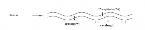
Consider a solar air heater having an absorber plate of length 'L' and width 'W', provided with 'n' number of fins of uniform thickness 'df' and height 'hf' are spaced at a mean distance of 'w' as shown in fig.1. The geometric descriptions of a fin have been shown in fig.2. The distance between the absorber plate and bottom plate is 'H'. The solar air heater used is a single pass between the absorber plate and bottom plate. The steady state efficiency of solar air heater is given by the following equations, known as Hottel-Whiller-Bliss equation [1]
$\eta_{t h}=\frac{Q_{u}}{A_{c} \mathrm{xI}}$ (1)
The expression for useful energy gain [1] in terms of collector heat removal factor, collector overall loss coefficient based on the absorber plate and the ambient temperature is expressed as:
$Q_{u}=F_{R} A_{c}\left(S-U_{L}\left(T_{f i}-T_{a}\right)\right)$ (2)
An empirical relation has been used for calculation of top loss coefficient (Ut) is given by Klein, bottom loss coefficient (Ub) and side loss coefficient (Us) and the total loss coefficient (UL) is given as [2]:
$\mathrm{U}_{\mathrm{L}}=\mathrm{U}_{\mathrm{t}}+\mathrm{U}_{\mathrm{b}}+\mathrm{U}_{\mathrm{s}}$ (3)
where
$\mathrm{U}_{\mathrm{s}}=\frac{(\mathrm{L}+\mathrm{W}) \mathrm{Hk}_{\mathrm{i}}}{\mathrm{L} \mathrm{W} \delta_{\mathrm{s}}}$ (4)
$\mathrm{U}_{\mathrm{b}}=\frac{\mathrm{k}_{\mathrm{i}}}{\delta_{\mathrm{b}}}$ (5)
$U_{t}=\left[\frac{N_{g c}}{\left(\frac{C}{T_{p m}}\right)\left(\frac{T_{p m}-T_{a}}{N_{g c}+f^{\prime}}\right)^{0.33}}+\frac{1}{h_{w}}\right]^{-1}+$$\left[\frac{\sigma\left(T_{p m}^{2}+T_{a}^{2}\right)\left(T_{p m}+T_{a}\right)}{\frac{1}{\varepsilon_{p}+0.05 N_{g c}\left(1-\varepsilon_{p}\right)}+\frac{2 N_{g c}+f^{\prime}+1}{\varepsilon_{c}}-N_{g c}}\right]$ (6)
where
The collector efficiency factor is expressed as:
$f^{\prime}=\left(1+0.04 h_{w}+0.0005 h_{w}^{2}\right)\left(1+0.091 N_{g c}\right)$
$C=365.9\left(1-0.00883 \theta+0.0001298 \theta^{2}\right)$
$h_{w}=5.7+3.8 V_{w}$ (7)
where, he is the equivalent heat transfer coefficient and can be derived from energy balance equations.
Let b is the area enhancement factor which is defined as the heat transfer surface area of wavy fins to that of a plane (flat) rectangular fins of the same height and length [2]. Energy balances for absorber plate, bottom plate and air stream [1] are shown in equations (8-10).
For absorber plate;
$S-U_{t}\left(T_{p m}-T_{a}\right)-h_{f p}\left(T_{p m}-T_{f}\right)-h_{r}\left(T_{p m} T_{b m}\right)-(2 / w) h_{f} \phi_{f} \beta h_{f f}\left(T_{p m}-T_{f}\right)=0$ (8)
For bottom plate;
$h_{r}\left(T_{p n}-T_{b m}\right)-h_{f 0} T_{b m}-T_{f} )-U_{b}\left(T_{b m}-T_{a}\right)=0$ (9)
For air stream;
$Q_{u}-h_{f p}\left(T_{p m}-T_{f}\right)-h_{f b}\left(T_{b m}-T_{f}\right)-(2 / w) h_{f} \phi_{f} \beta h_{f f}\left(T_{p m}-T_{f}\right)=0$ (10)
where $\emptyset_{f}$ is the fin efficiency and can be expressed as
$\phi_{f}=\frac{\tanh m h_{f}}{m h_{f}}$ (11)
where, $\mathrm{m}=\left[\frac{2 h_{f f}}{k_{a} \delta_{f}}\right]^{1 / 2}$
Solving the above equations for the expression, the expression for he is given as:
$\mathrm{h}_{\mathrm{e}}=\mathrm{h}_{\mathrm{fp}}\left(1+\frac{2 \mathrm{h}_{\mathrm{fb}} \mathrm{h}_{\mathrm{ff}}}{\mathrm{wh}_{\mathrm{fp}}}\right)+\frac{\mathrm{h}_{\mathrm{r}} \mathrm{h}_{\mathrm{fb}}}{\mathrm{h}_{\mathrm{r}}+\mathrm{h}_{\mathrm{fb}}}$ (12)
The heat transfer coefficients between air and three sides of duct walls may be assumed to be equal i.e.
$h_{f f}=h_{f p}=h_{f b}=\frac{N u \cdot k_{a}}{D_{h}}$ (13)
Figure 1. Solar air heater without fin and with wavy fin
Figure 2. Geometric description and flow representation of a wavy fin
For air the following correlation may be used for laminar flow in a rectangular duct [1],
$N u=4.4+\frac{0.00398\left(0.7 \mathrm{Re}^{D_{h} / L}\right)^{1.66}}{1+0.00114\left(0.7 \mathrm{Re}^{D_{h} / L}\right)^{1.12}}$ (14)
For turbulent flow the correlation may be derived from Kay's data with the modification of Mc Adams for a rectangular channel as follows [1].
$N u=0.0158 \mathrm{Re}^{0.8}\left[1+\left(D_{h} / L\right)^{0.7}\right]$ (15)
and for calculating the Nusselt number, the correlation of the colburn factor (j) is recommended by Dong et al. [16] and used for wavy fin.
$j=0.0836 \mathrm{Re}^{-0.2309}$$\left(\frac{w}{h_{f}}\right)^{01284}\left(\frac{w}{2 . a m p}\right)^{-0.153}\left(\frac{L}{\lambda}\right)^{-0.326}$ (16)
where j=Nu/Re.Pr1/3
The hydraulic diameter, Dh for plane and wavy finned solar air heater is;
For plane solar air heater
Dh= 4(H x W)/2(H + W) (17)
For wavy fin solar air heater
Dh=4pAfrL/Ar (18)
where Ar, cross sectional area for wavy fin solar air heater and given by;
$A_{r}=\left(n \mathrm{x} L^{\prime} \mathrm{x} \delta_{f}\right)+\left(2 n \mathrm{x} L^{\prime} \mathrm{x} h_{f}\right)+((n+1) \mathrm{x} L \mathrm{x} w)$ (19)
Gauss-siedel iterative procedure is used to calculate the mean plate temperature [2].
$T_{p c a l}=T_{a}+\frac{Q_{u}\left(1-F_{R}\right)}{A_{P} U_{L} F_{R}}$ (20)
First an assumption of mean plate temperature is made from which UL is calculated, with approximate values of FR, F' and Qu, a new value of mean plate temperature is obtained from equation (20) and used to calculate a new value of top loss coefficient and this is repeated until the accuracy of 0.01% is achieved.
The outlet temperature of the collector can be obtained as;
$\frac{T_{f o}-T_{a}-S / U_{L}}{T_{f i}-T_{a}-S / U_{L}}=\exp \left[\frac{-A_{C} U_{L} F^{\prime}}{\dot{m} C_{P}}\right]$ (21)
The friction factor along the collector is:
f=0.079Re-0.25 (Plane solar air heater) (22)
and for wavy fin Dong et al. [16] developed the correlation for f- factor
$f=1.16 \mathrm{Re}^{-0.309}$$\left(\frac{w}{h_{f}}\right)^{0.3703}\left(\frac{w}{2 a m p}\right)^{-0.25}\left(\frac{L}{\lambda}\right)^{-0.1152}$ (23)
The pressure drop along the collector can be calculated for both solar air heaters from the relation [1].
$\Delta P=\frac{4 f L \rho v^{2}}{2 D_{h}}$ (24)
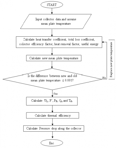
The flowchart representing the solution procedure to determine the heat transfer and pressure drop of wavy fin solar air heater is shown in figure 3.
Based on the theoretical analysis, the following curves have been plotted for the heat transfer and pressure drop characteristics of wavy fin solar air heater. The various input parameters taken for the analysis have been listed in Table.1.
Figure 3. Flowchart for calculating heat transfer and pressure drop for a wavy fin solar air heater
Fig.4 shows the total loss coefficient as a function of collector length and mass flow rate. It shows that for the entire range of mass flow rate, total loss coefficient increases as the increase in collector length. For the same mass flow rate of 0.0138 kg/s, wavy fin solar air heater showed lower loss coefficient than the plane solar air heater up to a collector length of 1.4 m, beyond this length of collector, the wavy fin solar air heater showed the maximum total loss coefficient. This may because increasing the collector length increases the mean plate temperature but for the fixed collector length, increasing the mass flow rate decreases the mean plate temperature and hence the total loss coefficient decreases. Fig. 5 shows the plot for useful energy gain as a function of collector length and mass flow rate. Increasing the mass flow rate, useful energy gain increases. For a constant mass flow rate, wavy fin solar air heater shows more useful energy gain. As the collector length increases, the useful energy gain increases. This is due to increase in collector length leads to increase in the effective heat transfer area. Fig. 6 shows the thermal efficiency as a function of mass flow rate and collector length. Thermal efficiency increases with the increase in collector length. For a constant mass flow rate of 0.0138 kg/s, the thermal efficiency decreases up to 58% when the collector length increases from 0.8 m to 6 m for the wavy fin solar air heater. Whereas, for the plane solar air heater the decrement is up to 37%. The decrement in efficiency occurs due to higher losses occurred with the increase in collector length. The outlet temperature as a function of collector length and mass flow rate can be seen in fig.7. It shows that at lower mass flow rate, increasing the length of the collector from 0.8 m to 6 m, the outlet temperature increased from 335 K to 398.7 K, but, for the mass flow rate beyond 0.05 kg/s and collector length 3.2 m the air temperature decreases, although the collector length increases. This may because higher collector length leads to lower absorber plate temperature at higher mass flow rate and thus the higher heat losses. It can be seen from fig.8 that the pressure drop along the collector increases as the collector length increases. Lower collector length at lower mass flow rate leads to less pressure drop, but as the collector length increases the heat loss to the surrounding increases and thus pressure drop increases. Table 2 shows the effect of increasing collector length on various performance parameters.
Figure 4. Total loss coefficient as a function of collector length and mass flow rate
Figure 5. Useful energy gain as a function of collector length and mass flow rate
Figure 6. Thermal efficiency as a function of collector length and mass flow rate
Figure 7. Air outlet temperature as a function of collector length and mass flow rate
Table 1. Input and boundary parameters
|
Parameters |
Value |
Parameters |
Value |
|
I |
900 W/m2 |
w |
1 cm |
|
W |
1 m |
Ta |
30°C |
|
H |
2.5 cm |
Tfi |
30°C |
|
hf |
2cm |
Vw |
2.5 m/s |
|
((ta)e) |
0.85 |
L |
0.8 m-6 m |
|
dins |
5cm |
ṁ |
0.0138 kg/s -0.11 kg/s |
|
amp |
7.5 mm |
l |
70 mm |
Figure 8. Pressure drop along the collector as a function of collector length and mass flow rate
Table 2. Effect of collector length on various performance parameters
|
Parameter |
Mass flow rate (kg/s) |
Effect by using wavy fin solar air heater than the plane solar air heater at L=0.8 m |
Effect by using wavy fin solar air heater than the plane solar air heater at L=6 m |
|
Total loss coefficient |
0.0138 |
Decreased by 3.07% |
Increased by 7.73% |
|
Thermal efficiency |
0.0138 |
Increased by 173.1% |
Increased by 102.4% |
|
Useful heat gain |
0.0138 |
Increased by 181.8% |
Increased by 101.4% |
|
Outlet temperature |
0.0138 |
Increased by 6.4% |
Increased by 13.62% |
|
Temperature rise |
0.0138 |
Increased by 173.9% |
Increased by 99.34% |
|
Pressure drop along collector |
0.0138 |
Increased by 4.03 times |
Increased by 25.54 times |
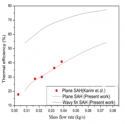
In order to verify the accuracy and reliability of the present results, a comparison is made with the results available in the literature. Due to unavailability of the experimental study on wavy fin solar air heater a comparison is made with the experimental study for the simplest geometry with plane solar air heater. Fig. 9 shows the variation of thermal efficiency for the plane and wavy finned solar air heater. Although an underestimation is observed but the agreement between the present result and that of Karim et al. [8] for plane solar air heater is good.
Figure 9. Comparison of plane and wavy fin solar air heater with the available results in literature
A deviation of ±4.72% has been found as compared to the analyzed plane solar air heater of Karim et al [8]. The variation is because in the case of forced convection, the physical properties of air as a function of temperature play the main role. Also, the climatic conditions of experimental study influence the performance. Therefore, this underestimation can be imputed to the difference between the function which are used by Karim et al. [8] to evaluate physical properties of air and operating conditions, which are employed in this study.
Fully developed heat transfer and pressure drop characteristics of the solar air heaters with wavy fin were obtained by using C++ programing language and the effect of collector length has been obtained. The main conclusions of the results are given below:
(a) The pressure drop along the collector increases as the collector length increases for the all mass flow rates. At the lower mass flow rate of 0.0138kg/s the pressure drop for the wavy fin solar air heater is 4.01% for the collector length of 0.8 m whereas it increases to 23.4 % for the collector length of 6 m.
(b) Outlet temperature increases with the increase in collector length. Also, increasing the collector length became ineffective beyond the mass flow rate of 0.05kg/s for the wavy fin solar air heater.
(c) The thermal efficiency decreases as the collector length increases from 0.8 m to 6m. Lesser steeper fall has been noted for the higher collector length, i.e. beyond 1.4 m.
|
Ac |
Collector area (m2) |
||
|
Afr |
Minimum free flow area (m2) |
||
|
amp Ap |
Amplitude of wavy fin (mm) Area of absorber plate (m2) |
||
|
Ar |
Total heat transfer area (m2) |
||
|
C |
Constant (defined by equation 6) |
||
|
Cp |
Specific heat at constant pressure (J/kgK) |
||
|
Dh |
Hydraulic diameter (m) |
||
|
f' |
Constant used to evaluate top loss coefficient |
||
|
H |
Spacing between absorber plate and bottom plate (m) |
||
|
he |
Effective heat transfer coefficient (W/m2K) |
||
|
hf |
Height of fin (m) |
||
|
hff |
Convective heat transfer coefficient between air to air(W/m2K) |
||
|
hfp |
Convective heat transfer coefficient between air and absorber plate(W/m2K) |
||
|
hr |
Radiative heat transfer coefficient(W/m2K) |
||
|
Hw |
Wind heat transfer coefficient (W/m2K) |
||
|
I |
Intensity of Solar radiation (W/m2) |
||
|
ka |
Thermal conductivity of air (W/mK) |
||
|
kGI |
Thermal conductivity of G.I sheet (W/mK) |
||
|
ki |
Thermal conductivity of insulating material (W/mK) |
||
|
L |
Length of the collector/ Absorber plate (m) |
||
|
L' |
Actual length of wavy fin (m) |
||
|
n |
Number of fins |
||
|
Ngc |
Number of glass covers |
||
|
p |
Porosity |
||
|
Qu |
Useful thermal energy gain (W/m2) |
||
|
S |
Absorbed Solar Energy, I(ta)e (W/m2) |
||
|
Ta |
Ambient Temperature (°C) |
||
|
Tfi |
Inlet air temperature (°C) |
||
|
Tfo |
Outlet air temperature (°C) |
||
|
Tpcal |
Calculated Mean plate temperature (K) |
||
|
Tpm |
Mean plate temperature (K) |
||
|
Tsky |
Sky temperature (K) |
||
|
Ub |
Bottom loss coefficient (W/m2K) |
||
|
UL |
Total loss coefficient (W/m2K) |
||
|
Ut |
Top loss coefficient (W/m2K) |
||
|
v |
Average air velocity (m/s) |
||
|
Vw |
Wind velocity (m/s) |
||
|
w |
Wavy fin spacing (cm) |
||
|
W |
Width of the collector/ Absorber plate (m) |
||
|
df |
Thickness of fin (m) |
||
|
Dimensionless numbers |
|||
|
Re |
Reynolds number |
||
|
Pr |
Prandtl number |
||
|
Nu |
Nusselt number |
||
|
j |
Colburn j -factor |
||
|
f |
Friction factor |
||
|
F' |
Collector efficiency factor |
||
|
FR |
Collector heat removal factor |
||
|
Greek letters |
|||
|
|
Mass flow rate (kg/hr) |
||
|
$\Delta P$ |
Pressure drop (N/m2) |
||
|
$\rho$ |
Density of air (kg/m3) |
||
|
$\theta$ |
Collector tilt angle (°) |
||
|
$\sigma$ |
Stefan-Boltzmann Constant (5.67*10-8 W/m2K4) |
||
|
$\varepsilon_{\mathrm{C}}$ |
Emissivity of glass cover (0.88) |
||
|
$\eta_{\mathrm{eff}}$ |
Effective efficiency |
||
|
$\eta_{\mathrm{f}}$ |
Fan efficiency (0.65) |
||
|
$\delta_{\mathrm{i}}$ |
Thickness of insulation (m) |
||
|
$\varepsilon_{P}$ |
Absorber plate emissivity (0.95) |
||
|
$\lambda$ |
Wavelength of wavy fin (mm) |
||
|
$\Phi_{\mathrm{f}}$ |
Fin efficiency |
||
[1] Duffie J.A, Beckman W.A. (1980). Solar Engineering of Thermal Processes, Wiley, New York.
[2] Krieder J.F, Krieth. (1978). Principles of Solar Engineering, 2nd Edition, McGraw Hill Book Company, New York.
[3] Biondi P., Cicala L., Farina G. (1988). Performance analysis of solar air heaters of conventional design, Solar Energy, Vol. 41, No. 1, pp. 101-107. DOI: 10.1016/0038-092X(88)90120-X
[4] Choudhury C., Garg H.P. (1991). Design analysis of corrugated and flat plate solar air heaters, Renewable Energy, Vol. 1, No. (5/6), pp. 595-607. DOI: 10.1016/0960-1481(91)90003-8
[5] Choudhury C., Andersen S.L., Rekstad J. (1988). A solar air heater for low temperature applications, Solar Energy, Vol. 40, No. 4, pp. 335-43. DOI: 10.1016/0038-092x(88)90006-0
[6] Joudi K.A., Mohammed A.I. (1986). Experimental performance of a solar air heater with a ‘‘V’’ corrugated absorber, Energy Conversion and Management, Vol. 26, No. 2, pp. 193-200. DOI: 10.1016/0196-8904(86)90054-3
[7] Tanda G. (2011). Performance of solar air heater ducts with different types of ribs on the absorber plate, Energy, Vol. 36, No. 11, pp. 6651–60. DOI: 10.1016/j.energy.2011.08.043
[8] Karim M.A., Hawlader M.N. (2005). Performance evaluation of a v-groove solar air heater for drying applications, Appl. Therm. Eng., Vol. 26, No. 1, pp. 121-30. DOI: 10.1016/j.applthermaleng.2005.03.017
[9] Yildiz C., Togrul I.T., Sarsilmaz C., Pehlivan D. (2012). Thermal efficiency of an air solar heater with extended absorption surface and increased convection, Int Commun Heat Mass Transfer, Vol. 29, No. 6, pp. 831-40.
[10] Youcef-Ali S. (2005). Study and optimization of the thermal performances of the offset rectangular plate fin absorber plates with various glazing, Renew Energy, Vol. 30, No. 2, pp. 271-80. DOI: 10.1016/j.renene.2004.04.009
[11] Youcef-Ali S., Desmons J.Y. (2006). Numerical and experimental study of a solar equipped with offset rectangular plate fin absorber plate, Renew Energy, Vol. 31, No. 13, pp. 2063-75. DOI: 10.1016/j.renene.2005.10.008
[12] Priyam A., Chand P., Shaw D. (2015). Thermal performance comparison of solar air heater having wavy fin and longitudinal fin, International Journal of Engineering Research and Technology, Vol. 4, No. 9, pp. 152-157. DOI: 10.17577/IJERTV4IS090190
[13] Priyam A., Chand P. (2015). Performance analysis of wavy finned solar air heater compared to offset rectangular finned solar air heater, ICAER-2015; IIT Bombay: 15-17 Dec'15.
[14] Shaw D., Priyam A., Singh R.K. (2015). Thermohydraulic performance of solar air heater equipped with wavy fin absorber plate, ICAER-2015; IIT Bombay: 15-17 Dec'15.
[15] Ghodbane M., Moummi N., Boumeddane B., Largot S., Berkane H. (2016). Study and numerical simulation of solar system for air heating, Journal of International and Applied Science, Vol. 8, No. 1. DOI: 10.4314/jfas.v8i1.3
[16] Dong J.Q., Chen J.P., Chen Z.J., Zhou Y.M., Zhang W.F. (2007). Heat transfer and pressure drop correlations for the wavy fin and flat tube heat exchangers, Applied Thermal Engineering, Vol. 27, pp. 2066-2073. DOI: 10.1016/j.applthermaleng.2006.11.012
[17] Marletta L., Evola G. (2013). Thermodynamic analysis of a hybrid photovoltaic/thermal solar collector, International Journal of Heat and Technology, Vol. 31, No. 2, pp. 135-142. DOI: 10.18280/ijht.310218
[18] Vinod P.D., Singh S.N. (2017). Thermo-hydraulic performance analysis of jet plate solar air heater under cross flow condition, International Journal of Heat and Technology, Vol. 35, No. 3. DOI: 10.18280/ijht.350317