OPEN ACCESS
With regular triangular prisms of different characteristic widths as vibrators, this paper carries out the flow-induced vibration test on regular triangular prism, discusses the flow-induced vibration performance of regular triangular prism, and discloses the effect of characteristic width on vibration response and energy transformation. The test results show that the galloping of the column is divided into hard galloping and self-excited galloping. Greater characteristic width leads to higher response-amplitude ratio and lower vibration-starting velocity. In addition, increasing the characteristic width enables the regular triangular prism to gallop against higher maximum damping ratio, thereby elevating the optimal power generation damping ratio. Higher optimal power generation damping ratio in turn improves the unit capacity and energy transformation efficiency of flow-induced vibration power generators.
regular triangular prism, flow-induced vibration, characteristic width, energy transformation
In engineering, the most common flow-induced vibration phenomena include the vortex-induced vibration (VIV) and the galloping caused by variation in the attack angle [1-3]. The Vortex Induced Vibration Aquatic Clean Energy (VIVACE) system makes effective use of the vortex-induced vibration of cylinder by integrating the potentially destructive phenomenon with energy utilization [4-5]. Owing to the self-limiting property of VIV of cylinder, the existing VIVACE device has many shortcomings, namely low energy efficiency and small applicable velocity range [5]. In order to improve the use value of the VIVACE device, it is of great importance to optimize the sectional shape of the vibrator.
The energy transformation capacity of the VIVACE device is directly affected by the response amplitude, frequency and frequency-locking interval of the vibrator. Under the effect of the symmetrical sharp corners, the flow-induced vibration of regular triangular prism may reflect the “non-self-limiting” property. If such a prism serves as the vibrator, it is expected to have high power generation potentials and a wide applicable range. Alonso [6-7] explored the relationship between sectional geometric parameters and the galloping instability of the column. Ding Lin [8] simulates the flow-induced vibration response of regular triangular prism with support under high Re. It is generally agreed by researchers that vibration mass, system stiffness and damping are the major influencing factors of flow-induced vibration of the column. However, few scholars have probed into the flow-induced vibration of regular triangular prism with elastic supports at different characteristic widths. The characteristic width D of the column has a direct bearing on the Reynolds number (Re=UD/ν), a key determinant of flow-induced vibration. Over a long period of time, the research into the flow around column under high Re has been concentrated on measuring the drag coefficient of the static cylinder [9], while ignoring the flow-induced vibration of the column under high Re. Raghavan [10] conducted flow-induced vibration test on cylinders with elastic supports at different characteristic widths, and discovered that larger characteristic width could increase the Re of the wake flow of the column, and thus affect the frequency-locking interval and vibration amplitude of flow-induced vibration of cylinder.
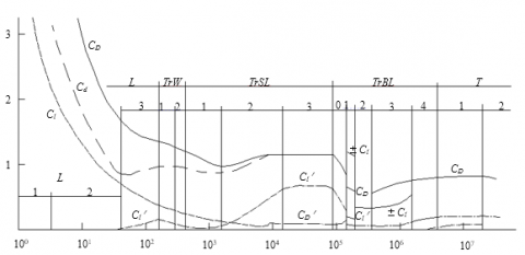
Based on the fluid characteristics of the separation shear layer and the near surface boundary layer of the column, Zdravkovich [11] divided the flow around the smooth cylinder into 15 flow zones (Figure1).
It can be seen from Figure 1 that the lift coefficient of the column is small when 1×10³<Re<1×10⁴ (TrSL1, TrSL2), but it increases rapidly with the increase of Re. When 1×10⁴<Re<1×10⁵, the wake flow regime is located at the tail of TrSL2 and in TrSL3, resulting in a flat segment on the lift curve. When Reenters the interval of 1×10⁵~1×10⁶, the wake flow regime lies in TrBL and the lift curve of the cylinder fluctuates dramatically. This curve segment corresponds to the transition of the boundary layer. Plus, the turbulent boundary layer adds to the stress in the wake flow. The galloping of the regular triangular prism is the result of the variation in the attack angle, and the attack angle of the incoming flow is closely related to the wake flow pattern of the column. Previous research suggests that the installation of rough appendages at symmetrical positions on smooth cylindrical surfaces can effectively trigger boundary layer transition [12-15]. With two symmetrical sharp corners, regular triangular prism does well in separation of the fluid and triggering the boundary layer transition. In light of the above, this paper attempts to discuss the effect of characteristic width on flow-induced vibration and energy transformation of regular triangular prism with elastic supports.
Figure 1. Lift coefficient curve of fixed cylinder
2.1 Test equipment
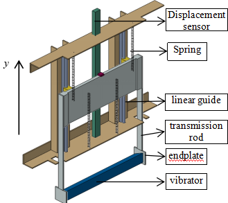
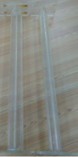
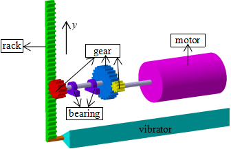
The regular triangular prisms in the test are made of plexiglass. An endplate is installed on each end of the vibrator. The upper end of each endplate is connected to the force transmission device, which is fixed on the linear guide via the connection plate (Figure 2). The amplitude and velocity are measured by a magnetic induction sensor and a Pitot tube flow meter.
Figure 2. The test device
2.2 Vibrator model and vibration system parameters
According to the results in Alonso [7], the column is the least stable when the bottom of the triangular prism is vertical to the direction of the incoming flow. Thus, the regular triangular prism of the test is designed as per the arrangement in Figure 3.
For the purpose of examining the flow-induced vibration and power generation performance of regular triangular prisms of different characteristic widths D, the regular triangular prisms of different characteristic widths D in this test share the same total vibration mass, column length and system stiffness. Figure 4 shows the vibrator and Table1 lists the relevant parameters.
Figure 3. Sectional view of regular triangular vibrator
Figure 4. Regular triangular prism
Table 1. Parameters of the regular triangular prism model
|
Characteristic width D/m |
System stiffness K/(N·m-1) |
Vibrator length L/m |
Total vibration mass Mosc/kg |
Re range |
|
0.08 |
1228 |
0.9 |
27.286 |
0~1.05E5 |
|
0.06 |
1228 |
0.9 |
27.286 |
0~7.94E4 |
The variable damping device used in the test is a DC motor with variable load resistance (Figure 5). The hysteresis damping of the motor is inversely proportional to the load resistance [17].
Figure 5. Sketch map of the variable damping device
Table 2. System damping ratio under different R
|
Load resistance R (Ω) |
Damping ratio ζsystem |
|
10.7 |
0.216 |
|
15.81 |
0.187 |
|
21.82 |
0.164 |
|
32.05 |
0.136 |
|
∞ |
0.089 |
Table 2 describes the ζsystem selected for the test. During the test, the ζsystem is reduced step by step in search of the maximum damping ratios that can be overcome by the galloping regular triangular prisms of different D. The test also investigates the effect of D on the flow-induced vibration performance and the energy transformation of the column.
The Symbols used in the paper are defined in table 3.
Table 3. Symbol definitions and expressions
|
Symbol |
Definition |
Expression |
|
U |
Velocity |
|
|
A |
Amplitude |
|
|
D |
Characteristic width |
|
|
fosc |
Vibration frequency |
|
|
fn |
Natural frequency |
|
|
A* |
Amplitude ratio |
A/D |
|
f* |
Frequency ratio |
fosc / fn |
|
ζsystem |
Damping ratio |
|
|
Ur |
Reduced velocity |
U /(fn·D) |
3.1 Amplitude and frequency response
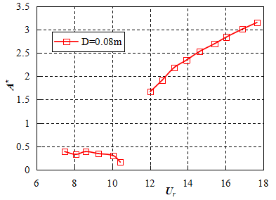
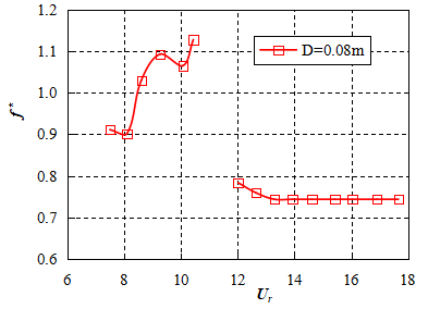
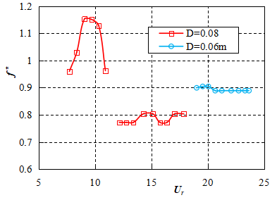
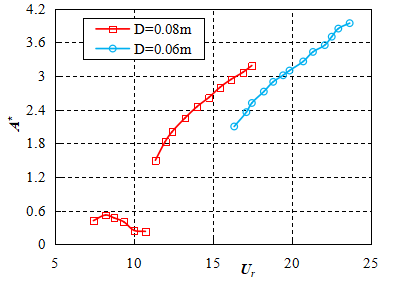
When ζsystem>0. 187, regular triangular prisms of D=0.08m and 0.06m are not subjected to any form of flow-induced vibration within the test velocity range. When ζsystem falls to 0.187, the D=0.08m column begins to undergo flow-induced vibration, while the D=0.06m column is still free from any flow-induced vibration. The response-amplitude ratio (A*=A/D) and frequency ratio (f*=fosc/fn) are displayed in Figure 6. When ζsystem≤0.164, both columns are vibrating (Figures 7~9). The dotted lines stand for the initial amplitude (1.5D) applied to the columns by the external force. Due to the difference in D between the columns, the flow-induced vibration performance of the columns is analyzed by the reduced velocity Ur=U/(fn·D) [5]. The natural frequency of the system is measured by the free attenuation test in the air.
The test results show that the D=0.08m regular triangular prism can gallop against much higher ζsystem than that of D=0.06m column, and the A* of column increases with D under the same Ur. This means larger D enables the regular triangular prism to gallop against higher maximum damping ratio and obtain a larger A*.
(a) Amplitude ratio
(b) Frequency ratio
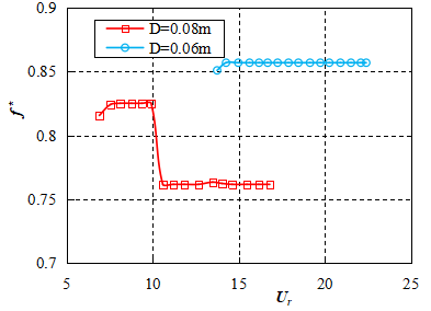
Figure 6. Amplitude ratio and frequency ratio of regular triangular prisms of different D at ζsystem=0.187
As ζsystem=0.187, the variation in A* of the D=0.08m column with Ur appears as two disconnected curves. Without the initial amplitude applied by the external force, the flow-induced vibration of the column bears a resemblance to the VIV of a single cylinder in that both of them are self-limiting vibrations. As the vibration of the column is suppressed and an initial amplitude of about 1.5D is applied to the column, the column enters the galloping from the lower branch of the VIV segment; in this phase, the galloping belongs to the category of hard galloping [18].
(a) Amplitude ratio
(b) Frequency ratio
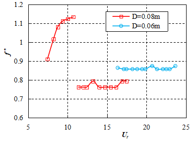
Figure 7. Amplitude ratio and frequency ratio of regular triangular prisms of different D at ζsystem=0.164
(a) Amplitude ratio
(b) Frequency ratio
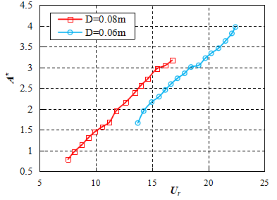
Figure 8. Amplitude ratio and frequency ratio of regular triangular prisms of different D at ζsystem=0.136
(a) Amplitude ratio
(b) Frequency ratio
Figure 9. Amplitude ratio and frequency ratio of regular triangular prisms of different D at ζsystem=0.089
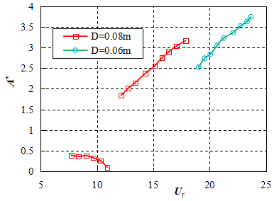
When 0.136≤ζsystem≤0.164, the D=0.08m column undergoes hard galloping. As the ζsystem gradually decreases to 0.089, the D=0.08m column begins to suffer self-excited galloping. The D=0.06m column enters flow-induced vibration from ζsystem=0.164. Within the ζsystem range of this test, the D=0.06m column is not subjected to any vortex-induced vibration. Under the 1.5D initial amplitude applied by the external force, the column moves directly from the state of suppressed flow-induced vibration to the galloping state as the velocity increases. From Figures 6~9, it can be seen that the reduced velocity corresponding to the starting vibration of the column always decreases with the increase of characteristic width.
According to the test results, the amplitude has to meet a critical value for the galloping of regular triangular prism with elastic supports. If the maximum amplitude of the column in the VIV reaches or exceeds the critical value, the galloping of the column is self-excited; otherwise, the column is under hard galloping. For the D=0.08m column, the Re of the test mainly falls in the TrSL3 and TrBL0 regions, and the column is subjected to a large lift coefficient. Under high Re, the shear layer vortex at the near-wake flow of the column becomes smaller, and the formation distance of the vortex is shortened; the ensuing turbulence of the column is massive near the wake flow, which leads to greater velocity fluctuation and Reynolds stress [15-16]. Thus, regular triangular prism with larger characteristic width can gallop against greater damping and obtain higher amplitude. In comparison, the D=0.06m column has a small Re. Under small velocities, the Re of the column rests in the TrSL2 region, and the lift resulted from the vortex shedding is insufficient to excite the VIV of the column against the system damping. As the velocity further grows, the Re of the column starts to enter the TrSL3 region. The column may gallop under the effect of the initial amplitude.
Figures 6~9 also demonstrate the great impact of D on the f* of the column. After the column enters the galloping phase, the f* of the column will decrease with the increase of D. With a small Re and low turbulence at the wake flow, the D=0.06m column boasts much more stable frequency ratio f* in the galloping branch than other regular triangular prisms of large characteristic widths. The stable frequency ratio helps the column output electrical energy with stable frequency.
3.2 Generated power and generating efficiency
This section examines the generated power PAVG and generating efficiency ηAVG of regular triangular prisms with different elastic supports at various Ds under the optimal generating damping ratio. For the VIVACE system, the optimal generating damping ratio is the maximum ζsystem overcome by the galloping column [3]. The results of flow-induced vibration test indicate that the optimal damping ratios of regular triangular prisms of D=0.08m and 0.06m are 0.187 and 0.164, respectively. The PAVG and ηAVG of columns of different Ds under their respective optimal generating damping ratios are calculated according to formulas (1) ~ (3).
Instantaneous power:
$P(t)=\frac{u^{2}(t)}{R_{L}}$ (1)
where u(t) is the instantaneous voltage, V; RL is the load resistance, Ω。
The average output power of a vibration cycle:
$P_{A V G}=\frac{1}{T} \int_{0}^{T} P(t) d t=\frac{1}{T} \int_{0}^{T} \frac{u^{2}(t)}{R_{L}} d t$ (2)
The generating efficiency is expressed as:
$\eta_{A V G}=\frac{P_{A V G}}{P_{w}}=\frac{P_{A V G}}{\left(0.5 \rho U^{3} D L\right)}$ (3)
where Pw is the fluid power, W.
The calculated results are shown in Figures 10 and 11. The PAVG and ηAVG should be calculated under the actual velocity U to measure the actual use value of regular triangular prisms of different D [5].
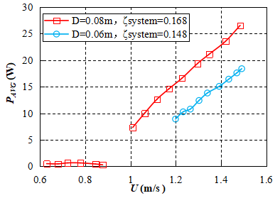
Figure 10. Generated powers of columns of different characteristic widths under the optimal damping ratio
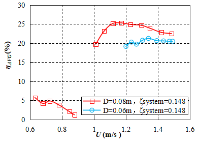
Figure 11. Generating efficiencies of columns of different characteristic widths under the optimal damping ratio
According to Figure 10 and Figure 11, the PAVG and ηAVG of the generator are positively correlated with the D of the regular triangular prism with elastic supports. It follows that increasing the D of the column helps to improve the unit capacity and energy transformation efficiency of the generator. The improvement is realized in the following steps: larger D brings about higher Re of the wake flow of the column; the higher Re raises the maximum system damping ratio surmountable by the galloping column; the large optimal system damping ratio can improve the PAVG and ηAVG of the generator. Through the test, it is concluded that the maximum PAVG of D=0.08m column and D=0.06m column are 26.54W and 18.39W, respectively, and the maximum ηAVG of the two columns are 25.30% and 21.25%, respectively. The maximum ηAVG have surpassed the upper limit efficiency of the single cylinder (ηUL=22%) [5].
This paper discusses the influence of characteristic width on the flow-induced vibration and energy transformation performance of regular triangular prism. The conclusions are as follows:
(1) The research reveals the effect of characteristic width on the response characteristics of regular triangular prism with elastic supports to flow-induced vibration: Larger characteristic width can increase the Re of the wake flow of the column, and the higher Re helps regular triangular prism with elastic supports overcome larger damping and obtain higher response-amplitude ratio; the vibration-starting reduced velocity always decreases with the increase of characteristic width. In the galloping branch, the maximum response-amplitude ratio attainable by the column is negatively correlated with the characteristic width. Besides, the response-amplitude ratio is more stable in the column of smaller characteristic width in the galloping branch.
(2) The author illustrates the advantages of the regular triangular prism of large characteristic width in power generation: larger characteristic width of the regular triangular prism is helpful to improve the optimal generating damping ratio of the column, thus elevating the unit capacity and energy transformation efficiency of flow-induced vibration generator. With regular triangular prism as the vibrator, the flow-induced vibration generator outperforms the cylindrical vibrator-based generator in every aspect from the applicable velocity range, generating quality, unit capacity to energy transformation efficiency. Suffice it to say that the energy transformation device with regular triangular prism as the vibrator enjoys a broad application prospect.
[1] Blevins R.D. (1990). Flow-induced vibration, Van Nostrand Reinhold, New York, pp. 11-12.
[2] Lorenzini G., Lara M.F.E., Rocha L.A.O., Das Neves G.M., Dos Santos E.D., Isoldi L.A. (2015). Constructal design applied to the study of the geometry and submergence of an oscillating water column, International Journal of Heat and Technology, Vol. 33, No. 2, pp. 31-38. DOI: 10.18280/ijht.330205
[3] Seth G.S., Tripathi R., Sharma R. (2015). Natural convection flow past an exponentially accelerated vertical ramped temperature plate with hall effects and heat absorption, International Journal of Heat and Technology, Vol. 33, No. 3, pp. 139-144. DOI: 10.18280/ijht.330321
[4] Bernitsas M.M., Raghavan K., Ben-Simon Y. (2008). VIVACE (vortex induced vibration aquatic clean energy): a new concept in generation of clean and renewable energy from fluid flow, Journal of offshore mechanics and arctic engineering-transactions of ASME, Vol. 130, No. 4, pp. 041101-041115. DOI: 10.1115/1.2957913
[5] Bernitsas M.M., Ben-Simon Y., Raghavan K. (2009). The VIVACE converter: model tests at high damping and Reynolds number around 105, Journal of offshore mechanics and arctic engineering-transactions of ASME, Vol. 31, p. 011102. DOI: 10.1115/OMAE2006-92652
[6] Alonso G., Meseguer J. (2006). A parametric study of the galloping stability of two-dimensional triangular cross-section bodies, Journal of Wind Engineering and Industrial Aerodynamics, Vol. 94, pp. 241-253. DOI: 10.1016/j.jweia.2006.01.009
[7] Alonso G., Meseguer J., Pérez-Grande I. (2007). Galloping stability of triangular cross-sectional bodies: a systematic approach, Journal of Wind Engineering and Industrial Aerodynamics, Vol. 95, pp. 928-940. DOI: 10.1016/j.jweia.2007.01.012
[8] Ding L., Zhang L., Wu CM. (2015). Flow induced motion and energy harvesting of bluff bodies with different cross sections, Energy Conversion and Management, Vol. 91, pp. 416-426. DOI: 10.1016/j.enconman.2014.12.039
[9] Roshko A. (1961). Experiments on the flow past a circular cylinder at very high Reynolds number, Journal of Fluid Mechanics, Vol. 10, NO. 3, pp. 345-356. DOI: 10.1017/S0022112061000950
[10] Raghavan K., Bernitsas M.M. (2011). Experimental investigation of Reynolds number effect on vortex induced vibration of rigid circular cylinder on elastic supports, Ocean Engineering, Vol. 38, pp. 719-731. DOI: 10.1016/j.oceaneng.2010.09.003
[11] Zdravkovich M.M. (1997). Flow Around Circular Cylinders Volume 1: Fundamentals, Oxford Science Publications, Oxford, pp. 21-22.
[12] Prasath S.G., Sudharsan M., Kumar V.V. (2014). Effects of aspect ratio and orientation on the wake characteristics of low Reynolds number flow over a triangular prism, Journal of Fluids and Structures, Vol. 46, pp. 59-76. DOI: 10.1016/j.jfluidstructs.2013.12.008
[13] Chang C.C. (2010). Hydrokinetic energy harnessing by enhancement of flow induced motion using passive turbulence control, Ph.D. dissertation, University of Michigan, Ann Arbor.
[14] Chang C.C. Kumar R.A., Bernitsas M.M. (2011). VIV and galloping of single circular cylinder with surface roughness at 3.0×10⁴≤Re≤1.2×10⁵, Ocean Engineering, Vol. 38, NO. 16, pp. 1713-1732. DOI: 10.1016/j.oceaneng.2011.07.013
[15] Park H., Kumar R.A., Bernitsas M.M. (2013). Enhancement of flow-induced motion of rigid circular cylinder on springs by localized surface roughness at 3.0×10⁴≤Re≤1.2×10⁵, Ocean Engineering, Vol. 72, pp. 403-415. DOI: 10.1016/j.oceaneng.2013.06.026
[16] Unal M.F., Rockwell D. (1988). On vortex formation from a cylinder: the initial instability, Journal of Fluid Mechanics, Vol. 190, pp. 491-512. DOI: 10.1017/S0022112088001429
[17] Guo Z., Zhang J.S., Zheng C.M., Sun Z.C. (2016). Dynamic performance analysis of the induction motor drive fed by current-source based on Ansoft, Modelling, Measurement and Control A, Vol. 89, No. 1, pp. 118-129.
[18] Ding L. (2013). research on flow induced motion of multiple circular cylinders with passive turbulence control, Ph.D. dissertation, Department of the Numerical Simulation and Experimental Verification of the Single Cylindrical Flow Induced by Rough Surface, Chongqing University, Chongqing, China.