OPEN ACCESS
Shape and structure are key factors in the optimal sizing of engineered products, and the constructal theory provides the conceptual framework for achieving this design objective. This paper is concerned with the constructal optimization of a small size linear motor (actuator) that is using a cylindrical Terfenol-D magnetostrictive core (TD-MC). The system under optimization is the TD-MC, subjected to magnetic field and the mechanical stress produced by the inverse Villari effect. The two phenomena are coupled, which makes the optimization problem more difficult. The TD-MC (material) structure is a design input data, therefore the only degree of freedom in morphing the active core is its shape.
We present a mathematical model that describes the electromagnetic field – structure interactions that is used for numerical simulations aimed at identifying the optimal shape for the active MC. Both no-load and load steady state working conditions are considered for several MC cores sizes with different aspect ratios. The MC premagnetization is provided altogether with the actuation by the electrical current in the motor winding.
Intensive numerical work shows off optimal shapes for the MC for a specific structural actuator design.
Magnetostriction, Shape, Constructal, Numerical modeling.
Magnetostriction is a property of ferromagnetic materials that deform, either expand (positive effect) or contract (negative effect), when subjected to a longitudinal, external magnetic field, in the direction of the field [1]. Microscopically, this unidirectional distortion may be due to the spin-orbit mutual potential energy, a function of the distances between atoms and the direction of magnetization [2, 3]. The activation of a magnetostrictive material (MSM) supposes a longitudinal “mechanical bias” such that an external magnetic field may produce the rotation of the magnetic domains, which results in the largest deformation possible. Recently, so-called “giant” magnetostrictive materials, useable in actuating devices, were produced. In particular, Tb0.3Dy0.7Fe1.9, commercially called Terfenol-D, shows off positive magnetostriction å = 1000...2000 ppm at room temperature, for magnetic field strength in the range 50...200 kA/m [4]. In such applications, MSMs are part of magnetic circuits that convey fascicular magnetic fluxes. Electric currents are used then to control the deformation of the active MSM part of the magnetic core [5-8].
The MSM active state depends on the pre-magnetization and mechanical pre-stress conditions. Premagnetisation is commonly produced by permanent magnets while mechanical springs are used for the mechanical pre-stress.
G-MS materials are rather expensive and the actuators have to be as compact as possible, therefore the optimization of the magnetic circuit, of which the G-MS core is part, is a design primary task. Along this line, it follows that the optimization of the MS volume itself is a design goal.
This work is concerned with the optimization of a small size G-MS actuator that utilizes electrical current for pre-magnetisation and excitation. In view of the Constructal Law [9], the shape and the structure of the finite size system (the MC) are the degrees of freedom that may change in morphing to reach a state that complies, as optimally as possible, subject to magnetic and mechanical constraints. Since the structure is a given feature, the shape is then the available optimization parameter for the MS core (MC).
The internal “flows” in the MC are the magnetic flux density fascicular flux and the mechanical stress. When excited, the MC deforms and its resulting shape is such that it poses a minimum resistance (reluctance) to the “flows”. The object of this study is to find, for a given G-MSM cylindrical core volume, the optimal initial slenderness ratio (height/radius) that facilitates the largest elongation (axial deformation) possible.
Another design concern is to use an as small as possible amount of G-MSM for a specific, active, mechanical load, because of the MS material costs. This implies an external, supplementary constraint for the MC system.
In what follows we present a mathematical model that describes the electromagnetic field – structure interactions, which is used in numerical simulations with the aim to identify optimal shapes for the G-MSM cylindrical core of the linear actuator.
Such actuators work quasi-statically until the resonance frequency of the system is reached. Both no-load and load working conditions are considered for several MC volumes with different initial slenderness (aspect) ratios in pre-magnetized and pre-stressed but unexcited states.
Intensive numerical work shows off optimal shapes for the G-MSM core for a specific structural design of a linear actuator.
The linear equations of magnetostriction provide a good first approximation [2, 3]. In the low-signal limit less than one-third the maximum strain capability [3], the magnetic circuit (including the MC) works linearly and does not reach saturation, the approach to magnetostriction may rely on the electromagnetic and structural constitutive laws (in axial direction)
$\varepsilon=\frac{\sigma}{E_{H}}+\frac{\mathrm{d} \varepsilon}{\mathrm{d} H_{\sigma}}, B=\sigma \frac{\mathrm{d} B}{\mathrm{d} \sigma_{H}}+\mu_{\mathrm{c}} H$(1)
where B [T] is the magnetic flux density, H [A/m] the magnetic field strength, m [H/m] the magnetic permeability, s [N/m2] is the elastic tension, E the elasticity module, and e the elastic deformation (strain).
Because the cylindrical MC has to fit into the experimental apparatus, some overall bounds for the axial and radial dimensions have to be imposed. The radius and height of the MC may not exceed the sizes of the working space – these are the upper limits.
There is also a lower bound on the radial size of the rod, imposed by the assumption made concerning the linearity of the magnetic circuit. For fixed actuation current, the radius of the core should be larger than some critical value above which this enters the nonlinear part of the magnetization characteristic.
These constraints add to the constant volume hypothesis: the morphing process should keep a constant volume for the MC. It follows that the relative elastic axial deformation is related to a change in the rod radius through
$\varepsilon=\frac{\rho^{2}}{1-\rho^{2}}, \quad \rho=\frac{\Delta R}{R}$(2)
where R is the radius of the cylindrical MC rod, and DR is the elastic radial deformation. The axial and radial deformations are then related, which reduces the number of the degrees of freedom that have to be accounted for in the optimisation process.
Furthermore, eq. (2) shows off a nonlinear relation. Although monotonic, this leaves room for a possible extremum in the axial displacement versus slenderness ratio optimization. In this study we used numerical simulations to draw these curves and, as will be seen, to find possible extrema.
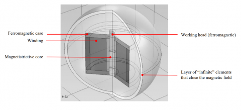
The apparatus utilized in this study is shown in Fig. 1. The working head is pressed by an elastic element against the MC rod. The electric current in the coil is the magnetic field source. The case provides both the return path for the magnetic field and the structural strength of the system. Since steady states only are of concern here, a single coil is used for both pre-magnetization and excitation of the cylindrical MS core.
Figure 1. The G-MSM actuator – the concept apparatus
The physical symmetry of the system and the assumed working conditions may be used, with reasonable accuracy, to simplify the numerical simulations used in the optimization – a 2D axial model instead of a fully 3D one. The stationary magnetic field problem of the MC actuator is described by
$\nabla \times \mathbf{H}=0,$ for the $\mathrm{MC}$(3)
$\nabla \times\left(\mu_{0}^{-1} \mu_{r}^{-1} \nabla \times \mathbf{A}\right)=\mathbf{J}_{\varphi}^{e}, \quad \mathbf{A}=A_{\varphi} \mathbf{e}_{\varphi}$, for the other parts(4)
where A [T.m] is the magnetic vector potential, $\mathbf{J}_{\varphi}^{e}$ [A/m2] the azymuthal component of the electric current density (nonzero within the coil, and zero elsewhere), and H [A/m] the magnetic field strength.
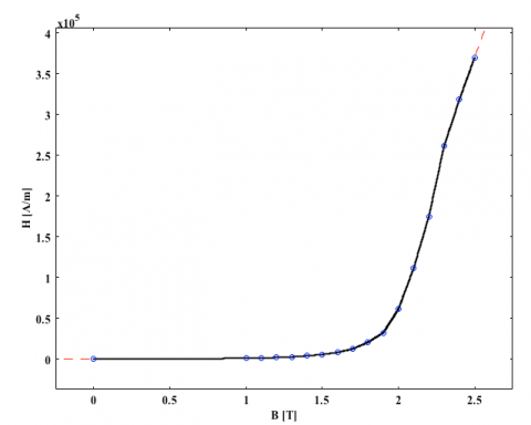
The cylindrical MC is made of Terfenol-D and its magnetization curves are shown in Fig. 2, for the two cases considered here: no load and 3 ksi load.
a. no load
b. 3 ksi load
Figure 2. The magnetization curves for Terfenol-D – after [3]
For modelling convenience, the coil is homogenized within the space that it occupies (a single turn) and an equivalent electric current density is assumed, which provides the same amperturns as the original coil. Its amplitude keeps the magnetic circuit (including the MC) in its magnetic and magnetostriction linear limits.
For the magnetostrictive coefficient we used [7]
$\lambda_{r, z}=\frac{3}{2} \lambda_{S}\left(\alpha_{r, z}^{2}-\frac{1}{3}\right)=\frac{3}{2} \lambda_{S}\left[\left(\frac{M_{r, z}}{M_{S}}\right)^{2}-\frac{1}{3}\right]$(5)
which implies a linear dependence on the magnetic field and the mechanical pre-stress. Here lr,z is the magnetostriction coefficient in Or and Oz directions. It depends on the magnetostriction constant, lS, and on the direction of magetization.
The boundary conditions for the magnetic field problem are as follows: symmetry by the Oz axis, and magnetic insulation (A×n = 0, where n is the outward pointing normal) for the rest of the boundary.
The model for the axial deformation is the generalized Hooke law
$[\sigma]=[C]\left\{[\varepsilon]-\left[\varepsilon_{i}\right]\right\}+\left[\sigma_{i}\right]$(6)
which is applied to the MC only because this part may experience large deformations. In (6), [C] [N/m] is the stiffness, [ε] [m] the elongation, [εi] [m] the initial elongation, [σ] [N] the stress, and [σi] [N] the pre-stress. The MC is assumed to be in a pre-stressed state with the aim to provide a significant magnetostrictive effect.
The boundary conditions that close the stress-strain problem are as follows: the bottom part of the G-MSM rode is “fixed”, its sides have “roller” type conditions, and the top part “load”, either no-load, or 3 ksi uniform load. Symmetry is used for the boundary at r = 0.
The mathematical model (1) – (6) is solved numerically, in the finite element (FEM) technique [10]. The unstructured FEM mesh is made of quadratic Lagrange elements. The same basis of representation is used for the magnetic and mechanical quantities. A layer of “infinite” elements shells the computational domain to close the magnetic field within a finite distance from the actuator.
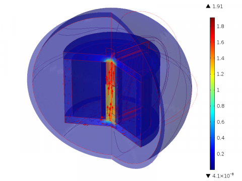
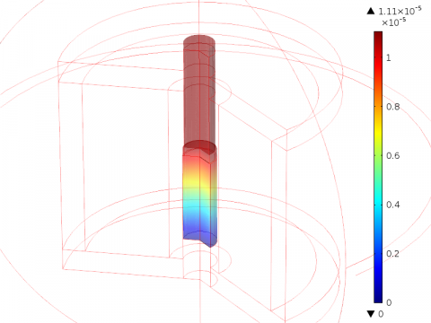
Fig. 3 presents the magnetic flux density and Fig. 4 shows the deformation field for no load working conditions, for the MC with the reference volume. It should be noticed that the magnetic circuit works in the linear regime (B < 2 T).
Several cases are considered, for no-load and load working conditions. Cylindrical MCs with different volumes and of different slenderness ratios were analysed, with the aim to find those sizes and shapes that produce largest axial deformations.
The excitation current is kept constant, and the magnetic circuit of which the MC is part was unchanged.
Figure 3. The magnetic flux density (values are in [T]) – no load
Figure 4. The displacement (values are in [m]) – no load
Figure 5. The axial elongation for different slenderness ratios and different MC volumes. No load working conditions
First, we selected a reference MS core, Vref = 240 mm3. Numerical simulations were conducted for a range of slenderness ratios, K = L/R. The height and radius of the cylindrical core are not to exceed the overall limits Rmax = 4 mm, and Lmax = 25 mm, and also the limits imposed by the linear magnetic and mechanical behaviour.
Then, the simulations where repeated for MCs of other volumes: 2 Vref, 3 Vref/ 2, Vref, 2 Vref/ 3. Fig. 5 presents the results for no-load working conditions.
Qualitatively, the curves change shape as the inflection (change in curvature) seen for the graphics of 2 Vref down to Vref, for K ~ 7 vanishes. The maximum deformation, dmax ~ 32 mm, corresponds to the most slender shape for all cases.
Apparently, the MS core with the smallest volume, Vref/2, may provide the same maximum axial deformation as the MC of 2 Vref volume.
In Fig. 6 the displacements are plotted versus the volume and the slenderness ratio is a parameter.
Figure 6. The axial elongation for different MCs volumes and different slenderness ratios. No load working conditions
This presentation unveils the existence of maximum elongations for MCs with smaller K (K < 6) that are obtainable for MCs of smaller volume, less than Vref. Again, smaller quantities of MS material may work better than larger ones, which may result in costs reductions.
Similar results are obtained when the actuator is loaded. It is important to mention that the displacements obtained through numerical simulations (less than 1700 ppm) are in good agreement with the data provided by the Terfenol-D manufacturer [4].
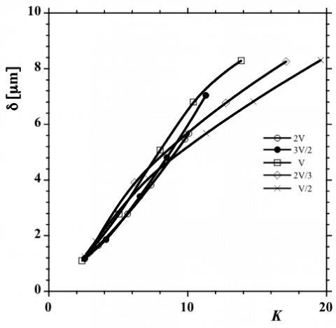
Fig. 7 presents the axial deformation versus slenderness ratio, for different MC volumes.
Figure 7. The axial elongation for different slenderness ratios and different MC volumes. The actuator is loaded with 3 ksi
As expected, the deformations are smaller. The change in shape from small to large K is also remarkable, but the inflection points are less grouped around a certain value of K. The same results are plotted differently in Fig. 8.
Figure 8. The axial elongation for different MC volumes of different slenderness ratios. The actuator is loaded with 3 ksi
Here, unlike the no-load case results here there exist maximum elongations for all slenderness ratios. Larger maximum elongations require larger MC volumes and larger slenderness ratios. This is an important result for the designer.
This paper was concerned with the optimization of a small size G-MSM linear actuator in view of the constructal law. The shape and structure of the finite size MC (the system) may change in morphing the system to reach a state that complies, as optimally as possible, with internal (magnetic and mechanical) and external (mechanical load) constraints. Since the structure is a given, material feature, the shape is the optimization parameter left for the MC.
The internal “flows” within the MC are the fascicular magnetic flux density and the mechanical stress. The MC deforms such that its shape corresponds to a minimum resistance (reluctance) to these flows.
More technically, the object of the study was to find the optimal initial slenderness ratio (height / radius) that leads to the largest elongation (axial deformation) possible for different MS cylindrical cores.
A second concern was the volume of the MC, because of its costs: the smaller amount of G-MSM for a specific mechanical load the cheaper is the actuator.
The numerical simulations were aimed at identifying optimal shapes for the MS core. Both no-load and load working conditions (3 ksi) were considered, for several MC volumes with different initial slenderness (aspect) ratios, in pre-magnetized and pre-stressed, unexcited states. The main finding is the existence of maximal elongations for load and, within a limited range of MC volume, for no-load working conditions. These results indicate that higher elongations are obtained for more slender MCs for increasing MC volumes.
This work was conducted in the Laboratory for Multiphysics Modelling of the Faculty of Electrical Engineering at UPB. The support offered through the grant of the Romanian National Authority for Scientific Research, Program for research – Space Technology and Advanced Research – STAR, project number 88/2013 is acknowledged.
1. Joule, J.P., “On the effects of magnetism upon the dimensions of iron and steel bars,” The London, Edinburgh and Dublin Philosophical Magazine and Journal of Science (Taylor & Francis), 30, Third Series: 76–87, 225–241, 1847. Source: http://en.wikipedia.org/wiki/Magnetostriction.
2. Magnetostriction with the Michelson interferometer, http://www.physics.nus.edu.sg/~L3000/Level3manuals/Magnetostriction.pdf.
3. Calkins, F.T. and Flatau, A.B., Terfenol-D Sensor Design and Optimization, Aerospace Engineering and Engineering Mechanics Department, Iowa State University, Ames, IA 50011, https://www.iea.lth.se/mek/Mekatronikkursen%202006/Energy%20Flow%2006/Magnetostriction.pdf, retrieved in April 2015. DOI: 10.1.1.145.4635.
4. ETREMA Products, Inc., Terfenol-D data sheet.
5. Claeyssen F., Lhermet N., Maillard T., “Magnetostrictive actuators compared to piezoelectric actuators,” Cedrat Technologies ASSET 2002.
6. Atulasimha J., Flatau A.B., “A review of magnetostrictive Iron-Gallium alloys,” Smart Materials and Structures, 20, 2011, DOI: 10.1088/0964-1726/20/4/043001.
7. Pîslaru-Dănescu L., Morega A.M., Morega M., “A novel magnetostrictive injection actuator based on new giant magnetostrictive materials,” The 7th International Symposium on Advaced Topics in Electrical Engineering, ATEE 2011, 12-14 May 2011, Bucharest, IEEE Xplore. ISBN: 978-1-4577-0507-6.
8. Morega, A.M., Marius, P., Morega, M., “Optimizarea unui actuator magnetostrictiv,” Simpozionul de Maşini Electrice, SME-14, University POLITEHNICA of Bucharest, 3 October, 2014. ISSN: 1843-5912.
9. Bejan, A., Shape and Structure, from Engineering to Nature, Cambridge University Press, 2000. ISBN: 0-521-79388-2.
10. COMSOL Multiphysics 3.5a, …, 5.1, COMSOL A.B. Sewden, 2010-2015.