OPEN ACCESS
Air-conditioning in summer is usually carried out through electrically driven devices based on vapor compression cycles. However, an alternative to such conventional applications is the adoption of thermally driven chillers, powered by free thermal energy made available from waste heat or solar thermal systems. In this context, this paper examines the performance of an air-conditioning system for office applications, based on a low capacity water-cooled LiBr/water absorption chiller. The scope is to identify the role of some operating conditions, such as the feeding temperature to the absorption cooling system and the rotation speed of the fan in the cooling tower. The possibility of driving the absorption machine through hot water produced by means of a solar thermal system is also considered. The analysis is carried out in dynamic conditions by using the simulation platform SimSpark, based on a general model already validated through experimental data. The results provide useful suggestions for the design and the operation of solar-assisted absorption cooling systems.
(Presented at the AIGE Conference 2015)
Absorption chiller, Solar cooling, Primary energy consumption, Control logic.
In recent years, the electricity consumption for the air conditioning in buildings has relevantly increased, due to the intensive spread of low-cost units used in residential applications. As an alternative to conventional electrically driven air conditioning systems, based on vapour compression cycles, there has been a growing interest in the use of thermally driven chillers (TDC). In fact, the thermal energy needed to operate such devices can also be provided by waste heat or through solar thermal systems, thus allowing a consistent reduction in the primary energy consumption. Other thermally-driven cycles are based on the use of desiccant materials, are less widespread at the moment, especially in residential buildings [1].
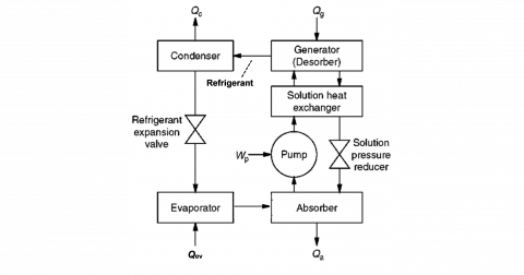
Nowadays, thermally driven chillers are mainly based either on the absorption or on the adsorption principle. However, the dominating technology is by far represented by absorption chillers. In this case, the basic physical process consists of at least two chemical components, one of them serving as the refrigerant and the other as the sorbent [2]. The refrigerant is released as a vapour in the generator (see Fig. 1), where driving temperatures of 80-100°C are typically required. The driving heat (Qg) can be provided by direct fire, or more frequently through hot water produced by a separate device, such as a gas-fired heat generator. After producing the useful effect at the evaporator (Qev), the refrigerant is captured by the sorbent in the absorber: this process is driven by heat rejection to the environment (Qa) [3].
Figure 1. Simplified scheme of the absorption cycle
The basic cycle shown in Fig. 1 is typical of the so-called single effect machines, in which for each unit mass of refrigerant that evaporates in the evaporator, one unit mass of refrigerant has to be desorbed from the solution in the generator [2]. Under normal operating conditions, a single effect absorption machines can achieve a performance index of about 0.7, measured as the ratio of the useful cold production (Qev) to the driving heat (Qg).
As concerns the sorbent-refrigerant pair, the absorption chillers in air conditioning applications mainly use the pair LiBr/water, where water is the refrigerant and LiBr the sorbent. On the other hand, industrial high-capacity absorption chillers are mostly based on the water/ammonia pair, where ammonia is the refrigerant and water is the sorbent. Absorption chillers are available on the market in a wide range of capacities, and designed for different applications. However, only few systems are commercially available in the range below 30 kW [2].
It is also important to remark that the capacity of an absorption chiller is highly dependent on the operating conditions, and in particular on the feeding temperature to the generator. An important role is also played by the temperature at which waste heat can be rejected (Qa + Qc, see Fig. 1). Some indications about the capacity control of absorption chillers can be found in Ref. [4] and Ref. [5].
Absorption chillers can be conveniently powered by thermal energy derived from a solar thermal system. Indeed, the cooling demand and the availability of solar irradiation are positively correlated in time and intensity. Moreover, the temperature level required at the generator is well adapted to the common performance of flat-plate or evacuated-tube solar collectors, the cost of which is nowadays relatively low [6]. A review on solar assisted thermally driven technologies is presented in [7].
This paper studies the performance of an air conditioning system based on a low capacity water-cooled LiBr/water absorption chiller, with the aim to identify the role of the main operating conditions. The analysis is carried out in dynamic conditions, based on a general model already validated through experimental data. The comparison with a conventional air-cooled vapour compression chiller provides interesting advice for an effective exploitation of the absorption technology in residential applications.
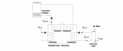
The air conditioning system considered in this study is described in Fig. 2. The absorption chiller is powered by hot water, which, in a first step, is thought to be produced by a gas-fired heat generator. Heat rejection is performed by means of a water flow, which is cooled down through a wet cooling tower. The chilled water produced by the absorption machine is sent to a fan-coil unit for the cooling of a room.
In particular, the absorption chiller corresponds to a model that was on the market up to some years ago, namely the “Solar 045” developed by Rotartica. It is a single stage LiBr/water absorption chiller with a nominal cooling capacity of 4.5 kW, measured at the following operating conditions:
•Water inlet temperature at generator: Tin_g = 90°C
•Water outlet temperature at evaporator: Tin_FC =12°C
•Cooling water inlet temperature: Tin_rej =30°C
The Rotartica chiller has some special features: the absorption cycle is carried out into a hermetically welded spheroid container of approximately 500 mm diameter and 500 mm long, rotated at 550 rpm around a horizontal axis, as described in [9]. The rotation of the components improves the heat transfer coefficients and the efficiency of the cooling production, but an additional electricity consumption is needed to maintain the rotation. Furthermore, there is no internal solution pump, as the pumping power is generated by rotation, i.e. by converting the kinetic energy at the outer radius of the vessel into pressure. Further information on the Rotartica chiller has been reported in [10].
Figure 2. Simplified scheme of the installation [8]
In the proposed air conditioning system, the electricity consumption is due to the Rotartica machine itself (400 W), the cooling tower (370 W) and the pumps on the heat rejection circuit and the generator circuit (200 W). The electricity consumption for the distribution of the chilled water and the fan-coil unit is not taken into account, since it is not directly related to cold production [6].
The behaviour of the system described in Fig. 2 has been simulated in dynamic conditions through a mathematical model implemented on the simulation platform SimSpark. The mathematical model for the absorption machine has been described and validated in [11]; it is based on simple mass and energy balances written on the single components of the machine, and it accounts for their transient behaviour and their thermal inertia. The cooling tower has been modeled through the well-established equations reported in [12]. The room and the fan-coil unit can be described through simple energy balances, once the thermal load and the air flow rate through the fan-coil unit are assigned (1700 m3/h).
On the whole, the mathematical model needs, as input data, the inlet temperature of the hot water to the generator, the outdoor air temperature and relative humidity and the thermal load of the room. Other data concerning the operation of the absorption system, e.g. the water flow rates to all the components, can be found in [11].
In the simulations, the system is equipped with a thermostatic control aimed at keeping the indoor dry-bulb air temperature between 25°C and 27°C; this means that all the energy consuming components – pumps, fan-coil unit, cooling tower, absorption machine – are switched off when the room temperature gets lower than 25°C, and reactivated if it exceeds 27°C. However, according to the manufacturer, the Rotartica machine does not immediately turns off, but it keeps operating for about 12 minutes without producing any cooling power, in order to avoid too frequent activation cycles; of course, this practice implies additional electricity consumption.
The behaviour of the system is studied with reference to the mild Mediterranean climate. Such a choice is justified by the wish to test the system in more trying conditions than in continental Europe, as higher environmental temperatures – and higher solar irradiation – should negatively affect heat rejection and imply higher thermal loads than in cold climates. The simulations are performed over five identical hot and sunny days; Fig. 3 shows the outdoor dry-bulb temperature adopted in the simulations for one of these days, as measured in Catania (Southern Italy).
Figure 3. Room sensible thermal load and outdoor temperature profile adopted for the simulations
Moreover, Fig. 3 also shows the corresponding sensible thermal load of the test room, determined through simulations carried out by Energy Plus on a fictitious office building, which has a peak thermal load close to the nominal cooling capacity of the absorption machine. The simulations are repeated for several values of the generator feeding temperature (from 75°C to 100°C, with a five-degree step), in order to investigate the sensitivity of the overall system performance to this parameter.
In this study, a conventional cooling system was also considered, where an air-cooled vapour compression chiller is used in place of the absorption machine and the cooling tower. This conventional system serves as a reference to determine the actual suitability of the absorption technology. The cooling production and the electricity consumption of the conventional chiller can be assessed as a function of the outdoor dry-bulb air temperature and the chilled water outlet temperature, according to the performance curves provided by the manufacturer [13]. At nominal conditions (35°C outdoor air temperature, 7°C chilled water outlet temperature) the cooling power of the conventional chiller is 5 kW, whereas its electricity consumption is 1.6 kW. Therefore, the nominal Energy Efficiency Ratio, which is the ratio between the two data, is EERnom = 3.1.
Now, in order to evaluate the performance of both systems, the following parameters are assessed [14]:
•Thermal COP of the absorption machine, defined as the ratio of the overall cooling capacity to the overall thermal energy provided to the machine:
$C O P_{t h}=Q_{e v} / Q_{g}$ (1)
•Electrical COP, defined as the ratio of the overall cooling capacity to the overall electricity consumption, omitting the electricity spent on the distribution side:
$C O P_{e l}=Q_{e v} / E_{e l}$ (2)
•Primary Energy Ratio (PER), defined as the ratio of the overall cooling capacity to the overall primary energy required for system operation:
$P E R=\frac{Q_{e v}}{P E_{t o t}}=\frac{Q_{e v}}{P E_{t h}+P E_{e l}}=\frac{Q_{e v}}{\frac{Q_{g}}{\eta_{h g}}+\frac{E_{e l}}{\eta_{e l}}}$ (3)
These parameters are averaged out over the simulation period with the exclusion of the first day, which is affected by the initial conditions. In Eq. (3), the efficiency of the heat generation system is hhg = 0.91, whereas an overall efficiency hel = 0.46 for electricity production and distribution is used.
3.1 The reference system
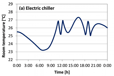
The main results of the simulation concerning the air-cooled vapour compression chiller are summarized in Table 1. Moreover, Fig. 4a reports the time profile of the indoor air temperature that is obtained in the simulated room during a representative day when the conventional air conditioning system is used.
Here, one can observe that not always the air conditioning system is able to prevent the room temperature from getting higher than 27°C, as the room sensible thermal load might be temporarily higher than the cooling power provided by the chiller. On average, the system keeps running for 7.3 hours per day, while during the 17.7% of this time lapse the room temperature cannot be kept under 27°C; however, the maximum value is 27.4°C. The average EER is 3.9, which is pretty higher than the nominal value (EERnom = 3.1), as the chiller operates, on average, at higher chilled water outlet temperature (Tout_ev = 13.9°C, see Table 1) and lower outdoor air temperature (Ta = 31.1°C) than in nominal conditions.
Table 1. Average performance for the electric chiller
|
Qev [kWh/day] |
Eel [kWh/day] |
Time ON [h/day] |
EER [-] |
|
34.7 |
8.9 |
7.3 |
3.9 |
|
PER [-] |
Tout-ev [°C] |
Troom_max [°C] |
fON > 27°C |
|
1. 79 |
13.9 |
27.4 |
17.7 % |
3.2 The absorption system
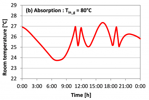
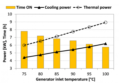
This section describes the results of the simulations for the absorption system, with a parametric analysis about the water inlet temperature to the generator. As one can observe from Fig. 5, as soon as the generator inlet temperature increases the average cooling capacity of the Rotartica absorption machine gets higher. Indeed, if Tin_g = 75°C the average cooling power is 4.4 kW, while it increases up to 6.2 kW for Tin_g = 100°C.
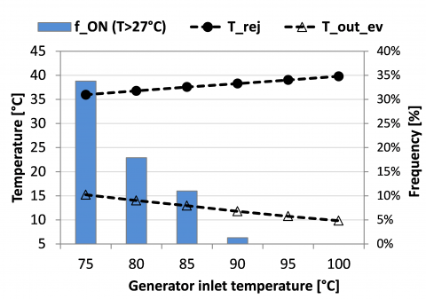
Thanks to the higher cooling capacity, the system can fulfill the indoor air conditioning in a faster and more effective way: indeed, if Tin_g > 80°C the room temperature seldom exceeds 27°C, as observed from the room temperature profiles in Fig. 4c and Fig. 4d. Figure 6 also shows that the frequency of discomfort occurring despite the machine being activated (fON > 27°C) becomes very low for Tin_g > 85°C.
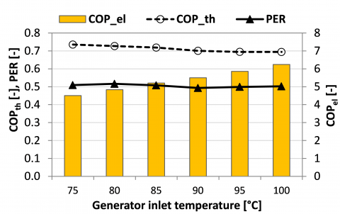
As the room is conditioned more quickly, the machine switches off more frequently. This implies significant energy savings: as an example, at 100°C inlet temperature the system is working 1.5 hours less than at 80°C (see Fig. 5), which means a 21% reduction in electricity consumption. Such a benefit is also reflected by the increase in the electric COP (see Fig. 7), shifting from 4.8 to 6.2.
On the other hand, the choice of a high generator inlet temperature determines some drawbacks, such as the increase in the thermal power needed to feed the absorption machine (see Fig. 5), the rise in the water temperature at the rejection side and the fall in the chilled water temperature (see Fig. 6). All of these effects negatively affect the thermal COP of the Rotartica machine, which stabilizes around COPth = 0.7 for Tin_g > 90°C, as shown in Fig. 7.
Figure 4. Simulated daily profile for the indoor temperature
Figure 5. Average performance of the absorption chiller
Figure 6. Average outlet temperatures and frequency of discomfort in the simulated test room
Figure 7. Average coefficients of performance for the absorption system
The right balance between these two opposite effects resulting from high generator inlet temperatures, namely the reduction in electricity consumption and the increase in thermal energy need, can only be found by looking at more general performance parameters, such as the primary energy ratio (PER). Actually, the PER does not vary significantly with Tin_g (see Fig. 7): the highest values are attained at low generator inlet temperatures, with a peak value of 0.51 at 80°C. Anyway, PER is always very low if compared to the value obtained with the reference system (PERref = 1.79, see Table 1). Hence, it is apparent that the use of a water-cooled LiBr/water absorption chiller for air-conditioning is not a good practice if not assisted by renewable energy sources.
Figure 8. Contributions to the PE consumption
Figure 8 also shows that the greatest part of the primary energy consumption is due to the thermal energy production needed by the absorption machine, with a peak of 82% for Tin_g = 100°C. As opposite, only a little percentage is associated with the electricity consumption of the auxiliary components and the Rotartica machine itself.
As a result, the greatest potential for the improvement of the PER lies in the use of a solar thermal system for hot water production. According to the results discussed so far, it seems suitable to operate the solar thermal system at temperatures around 80-85°C, which would allow higher primary energy ratio and better efficiencies for the solar collectors than at 95-100°C. This issue is discussed in detail in the following section.
3.3 Solar energy as a heat source
Now, let us couple the air conditioning system shown in Fig. 2 to a solar thermal system that may contribute to produce the hot water needed for the activation of the thermally driven chiller.
In this case, let us define solar fraction (SF) the fraction of the overall thermal energy required by the absorption machine that is provided by the solar section [15]. According to this definition, the primary energy demand of the solar assisted air conditioning system is calculated as follows:
$P E_{s o l}=\frac{Q_{g}}{\eta_{h g}} \cdot(1-S F)+\frac{E_{e l}+E_{e l, s c}}{\eta_{e l}}$ (4)
In Eq. (4), Eel,sc is the electricity consumption in the solar section, due to the circulation pumps and the control devices. According to the authors’ experience, such a contribution does not add more than 15% to the electricity consumption of the air conditioning system itself (Eel). It can be roughly assumed proportional to the size of the solar section, hence to the achieved solar fraction:
$E_{e l, s c}=\left(0.15 \cdot E_{e l}\right) \cdot S F$ (5)
Based on these positions, it is possible to assess the minimum solar fraction (SFmin) needed to make the primary energy consumption of the solar assisted system (PEsol) as high as that obtained for the reference system (PEref). Indeed, by using Eq. (4) and Eq. (5) under the condition PEsol = PEref, one gets:
$S F_{\min }=\frac{\left(\frac{Q_{g}}{\eta_{h g}}+\frac{E_{e l}}{\eta_{e l}}\right)-P E_{r e f}}{\frac{Q_{g}}{\eta_{h g}}-0.15 \cdot \frac{E_{e l}}{\eta_{e l}}}$ (6)
Moreover, the maximum potential value for the PER in the solar assisted system can be derived from Eq. (4) and Eq. (5) under the condition SF = 1:
$P E R_{\max }=\frac{Q_{e v}}{1.15 \cdot\left(E_{e l} / \eta_{e l}\right)}$ (7)
However, this value must be interpreted as a threshold. Indeed, it is not technically feasible to get SF = 1 even if installing a very high surface of solar collectors.
Finally, it is interesting to determine the collector surface that should be installed to achieve the minimum solar fraction defined by Eq. (6). Such a value can be assessed by means of Eq. (8).
$A_{\mathrm{sc}, \min }=\frac{Q_{g} \cdot S F_{\min }}{H \cdot \eta_{\mathrm{sc}} \cdot(1-1)}$ (8)
Here, the value of the daily solar irradiation available on the collectors (H = 7.0 kWh m-2 day-1) refers to Southern Italy in summer, by assuming the collectors south-oriented with a 30° slope on the horizontal. The average efficiency of the solar collectors refers to high-efficiency evacuated tube collectors operating in favorable environmental conditions (30°C outdoor temperature, 700 W∙m-2 solar irradiance), as usual in Southern Italy. The role played by the water temperature on the collector efficiency has been taken into account. The percentage heat losses l in the solar circuit (pipes, heat exchanger, storage tank) are estimated as high as 15% of the overall energy gain.
The results of this analysis are summarized in Table 2. As one can observe, increasingly better results may be obtained as the generator inlet water temperature gets higher. Indeed a PER close to 2.4 might be achieved, which means 30% better than what obtained for the reference system. In any case, a minimum collector area around 12 or 13 m2 is needed.
Table 2. Performance of an ideal solar system assisting the absorption machine
|
Generator inlet |
75°C |
80°C |
85°C |
90°C |
95°C |
100°C |
|
SFmin [-] |
0.994 |
0.966 |
0.950 |
0.942 |
0.923 |
0.907 |
|
PERmax [-] |
1.82 |
1.96 |
2.06 |
2.13 |
2.28 |
2.42 |
|
hsc [-] |
0.64 |
0.63 |
0.62 |
0.61 |
0.60 |
0.59 |
|
Asc,min [m2] |
12.1 |
12.1 |
12.5 |
13.1 |
13.2 |
13.3 |
3.4 Control logic for heat rejection
As discussed in the previous sections, a large part of the electricity consumption in the air conditioning system shown in Fig. 2 is caused by the rotation of the internal vessel in the Rotartica absorption machine (400 W) and by the operation of the cooling tower (370 W).
Now, the former contribution cannot be avoided, as it is strictly correlated to the operation of the absorption machine. On the other hand, one might think to reduce the electricity consumption of the cooling tower by varying the rotation speed of the fan by means of a variable-frequency drive, commonly known as inverter. In fact, the reduction in the rotation speed will imply a quasi-proportional decrease in the airflow rate, whereas the electricity absorbed by the fan should decrease proportionally to the third power of the rotation speed.
However, some drawbacks are expected. Indeed, a less effective heat rejection in the cooling tower should raise the return water temperature to the absorption chiller; this would result in a lower cooling capacity and, most likely, in a lower thermal COP than at full rotation speed. In order to make a balance between these conflicting aspects, six different scenarios are studied (two generator inlet temperatures, three values for rotation speed and airflow rate).
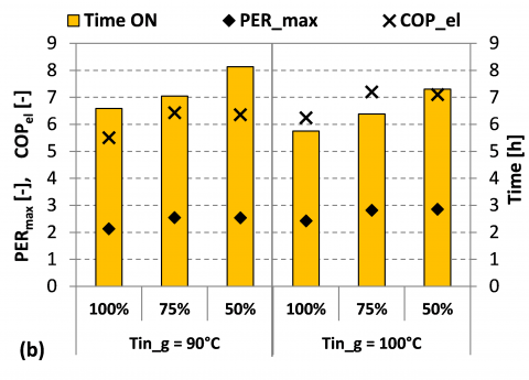
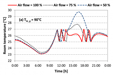
The results of the simulations are reported in Fig. 9 and Fig. 10. First, one can notice the negative effect of an excessive limitation of the rotation speed. Indeed, at 50% a drop in the cooling capacity Qev of the absorption machine occurs (e.g. from 5.4 kW to 4.1 kW at Tin_g = 90°C, see Fig. 9a). This is also witnessed by the corresponding rise in the outlet temperature of the chilled water (from 11.8°C to 16.6°C at Tin_g = 90°C, see Fig. 9a).
Figure 9. Solar assisted absorption chiller: average performance versus airflow rate in the cooling tower
Consequently, the room would not be effectively cooled down, and the percentage of time when comfort conditions are not assured would even exceed 50% (see Fig. 9a).
This problem is also visible from Fig. 10, which shows the simulated indoor temperature profile in the test room: despite the absorption machine being in operation, the indoor temperature approaches 30°C when the rotation speed is reduced to 50% and Tin_g = 90°C. Such operating conditions should then be avoided.
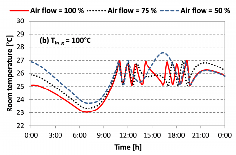
On the other hand, a higher feeding temperature (Tin_g = 100°C) would allow enough cooling capacity even at low rotation speed, and the frequency of uncomfortable indoor conditions would not exceed 20% (see Fig. 9a).
Moreover, there is another unexpected and undesirable effect of an excessive variation in the rotation speed: due to the resulting drop in the cooling capacity, the system is forced to operate for a longer time in order to perform the indoor air conditioning. Indeed, as shown by Fig. 9b, the time of operation (TimeON) increases from 6.6 to 8.1 hours when Tin_g = 90°C. This implies more electricity consumption, which balances the savings determined by the low rotation speed of the fan in the cooling tower.
In conclusion, a rotation speed as high as 75% of the nominal value turns out to be a good compromise between benefits and drawbacks. In this case, the electrical COP (COPel) attains the highest value (see Fig. 9b), and an appropriate control of the indoor temperature is obtained (see Fig. 10). Finally, with a solar assisted system it is possible to get a maximum Primary Energy Ratio (PERmax) of about 2.9 (Fig. 9b), which means 60% higher than the conventional air conditioning system.
Figure 10. Consequences of the variation of the airflow rate in the cooling tower on the indoor air temperature
As shown by the results presented in this paper, the primary energy consumption of an air conditioning system based on the water-cooled low-capacity Rotartica absorption chiller would be far higher than an equivalent system using a conventional air-cooled vapour compression chiller.
This outcome is due to many reasons. First, the relatively low thermal COP of single stage absorption machines, while the EER of the vapour compression chillers currently available on the market is quite high, which makes the competition more difficult for an absorption machine. Then, the need of additional components, such as the cooling tower, absorbing a high amount of electricity, which adds up to that consumed by the Rotartica machine itself. For all these reasons, and apart from economic issues, the integration with a solar thermal system is necessary when using thermally driven air conditioning technologies.
The paper also shows that it is not easy to identify a single feeding temperature that optimizes the system performance under all points of view. Indeed, in order to ensure constantly comfortable conditions indoors, it would be suitable to keep the feeding temperature above 90°C; on the other hand, the highest thermal COP is obtained when feeding the machine at 80°C. In case of a solar-assisted system, the higher is the feeding temperature, the higher the primary energy ratio potentially achievable, provided that a sufficient surface of evacuated tube solar collectors is installed (at least, 13 m2).
The paper also investigates the potentiality of a control logic based on the variation of the rotation speed of the fan in the cooling tower. The results show that, in case of excessive speed reduction, the savings in the electricity consumption determined by lowering the rotation speed would be counterbalanced by a reduction in the cooling capacity, thus making this logic not always profitable. According to the results, it seems suitable not to operate under 75% of the nominal rotation speed.
Obviously, such results refer to a specific water-cooled LiBr/water machine, and cannot be extended to all the cooling systems based on the absorption technology.
|
Symbols |
|
|
A |
Surface (m2) |
|
COP |
Coefficient of Performance (-) |
|
EER |
Energy Efficiency Ratio (-) |
|
Eel |
electric energy (kWh) |
|
f |
frequency (%) |
|
H |
solar irradiation (kWh m-2) |
|
l |
thermal losses (-) |
|
PE |
primary energy consumption (kWh) |
|
PER |
primary energy ratio (-) |
|
Q |
thermal energy (kWh) |
|
SF |
solar fraction (-) |
|
T |
temperature (°C) |
|
η |
ratio of final to primary energy (-) |
|
Subscripts |
|
|
a |
outdoor air |
|
e |
evaporator |
|
el |
electricity |
|
in |
inlet |
|
f |
fuel |
|
FC |
fan-coil unit |
|
g |
generator |
|
hg |
heat generator |
|
nom |
nominal value |
|
out |
outlet |
|
ref |
reference system |
|
rej |
heat rejection |
|
sc |
solar collector |
|
th |
thermal |
|
tot |
total |
1. A. Gagliano, F. Patania, F. Nocera, A. Galesi, “Performance assessment of a solar assisted desiccant cooling system,” Thermal Science, vol. 18(2), pp. 563-576, 2014, DOI: 10.2298/TSCI120526067G.
2. H.M. Henning, “Solar assisted air conditioning of buildings - an overview,” Appl Therm Eng, vol. 27, pp. 1734-1749, 2007, DOI: 10.1016/j.applthermaleng.2006.07.021.
3. B. Prasartkaew, “Performance test of a small size LiBr-H2O absorption chiller,” Energ Proc, vol. 56, pp. 487-497, 2014, DOI: 10.1016/j.egypro.2014.07.183.
4. J. Albers, “New absorption chiller and control strategy for the solar assisted cooling system at the German federal environment agency,” Int J Refriger, vol. 39, pp. 48-56, 2014. DOI: 10.1016/j.ijrefrig.2013.08.015.
5. O. Marc, G. Anies, F. Lucas, J. Castaing-Lasvignottes, “Assessing performance and controlling operating conditions of a solar driven absorption chiller using simplified numerical models,” Sol Energy, vol. 86, pp. 2231-2239, 2012, DOI: 10.1016/j.solener.2012.04.013.
6. M. Pons et al., “Performance comparison of six solar-powered air-conditioners operated in five places,” Energy,
vol. 46, pp. 471-483, 2012, DOI: 10.1016/j.energy.2012.08.002.
7. A. Ghafoor, A. Munir, “Worldwide overview of solar thermal cooling technologies,” Renew Sustain Energ Rev, vol. 43, pp. 763-774, 2015, DOI: 10.1016/j.rser.2014.11.073.
8. G. Evola, L. Marletta, N. Le Pierrès, E. Wurtz, “Parametric analysis aimed at optimizing the control logic of an absorption-based cooling system,” Proc. Int. Sorption Heat Pump Conf., pp. 263-272, 2011.
9. K. Gilchrist, R. Lorton, J.R. Green, “Process intensification applied to an aqueous LiBr rotating absorption chiller with dry heat rejection,” Appl Therm Eng, vol. 22, pp. 847-854, 2002, DOI: 10.1016/S1359-4311(01)00123-5.
10. M. Izquierdo, R. Lizarte, J.D. Marcos, G. Gutiérrez, “Air conditioning using an air-cooled single effect lithium bromide absorption chiller: results of a trial conducted in Madrid in August 2005,” Appl Therm Eng, vol. 28, pp. 1074-1081, 2008, DOI: 10.1016/j.applthermaleng.2007.06.009.
11. G. Evola, N. Le Pierrès, F. Boudehenn, P. Papillon, “Proposal and validation of a model for the dynamic simulation of a solar-assisted single-stage LiBr/water absorption chiller,” Int J Refriger, vol. 36 (3), pp. 1015-1028, 2013, DOI: 10.1016/j.ijrefrig.2012.10.013.
12. J.C. Kloppers, D.C. Kröger, “A critical investigation into the heat and mass transfer analysis of counter-flow wet cooling towers,” Int J Heat Mass Tran, vol. 48, pp. 765-777, 2005, DOI: 10.1016/j.ijheatmasstransfer.2004.09.004.
13. AERMEC technical documentation.
14. R. Lizarte, M. Izquierdo, J.D. Marcos, E. Palacios, “Experimental comparison of two solar-driven air-cooled LiBr/H2O absorption chillers: Indirect versus direct air-cooled system,” Energ Build, vol. 62, pp. 323-334, 2013, DOI: 10.1016/j.enbuild.2013.03.023.
15. R. Gomri, “Simulation study on the performance of solar/natural gas absorption cooling chillers,” Energ Convers Manage, vol. 65, pp. 675–681, 2013, DOI: 10.1016/j.enconman.2011.10.030.