OPEN ACCESS
In this paper, flexible multi-body dynamics was coupled with elastohydrodynamic lubrication of main bearings to study the lubricating properties of diesel engine main bearings. Data of bearing forces for diesel engine main bearings under rated conditions and cylinder 1 misfired conditions were analyzed, to provide a basis for the tribology design of a main bearing friction pair and the system optimization of a diesel engine. The result showed that single cylinder misfire had a greater influence on the two adjacent main bearing loads and the axis orbits of the two adjacent main bearings, but less effect on the other main bearing load and axis orbits of the other main bearings.
Diesel engine, Main bearing, Lubrication, Misfire.
Lubrication systems are very important for Diesel engine [1-5] with good lubricating properties of main bearings able to guarantee stable and reliable diesel engine operation [6-9]. Diesel engine main bearings can run fasterF and bear a larger load [10-13]. Elastic deformation on the surface contact of bearings, as well as the bearings themselves, can affect oil film thickness, oil film pressure, and the force and power consumption of friction, thereby affecting the lubricating properties of the main bearing [14-15]. Therefore, it was not possible to ignore elastic deformation when analysing main bearing lubrication properties. At the same time, an elastic deformation equation was added to the lubrication equation set for a common solution, which belongs to the category of elastohydrodynamic lubrication [16-19].
In this paper, multi-body dynamics of diesel engines was coupled with elastohydrodynamic lubrication of main bearings to study the lubricating properties of main bearings, for the purpose of providing a basis for the tribology design of a main bearing friction pair and for the system optimization of a diesel engine.
2.1 Lubrication model
In the form of average Reynolds equation with oil filing ratio [20]:
$-\frac{\partial}{\partial \mathrm{x}}\left(\cdot \bar{\theta} \cdot \varphi_{x} \cdot \frac{h^{3}}{12 \eta} \cdot \frac{\partial \overline{\mathrm{p}}}{\partial x}\right)-\frac{\partial}{\partial \mathrm{y}}\left(\bar{\theta} \cdot \varphi_{y} \cdot \frac{h^{3}}{12 \eta \cdot} \frac{\partial \overline{\mathrm{p}}}{\partial \mathrm{y}}\right)+ \partial\left(\bar{\theta} \cdot\left(\bar{h}_{T}+\sigma \cdot \varphi_{s}\right) \cdot \frac{u_{1}+u_{2}}{2}\right)\frac{\partial x}{\partial \mathrm{t}}+\frac{\partial\left(\bar{\theta} \cdot \bar{h}_{T}\right)}{\partial x}=0$ (1)
Where: $\bar{\theta}$ was referred to as the oil filling rate, that was, the ratio of the oil film thickness of shaft journal and bearing shell and the clearance height of shaft journal and bearing shell in the bearing friction pair; p was oil film pressure; η was the dynamic viscosity of lubricating oil; u1 was the circumferential velocity of shaft journal; u2 was the circumferential velocity of bearing shell; t was the time; h was the oil film thickness; x and y represented the peripheral direction of bearing; z was the axial direction of the bearing; $\bar{h}_{T}$ was the average value of actual oil film thickness; $\varphi_{S}$ represented the shear flow factor and; .. was the standard deviation of the comprehensive contact surface roughness.
To solve, the following boundary conditions were adopted:
(1)Axial boundary conditions:
$\bar{p}=p_{a}\left(y=\pm \frac{B}{2}\right)$
(2) Circumferential boundary conditions:
(i) Oil film starting side: as $\theta=0$ ,
$\left\{\begin{array}{l}p=p_{n}\left(|x| \leq \frac{1}{2}\right) \\ p=p_{n} \frac{B-2|x|}{B-1}\left(\frac{1}{2}<|x| \leq \frac{B}{2}\right)\end{array}\right.$
(ii) Oil film ending side: as $\theta=\frac{y}{r}, \frac{\partial p}{\partial \theta}=0$ and $p=p_{a}$
(3) Oil supplying area: $\bar{p}=p_{\text {in }}$
(4) Cavitation boundary conditions:
$\left\{\begin{array}{l}\bar{p}>0(\bar{\theta}=1) \\ \bar{p}=0(0<\bar{\theta}<1)\end{array}\right.$
2.2 Contact model
In this paper, the asperity contact model proposed by Greenwood and Tripp was used. In consideration of elastic deformation of the contact body, the contact force was expressed as:
$p_{a}=k \sqrt{\frac{\sigma_{s}}{\beta}} E^{*} F_{5 / 2}\left(h_{S}\right)$ (2)
In which:
$E^{*}=\frac{1}{\left(\frac{1-v_{1}^{2}}{E_{1}}+\frac{1-v_{2}^{2}}{E_{2}}\right)}$
$F_{5 / 2}=\left\{\begin{array}{ll}4.408610^{-5}\left(4-H_{s}\right)^{6.804}, H_{s}<4 \\ 0 , H_{s} \geq 4\end{array}\right.$
$k=\frac{16 \sqrt{2} \pi}{15}\left(\sigma_{s} \bar{\beta} \eta_{2}\right)^{2}$
$\sigma_{s}=\sqrt{\frac{1}{\eta_{s}} \sum_{q=1}^{\eta_{s}} \delta_{s}^{2}}$ ;
In this formula, $F_{5 / 2}\left(H_{s}\right)$ was the function of oil film thickness, that was, to judge whether the bearing was in the state of elastohydrodynamic contact. $E^{*}$ was the overall elasticity modulus. $E_{1}$ and $E_{2}$ were the elasticity modulus of bearings and shaft journal materials, respectively. $v_{1}$ and $v_{2}$ were the Poisson’s ratios of bearings and shaft journal materials, respectively. $k$ was the elastic contact factor and related to the roughness of the materials. Generally, it was difficult to determine and usually in the range $0.0003 \leq k \leq 0.003$ .$\sigma_{s}$ was the comprehensive roughness.
2.3 Flexible multi-body system dynamics model
The motion of the flexible body meets Lagrange equation:
$\left\{\begin{array}{c}\frac{d}{d t}\left(\frac{\partial L}{\partial \dot{\xi}}\right)-\frac{\partial L}{\partial \xi}+\frac{\partial \Gamma}{\partial \dot{\xi}}+\left[\frac{\partial \Psi}{\partial \xi}\right]^{T} \lambda-Q=0 \\ \Psi=0\end{array}\right.$ (3)
In which, $L$ represented the Lagrange equation. Here, $L=T-W$ , where $T$ was kinetic energy and $W$ was potential energy. $\boldsymbol{\Psi}$ represented the constraint equation. $\xi$ represented generalized coordinates. $\lambda$ represented the Lagrange multiplier of the constraint equation. $\boldsymbol{Q}$ was the force of the generalized coordinate system $\xi$ $\Gamma$ represented the energy loss function.
Finally, the differential equation of motion of a flexible body might be written as:
$M \ddot{\xi}+\dot{M} \dot{\xi}-\frac{1}{2}\left[\frac{\partial M}{\partial \xi} \dot{\xi}\right]^{T} \dot{\xi}+K \xi+f_{g}+D \dot{\xi}+\left[\frac{\partial \Psi}{\partial \xi}\right]^{T} \lambda=Q$ (4)
In the formula, $\xi$ represented generalized coordinates. $\boldsymbol{M}$ was the mass matrix. $\frac{\partial \boldsymbol{M}}{\partial \boldsymbol{\xi}}$ was the partial derivative of mass matrix to generalized coordinates. $K$ represented the stiffness matrix. $f_{g}$ was the inertial force. $D$ was the damping matrix. $M$ was the modal number.
2.4 Single-cylinder pressure as misfires
With regard to the lubricating properties of main bearings with single-cylinder misfires, related research work has previously been carried out. Typically, a misfired cylinder was processed as follows: it is assumed that the pressure of the misfired cylinder was opened by the indicator valve of the misfired cylinder to maintain atmospheric pressure. Pressure of the misfired cylinder was handled as follows: there was no fuel burning in the misfire cylinder, but the gas distribution mechanism and crank link mechanism were in normal working states. That is, in the cylinder, the pressure varied with crank angle and the gas still went through the processes of inhaling, compression, expansion and exhaling. Since there was no fuel burning, the mean effective pressure of the misfired cylinder had a negative value; work was consumed rather than created by the misfired cylinder due to mechanical losses.
To solve lubrication problems of main bearings, elastic deformation should be taken into consideration and tribology and multi-body dynamics were coupled with each other. Elastic deformation of shaft journals and bearing shells was solved based on the differential equation of motion. Given load parameters were required with oil film pressure being one of the loads. However, oil film pressure was solved based on the Reynolds equation, provided that oil film thickness was known. Except, the oil film thickness was subject to elastic deformation and so, the dynamics and tribology calculations were the process of interaction and a joint solution was developed. In general, an oil film pressure was given and then multi-body dynamics was calculated in line with the differential equation of motion. The elastic deformation was solved and oil film thickness was obtained. Afterwards, Reynolds equation was solved and oil film pressure was calculated on the basis of obtained oil film thickness, to determine whether initial pressure was correct or not. If it was incorrect, the new oil film pressure was used to solve the differential equation of motion and Reynolds equation until they converged.
4.1 Loading conditions
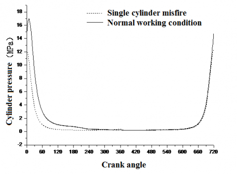
Now, an inline six cylinder was taken as a research object to analyze the lubrication of main bearings through coupling calculation of dynamics and tribology. Diesel engine parameters are shown in Table 1. Data from indicator diagram with 2,000 r/min rated speed was selected as the initial load boundary conditions, as shown in Fig 1. 0°CA of crank angle means Cylinder I was located on the compression Top Dead Center (TDC). Single-cylinder pressure during misfires was computed by conditions and parameters of the diesel engine in 1.4, as shown in Fig. 1.
Table 1. Parameters of diesel engine
|
Model |
Inline Six-Cylinder Diesel Engine |
|
Cylinder diameter (mm) |
126 |
|
Stroke (mm) |
155 |
|
Number of Strokes |
4 |
|
Connecting Rod Length (mm) |
253 |
|
Rated Speed (r·min-1) |
2100 |
|
Designed Explosion Pressure (MPa) |
16.5 |
|
Rotation Direction of Crankshaft (from free end) |
Clockwise |
|
Ignition Sequence (from cylinder number to free end of crankshaft successively) |
1-5-3-6-2-4-1 |
Figure 1. Cylinder Pressure Diagram Under Single-cylinder Misfiring Situation
It can be seen from Fig 1 that as the single cylinder misfired, the pressure in the combustion chamber of the misfired cylinder experienced compression-expansion process under the motion of gas distribution mechanism and crank link mechanism. However, since there was no fuel combustion process, the maximum pressure of the combustion chamber was lower than under normal ignition. During normal ignition, the maximum pressure was shown after compression top dead center due to fuel combustion. But, the highest pressure point was just on the compression top dead center because rising pressure of the misfired cylinder was only led by gas compression.
4.2 Dynamics and lubrication calculation
A complete engine body and crankshaft was selected as a system for solution, for the purpose of more accurately describing the stress and motion of the crankshaft. Firstly, the following operation should be done: three-dimensional geometric model, mesh generation, and finite element model. Finite element models of the crankshaft and engine body were made as shown in Fig 2. Then, modal was reduced by modal reduction technology and the multi-body dynamic and tribology coupled solution model was established based on substructure condensation, as shown in Fig 3. X axis was the rotation axis of the crankshaft and direction of free end towards flywheel was set to be positive. Z axis was parallel to the center line of the cylinder. Dynamic coupling units of crankshaft main journal, rod journal, flywheel, and shock absorber were established respectively to constrain the degrees of freedom of coupling nodes to six directions. The internal surface of the bearing shell of the engine body was used to constrain the translational degrees of freedom in the Y and Z directions. Primary and secondary thrust surfaces of the cylinder sleeve were used to constrain translational degrees of freedom to the Y and Z directions. Thrust bearing was used to constrain translational degrees of freedom to the X direction. Bottom of firepower surface of cylinder cover was used to constrain translational degrees of freedom to the Z direction.
The parameters for solving oil film lubrication were as shown in Table 2.
Table 2. Lubrication calculation parameters
|
Bearing Shell Width/mm |
44.3 |
|
Inner Diameter of Bearing Shell/mm |
105 |
|
Radial Gap/mm |
0.06 |
|
Roughness of Main Journal/ micron |
0.2 |
|
Inner Surface Roughness of Bearing Shell/ micron |
0.8 |
|
Dynamic Viscosity/ Pa·s |
0.0135 |
|
Oil Groove/ Oil Supply Pressure of Oilhole/ / bar |
6 |
4.3 Results analysis
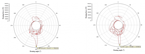
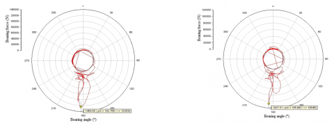
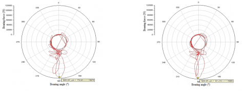
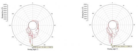
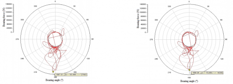
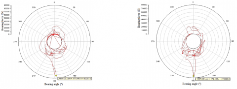
Table 2 showed the maximum bear force for each main bearing. Figure 4 showed the graph of bear forces for each main bearing under rated conditions and of Cylinder I misfired. From the table and the figure, we concluded that:
(1)The maximum bear force decreased when one cylinder misfired;
(2)As for rated conditions, the bear force of the first and second main bearing had certain difference compared with first cylinder misfire conditions; the difference percentage between rated conditions and cylinder 1 misfire conditions of bearing 1 and bearing 2 were 27.22 % and 13.82 % respectively.
(3)Single cylinder misfire had a greater influence on the loads and axis orbits of the two adjacent main bearings, but less effect on the loads and axis orbits of other main bearings.
In this paper, multi-body dynamics of a diesel engine was coupled with elastohydrodynamic lubrication of main bearings to study the lubricating properties of main bearings. The result showed that single cylinder misfire had a greater influence on the loads and axis orbits of the two adjacent main bearings, but less effect on the load and axis orbits of the other main bearings.
Table 2. Maximum bear force for each main bearing
|
Bearing number |
Rated conditions(N) |
Cylinder 1 misfire conditions(N) |
Difference percentage |
|
1 |
75223.6 |
54745.5 |
27.22% |
|
2 |
123530 |
106452 |
13.82% |
|
3 |
115976 |
115950 |
0.02% |
|
4 |
76387.8 |
75851.4 |
0.70% |
|
5 |
127803 |
116350 |
8.96% |
|
6 |
120997 |
109171 |
9.77% |
|
7 |
82207.3 |
75223.6 |
8.50% |
(a)Main bearing 1
(b)Main bearing 2
(c)Main bearing 3
(d)Main bearing 4
(e)Main bearing 5
(f)Main bearing 6
(g)Main bearing 7
Rated conditions First cylinder misfire conditions
Figure 4. Bear forces for each main bearing
1. Sarma, P.K., Krishna, D. Radha, Ramanarayanan, C.P., “Analysis of engine oil cooler of an unmanned aero- engine at various altitudes,” International Journal of Heat and Technology, 30(1): 45-50, 2012.
2. Kumar, N., Varun; Chauhan, S, “Analysis of tribological performance of biodiesel,” Proceedings of the Institution of Mechanical Engineers, Part J: Journal of Engineering Tribology, 228(7): 797-807, 2014. DOI: 10.1177/1350650114532452.
3. Loganathan, S., Anand, M., Vikraman, V., Vikas, R. “Oil pump performance optimization for three cylinder diesel engine through friction reduction,” SAE Technical Papers, 2014, SAE 2014. DOI: 10.4271/2014-01-2881.
4. Kagnici, Fatih , Akalin, Ozgen, “The effect of cylinder bore distortion on lube oil consumption and blow-by,” Journal of Tribology, 136(1), 2014. DOI: 10.1115/1.4025208.
5. Holmberg Kenneth, Andersson Peter, Nylund Nils-Olof, Erdemir Ali, “Global energy consumption due to friction in trucks and buses,” Tribology International, 78:94-114, 2014. DOI: 10.1016/j.triboint.2014.05.004.
6. C.M. Taylor, “Fluid-film lubrication in the internal combustion engine: an invited review,” International Joint Tribology Conference, 204-212, 1992.
7. Kapulainen, Markku, etc., “Fibre optic sensors for long- term monitoring of oil film pressure in diesel engine main bearing,” Tribology Letters, 2014. DOI: 10.1007/s11249-014-0373–5.
8. H.Y. Isaac Du, “Simulation of flexible rotating crankshaft engine block and hydrodynamic bearings for a V6 engine,” SAE paper, 1999-01-1752.
9. S.M. Athavale, P.R. Sajanpawar, “Analytical studies on influence of crankshaft vibrations on engine noise using integrated parametric finite element model: quick assessment tool,” SAE paper, 1999-01-1769.
10. Piancastelli, Luca, Frizziero, Leonardo, Rocchi, Ilaria, “An innovative method to speed up the finite element analysis of critical engine components,” International Journal of Heat and Technology, 30(2): 127-132, 2012.
11. Perekrestov, A.P., Chanchikov, V.A., Guzhvenko, I.N., “Modified lubricants for increasing the wear resistance of cylinder assemblies in marine diesel engines,” Russian Engineering Research, 35(3): 185-188, 2015. DOI: 10.3103/S1068798X15030144.
12. Lara, Rodolfo Francisco, etc., “Lubricant quality control: A chemometric approach to assess wear engine in heavy machines,” Tribology International, 86: 36-41, 2015. DOI: 10.1016/j.triboint.2015.01.009.
13. Lapuerta, Magín, etc., “Effect of ambient humidity and hygroscopy on the lubricity of diesel fuels,” Wear, 309(1-2): 200-207, 2014. DOI: 10.1016/j.wear.2013.11.017.
14. Lahmar M., “Comparison of the dynamic behaviour of two misaligned crankshaft bearings,” Proceeding of the Institute of Mechanical Engineers, 214(8):991-997, 2000.
15. Lahmar M., “The effect of misalignment on performance characteristics of engine main crankshaft bearings,” European Journal of Mechanics A/Solids, 21(4): 703- 704, 2002. DOI: 10.1016/S0997-7538(01)01202-5.
16. S. Boedo, J.F. Booker, “Modaland and nodal EHD analysis for gas journal bearings,” Journal of Tribology, 127(4): 306-314, 2005. DOI: 10.1115/1.1828455.
17. Sasa Bukovnik, Nicole Dorr, “Analysis of diverse simulation models for combustion engine journal bearings and the influence of oil condition,” Tribology International. 39(8): 820-826, 2006. DOI: 10.1016/j.triboint.2005.07.023.
18. Sun Jun, Wang Zhenhua, Gui Changlin, “Thermoelastohydrodynamic Elastohydrodynamic lubrication analysis of crankshaft bearing considering crankshaft deformation under load and roughness surface,” Journal of Mechanical Engineering, 45(1):135- 140, 2009. DOI: 10.3901/JME.2009.01.135.
19. Mourelatos, Z.P., “An efficient journal bearing lubrication analysis for engine crankshafts,” Tribology Transactions, 44(3): 351-358, 2001.
20. WANG Gangzhi, HAO Yanming, “Thermo elastohydrodynamic lubrication research of main bearings in IC engines,” Chinese Internal Combustion Engine Engineering, 31(5):63-68, 2010.