OPEN ACCESS
Atrium is popular element in mercantile buildings, covered shopping mall, airport terminals, and sport arenas. In the event of a fire, these buildings overwhelmingly necessitate the use of a mechanical ventilation system to provide conditions to achieve safe escape route for the building occupants. This manuscript deals with mechanical ventilation system, manual method for the hydraulic calculations and fire design scenarios. This research shows an overview of the Consolidated Model of Fire and Smoke Transport (CFAST) modeling that using to predict ventilation performance and smoke movement in an atrium. CFAST software has many uses in a wide variety of buildings and fire scenarios due to fast, reliable and affective accuracy of output data. In addition CFAST approaches provide a link between outside building weather conditions and fire and smoke development. This paper demonstrated the complete design procedure as an example to fire safety engineer.
Consolidated model, Fire and smoke transport, Mechanical ventilation system, Building atria.
Fire in an atria buildings requires more complicated operational approaches than other buildings [1] because smoking in atriums can spread to communication spaces and other occupied parts of a buildings and threat occupants and safe evacuation so that it is so difficult for fire fighters to enter the building and protect egress routes. Occupants in building have difficulties to evacuate rapidly and safely because elevators do not offer an appropriate exit during a fire expansion. Chimney effect through vertical opening such as atrium open space which allows smoke to travel through upper floors is a real threat. Considerable amount of gases toxic will produce [2] when building materials burn, which is the main cause of death.
Smoke control system means an integrated system which rises smoke in atriums continuously through floors by mechanical ventilation system [3] or by natural ventilation to extract smoke from atrium and maintain the smoke height in last floor at least 2 m above egress route [4]. Automatic sprinkler systems [5] are the most effective in controlling fires in spaces with a relatively low ceiling height. Atrium smoke management depends on the buoyancy phenomenon from rising hot smoke above a fire. As it rises, relatively cool ambient air is entrained into the fire plume and causes decrease in temperature and increase in mass flow rate of contaminated air upon reaching the ceiling.
CFAST software [6] is a two zone fire model used to calculated evolving distribution of smoke, changing in temperature degrees and fire gases throughout atrium during a fire. In addition, it is used to predict the environment building structures resulted from a fire and calculate menaces to occupant's life and building structure. The basic assumption is that all zone fire models in each atrium can be divided into a small number of control volumes that are postulated to be homogeneous within each zone; each zone is internally considered uniform in composition and temperature. In 1944, a fire in Hartford Circus [7] caused dying of 168 people. In 2006, a fire in Willow Grove Park Mall in Pennsylvania forced more than six thousand people to evacuate but no injuries were reported and shopping centre was destroyed. In 2012, 19 people were killed due to a fire in Felagio Shopping Mall in Qatar.
2.1 Design case study
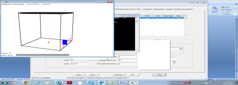
A case study is chosen as a facility with regular large atrium. The atrium which has a 20m width, 20m length and 25m height is assumed in CFAST modeling as shown in figure 1. The selected atrium consists of a horizontal flow vent (door) which locates at the half of front face with dimensions of 4 m soffit, 11 m width. The atrium’s ceiling, walls and floor are made from gypsum board (1/2 in). The fire source assumed in an atrium is sofa with simulation time of 700s.
Figure 1. Atrium geometry
2.2 Hydraulic calculations for mechanical ventilation from upper layer
To execute hydraulic calculations for mechanical ventilation [8], the physical parameters of this system are given as research project for tall atrium in open spaced buildings as shown in table 1.
Table 1. Physical parameters for mechanical ventilation
|
$\dot{Q}$ |
$\rho_{\mathrm{a}}, \rho_{\infty}$ |
$c_{p}$ |
$\mathrm{T}_{\mathrm{a}}, \mathrm{T}_{\infty}$ |
$\mathrm{g}$ |
H |
|
$539.1 \mathrm{kw}$ |
$1.2 \mathrm{kg} / \mathrm{m}^{3}$ |
$1 k j / k g$ |
$293 \mathrm{k}$ |
$9.81 \mathrm{m} / \mathrm{s}^{2}$ |
25m |
The plume mass flow rate at the interface height of 24 m can be calculated by applying the following equation [8].
$\dot{m}_{p}=0.21\left(\frac{\rho_{\mathrm{a}}^{2} \mathrm{g}}{\mathrm{C}_{\mathrm{p}} \mathrm{a}}\right)^{1 / 3} \dot{Q}^{1 / 3} \cdot Z^{5 / 3}$
Where $\dot{m}$ p is the plum mass flow rate $(k g / s)$,$\rho_{\mathrm{a}}$ is the density of ambient air $\left(k g / m^{3}\right)$,$\mathrm{g}$ is the gravity acceleration ( $9.81 \mathrm{m} / \mathrm{s}^{2}$ ), $\mathrm{C}_{\mathrm{p}}$ is the specific heat ( $k J / k g$ ), $\mathrm{T}_{\mathrm{a}}$ is the ambient temperature (K), $\dot{Q}$ is the total energy release rate ( $k \mathrm{W}$ ), $Z$ is the interface height ( $m$ ).
The area of atrium boundaries $A_{w}$ in contact with smoke layer is given as the part of walls plus the ceiling area. For sofa, $\mathrm{k}=0.00016 \mathrm{W} / \mathrm{m} . \mathrm{k}$,$\rho=700 \mathrm{kg} / \mathrm{m}^{3}$,$\mathrm{C}=1 \mathrm{kJ} / \mathrm{kg}$,$h$ is the effective heat conduction coefficient ( $k W / m^{2} \mathrm{K}$ ) as expressed in following equation:
$h=\left(\frac{\mathrm{K} \rho \mathrm{C}}{\pi \mathrm{t}}\right)^{1 / 2}$
Where k is the conductivity of the atrium surface material $(W /m . \mathrm{K})$ , $\rho$ is the density of the atrium surface material ( $k g / m^{3}$ ), $C$ is the specific heat of the atrium surface material $k J / k g . \mathrm{K}$ , t is the fire time ( $S$ ). The upper layer gas temperature can be evaluated by following equation.
$T_{\mathrm{g}}=T_{\mathrm{a}}+\frac{\dot{Q}}{\mathrm{C}_{\mathrm{p}} \dot{\mathrm{m}}+\mathrm{h} \mathrm{A}_{\mathrm{w}}}$
Where $T_{\mathrm{g}}$ is the upper layer gas temperature (K), $T_{\mathrm{a}}$ is the ambient temperature (K), $\dot{Q}$ is the total energy release rate ( $k W$ ), $\mathrm{C}_{\mathrm{p}}$ is the specific heat of plume gases, $\dot{m}{p}$ is plume mass flow rate ( $k g / s$ ), $A_{w}$ is the area of atrium boundaries in contact with smoke layer and is given as the part of walls plus the ceiling area ( $m^{2}$ ). The density of the upper layer gas shall be calculated as following equation:
$\rho_{\mathrm{g}}=\frac{353}{T_{\mathrm{g}}}$
Where $\rho_{\mathrm{g}}$ is the density of upper layer gas (kg/m3), $T_{\mathrm{g}}$ is the gas temperature (K). After numbers of iterations and repeated the previous steps, the volumetric flow rate of the fan must therefore be $104.6 \mathrm{m}^{3} / \mathrm{s}$ with area $10 m^{2}$ to achieve $\dot{m}_{\mathrm{p}}=\dot{m}_{\mathrm{e}}$ . The mass flow rate out by mechanical ventilation will be evaluated by applying following equation. $\dot{m}_{\mathrm{e}}=\dot{V} \cdot \rho_{\mathrm{g}}$
Where $\dot{m}_{p}$ is the mass flow rate by mechanical ventilation ( $k g / s$ ), $V_{e}$ is the volumetric flow of fan ( $m^{3} / s$ ), $\rho_{\mathrm{g}}$ is the density of the upper layer gas ( $k g / m^{3}$ ). The mass flow rate by mechanical
The following different operational parameters is considered in the design of mechanical ventilation system.
3.1 Geometry
Table 2.Summary of hydraulic calculation
|
$\boldsymbol{Z}$ $\boldsymbol{m}$ |
$\dot{m}_{p}$ $k g / s$ |
$\dot{m}_{e}$ $\boldsymbol{k g} / \boldsymbol{s}$ |
$\boldsymbol{T}_{\mathbf{g}}$ $\mathbf{k}$ |
$\boldsymbol{p}_{\mathbf{g}}$ $\boldsymbol{k g} / \boldsymbol{m}^{3}$ |
$\boldsymbol{A}_{\boldsymbol{w}}$ $\boldsymbol{m}^{2}$ |
$V_{e}$ $\boldsymbol{m}^{3} / \boldsymbol{s}$ |
|
24 |
124.2 |
124.16 |
297.2 |
1.18 |
480 |
104.5 |
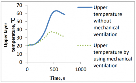
Figure (2) shows a comparison of upper layer temperature versus time in an atrium. At the beginning of fire, it is clear that the upper layer temperature is increased slightly. After 200 second, the upper layer temperature is different, the upper layer temperature is 58.5 $^{\circ} \mathrm{C}$ without using smoke control systems as shown in figure (3) but using mechanical ventilation system at flow rate 104.5 $m^{3} / s$ with area of 10 $m^{2}$ diminishes upper layer temperature to 31.2 $^{\circ} \mathrm{C}$ as shown in figure (4). On the other hand, upper layer temperature decreases because the flame height might not reach ceiling atrium and the heat transfer feedback to fuel is low. So, the fire grows due to radiation from flame to nearby objects.
Figure 2. Comparison of upper layer temperature versus time
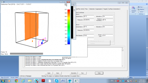
Figure 3. Upper layer temperature 58.5 ℃ without mechanical ventilation system
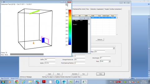
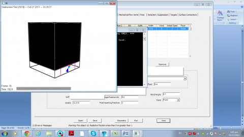
Figure 4. Upper layer temperature 31.2 ℃ using mechanical flow vent 104.5m3/s with area 10m2
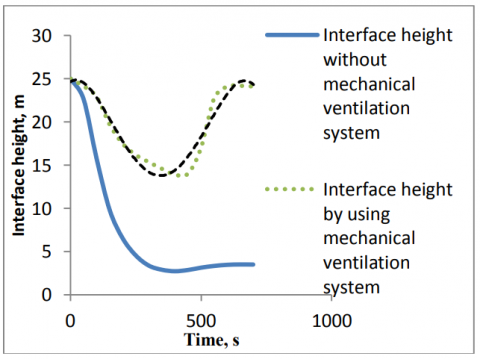
The relationship between the interface height and time is shown in figure (5), the mechanical flow vent increases smoke layer thickness and decreases interface height during first 400 second, after that, the smoke layer becomes fully of momentum storage and any mechanical external force will appear as a velocity or acceleration through vent. So, not only smoke layer thickness decreases but also interface height increases until it reaches 24m as shown in figure (6). The upper layer mechanical flow vent is frequently used to maintain a smoke level above occupants until they are able to evacuate. 3.50m The interface height is resulted, without using mechanical ventilation system as shown in figure (7).
Figure 5. Comparison of interface height versus time
Figure 6. Interface height 24m using mechanical flow vent 104.5m3/s with area 10m2
Figure 7. Interface height 3.5m without mechanical ventilation system
3.2 Door vent
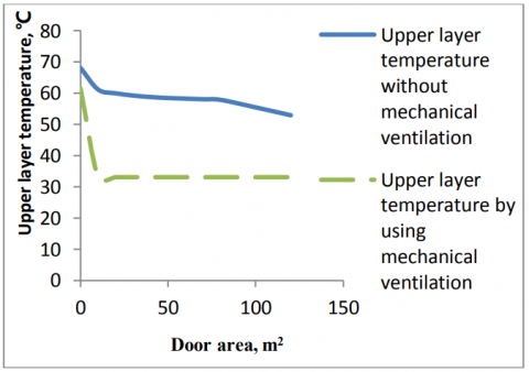
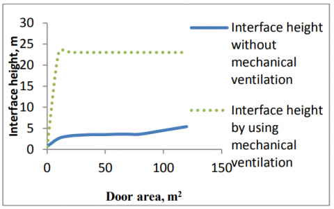
The relationship between upper layer temperature and door area is shown in figure (8), the increasing of door area reduces upper layer temperature until it seems constant due to increasing cold air that entrained to fire plume. So, the smoke layer thickness decreases and interface height increases as shown in figure (9). The pressure difference across a door vent governs flow through vent.
Figure 8. Upper layer temperature versus door area
Figure 9. Interface height versus door area
3.3 Mechanical flow rate
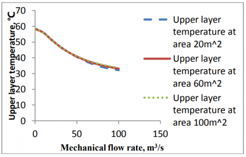
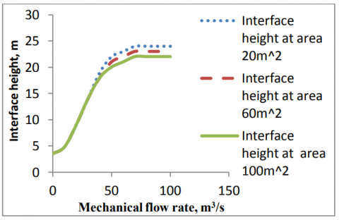
Figure (10) indicates that the upper layer temperature decreases when mechanical flow vent rate increases because mechanical ventilation forces smoke and hot gases to draw to upper atrium ceiling. As well as, this figure explains that the upper layer temperature increases with constant mechanical flow vent and increasing area of mechanical flow vent. The interface height increases when the mechanical flow vent rate increases until it reaches 24m , this height is adequate to rise smoke above occupants to ensure safe egress route as shown in figure (11). In addition, this figure indicates that the interface height decreases when area of mechanical flow vent is increased with constant mechanical flow vent.
Figure 10. Upper layer temperature versus mechanical flow rate 104.5m3/s at different area
Figure 11. Interface height versus mechanical flow rate 104.5m3/s at different area
3.4 Ambient conditions
The surrounding conditions of building should be taken into consideration. The effective of exterior ambient conditions is more than interior ambient conditions, change of interior pressure and elevation does not give notable variation in the results and so does variation in exterior elevation and relative humidity.
3.4.1 Interior temperature
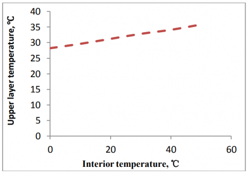
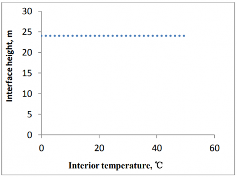
Figure (12) illustrates the relationship between interior temperature and upper layer temperature at steady exterior parameters. It observed from figure that the increasing in interior temperature causes an increase in the upper layer temperature. Moreover, figure (13) shows that the interface height is 24 m.
Figure 12. Upper layer temperature versus interior temperature
Figure 13. Interface height versus interior temperature
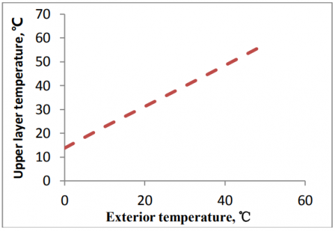
3.4.2 Exterior temperature
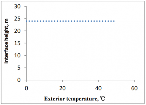
Exterior temperature plays an importance role in rising upper layer temperature at steady interior conditions in the atrium as shown in Figure (14). Figure (15) explains the relationship between interface height and exterior temperature, interface height in mechanical ventilation system is 24m.
Figure 14. Upper layer temperature versus exterior temperature
Figure 15. Interface height versus exterior temperature
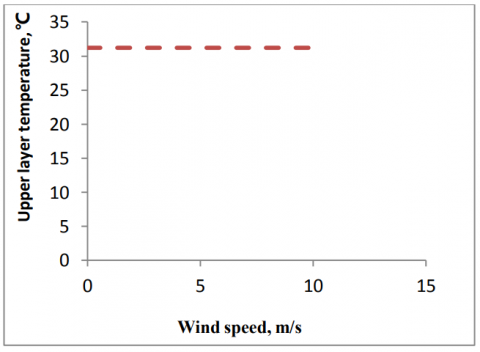
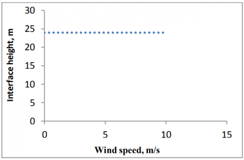
3.4.3 Wind speed
Figure (16) clarifies the relationship between upper layer temperature and wind speed, also figure (17) shows the relationship between interface height and wind speed, it is clear that this parameters seem constant in mechanical ventilation system.
Figure 16. Upper layer temperature versus wind speed
Figure 17. Interface height versus wind speed
3.4.4 Exterior pressure
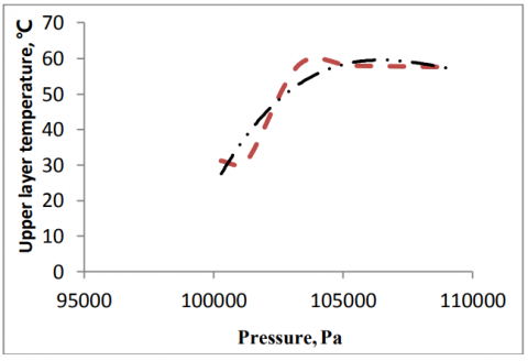
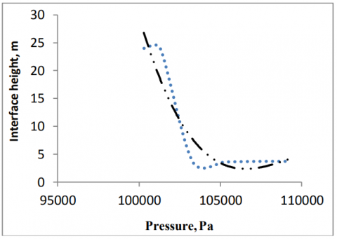
Mechanical ventilation becomes out of order if exterior pressure changes. So, the upper layer temperature increases and interface height reduces as shown in figures (18) and (19) respectively.
Figure 18. Upper layer temperature versus exterior pressure
Figure 19. Interface height versus exterior pressure
In this study a numerical simulation using CFAST for fire and smoke modeling inside atriums is laid out. The following conclusions can be summarized:
The mechanical ventilation system procedures for atrium are developed, and hydraulic calculation is applied on the selected case study. To check manual calculations, computer software (CFAST) is used.
The calculation explains effectiveness of the proposed mechanical ventilation system for atrium.
The mechanical ventilation is suitable for varied atrium heights. The increasing of flow rate of mechanical ventilation system can provide safety for occupants in atriums buildings and accomplish required interface height to maintain smoke level above the occupants in egress route to enable them to evacuate.
The simulation shows that the smoke is not hot enough to activate sprinklers system installed at the top of the atrium because the temperature of smoke decreases with elevation increase due to entrainment of cold air while the atrium sprinklers are affective in suppressing fires in ceiling with limited height. Discharge water spray from sprinklers heads cools the smoke and hot gases, and adverse effect on the occupants throughout drawing the smoke layer downward is generated via the reaction force for air drag of water droplets.
The time the smoke layer takes to descend is related to height and heat release rate of the fire source. The higher the fire source is located and the larger the heat release rate is, the more smoke causes the reduction of the time the smoke layer takes to descend.
1. Harrison R., Spearpoint, M. J., Smoke Management Issues in Buildings with Large Enclosures, Fire Australia, Melbourne, 1–3 November, 2006.
2. Malgorzata Krol, Review of Smoke Management in Atrium, Faculty of Energy and Environmental Engineering, The Silesian University of Technology, Konarskiego 20. pp. 44-100, Gliwice, Poland, 2011.
3. Lougheed, G. D., McCartney, C. and Taber, B. C., Smoke Movement for Sprinklered Fires, NRC Publications Archive, American Society of Heating Refrigerating and Air-Conditioning Engineers, ASHRAE Transactions, 106, Pt.1, pp. 605-619, Canada, 2000.
4. ASHRAE Handbook-HVAC Applications, Fire and Smoke Management, Chapter 52, Atlanta: American Society of Heating, Refrigerating and Air-Conditioning Engineers, INC, 2007.
5. Klote J. H. and Milke J. A., Principle of Smoke Management, American Society of Heating, Refrigerating and Air-Conditioning Engineers (ASHREA), INC, Atlanta, USA, 2002.
6. Peacock, R. D., Jones, W. W., Reneke, P. A. and Forney,
G. P., CFAST-Consolidated Model of Fire Growth and Smoke Transport (Version 6), Technical Reference Guide, National Institute of Standard and Technology, NIST Special Publication (1041), 2008. DOI: 10.6028/nist.sp.1026r1.
7. Jhon O. Haward, Essay in Fire Safety in Shopping Malls and Premises Liability, American Shopping Malls, 2008.
8. Bjorn Karlsson and James G. Quintiere, Enclosure Fire Dynamics, Florida, USA, 2000. DOI: 10.1201/9781420050219.