Nurlan Abduramanov | Pavel Kalashnikov | Bakhtiyar Matyakubov | Aigul Baizakova | Alikhan Kali | Tatyana Grichanaya | Yermekkul Zhaparkulova | Aigul Shaimerdenova*
© 2026 The authors. This article is published by IIETA and is licensed under the CC BY 4.0 license (http://creativecommons.org/licenses/by/4.0/).
OPEN ACCESS
Low-pressure hydrocyclones are compact pretreatment devices for drip-irrigation systems, but their hydraulic performance depends on how inlet energy and geometric parameters redistribute water between the overflow and underflow outlets. This study quantified the combined effects of inlet geometry, inlet pressure, inlet orientation, vortex-finder submersion, and underflow outlet diameter on clean-water flow distribution in an adjustable low-pressure hydrocyclone. Circular, square, and semicircular equal-area inlets were tested at inlet pressures of 9.81, 29.42, and 49.03 kPa, vertical inclinations of 0°–6°, horizontal deviations of 0°–2°, vortex-finder submersion ratios of 0, 0.77, and 1.00, and underflow outlet diameters of 9, 11, and 18 mm. Each operating condition was tested in triplicate. The overflow and underflow ratios were related to a dimensionless inlet-energy parameter and evaluated using regression and analysis of covariance. Increasing inlet energy significantly decreased Qsand/Qinputand increased Qdr/Qinput (p < 0.001), whereas the overall effect of inlet geometry was not statistically significant. Nevertheless, the semicircular inlet reached Qdr/Qinput = 0.93 at an inlet-energy value 13.7% lower than the circular inlet and 7.2% lower than the square inlet. The hydraulically preferred configuration combined a semicircular inlet, a vertical inclination of 2°–4°, a vortex-finder submersion ratio of 0.77–1.00, and a 9 mm underflow outlet. At X = 0.045, the overflow and underflow ratios were 0.976 and 0.024, respectively. These findings provide quantitative guidance for designing low-pressure hydrocyclones for drip-irrigation pretreatment. Because suspended solids were not measured, particle-removal efficiency requires separate validation under controlled suspension and field-water conditions.
drip irrigation, low-pressure hydrocyclone, flow distribution, filtration efficiency, hydraulic performance, inlet geometry, vortex-finder submersion, underflow outlet
As water resources become scarcer‚ efficient water management will be required for sustainable agricultural production in arid and semi-arid regions․ Water-saving irrigation technologies such as drip irrigation and sprinkler irrigation can reduce the amount of water used in crop production while increasing productivity or at least maintaining it [1-6]․ The long-term performance of a drip system also depends on system hydraulic reliability in addition to irrigation frequency․ Sand‚ silt‚ suspended mineral particles‚ and salts that precipitate in the narrow mazes of the emitters can compromise system discharge uniformity‚ maintenance requirements‚ and lifespan of drip lines [7-12]․ Reliable pretreatment of irrigation water is therefore important when water is supplied from wells‚ canals‚ reservoirs‚ or other sources that contain sedimentary impurities․
Hydrocyclones are used as primary pretreatment devices ahead of sand-media‚ disc‚ or screen filters. Unlike conventional settling tanks, they provide continuous operation within a compact unit and do not require replaceable filter elements. Water enters the cylindrical section tangentially, forming an outer downward vortex and an inner upward vortex. The overflow stream leaves through the vortex finder, whereas the underflow stream is discharged through the lower sand outlet. Hydrocyclone operation is therefore governed not only by pressure loss or particle-separation behavior but also by the hydraulic flow split between the two outlets. A high underflow fraction may increase water loss, while an excessively restricted underflow may adversely affect hydraulic stability and, under particle-laden conditions, limit the evacuation of accumulated solids. Consequently, the complementary ratios Qdr/Qinput and Qsand/Qinput are important hydraulic indicators for hydrocyclones intended for water-scarce irrigation systems.
Previous studies have examined hydrocyclone operation from several complementary perspectives. Analytical and probabilistic models have been developed to describe particle classification and separation behavior [13-15], while numerical and experimental studies have investigated air-core formation, fine-particle misplacement, and the effects of alternative hydrocyclone geometries [16-18]. For micro-irrigation applications, Gençoğlan et al. [19] demonstrated that inlet velocity and particle size influence separation efficiency, whereas Yurdem et al. [20] developed a dimensional model for predicting clean-water head losses in hydrocyclone filters. Field and laboratory studies have also shown that hydrocyclone pretreatment can improve the operation of downstream filtration units and irrigation distribution systems [21, 22]. Soccol and Botrel [23] compared hydrocyclones with different outlet configurations, and Mailapalli et al. [24] evaluated the effects of suspended-solid concentration and operating duration on pressure loss and particle removal. Collectively, these studies confirm that inlet velocity, pressure, particle properties, and structural dimensions all affect hydrocyclone performance.
Nevertheless, most previous investigations have focused either on particle-removal efficiency at a fixed hydrocyclone geometry, on pressure losses, or on the isolated effect of one structural parameter. Comparatively limited attention has been paid to the combined hydraulic effects of inlet cross-sectional geometry, inlet orientation in two planes, vortex-finder submersion, and underflow outlet diameter under the very-low-pressure conditions relevant to gravity-assisted and energy-constrained drip irrigation. Even when these parameters have been examined, their effects have rarely been interpreted together using complementary overflow and underflow ratios and a common dimensionless inlet-energy parameter. This limits the possibility of defining an operating window that simultaneously supports high water recovery, controlled underflow discharge, and stable flow redistribution.
Earlier studies by the authors established an adjustable low-pressure hydrocyclone platform and demonstrated that its hydraulic and separation behavior is sensitive to inlet configuration, outlet dimensions, and vortex-finder position [25, 26]. Building on this experimental platform, the present study narrows the analytical focus to the dimensionless characterization of clean-water hydraulic behavior. Clean-water testing makes it possible to isolate geometry-induced flow redistribution from the additional effects of particle concentration, density, granulometry, and interparticle interaction. The resulting hydraulic relationships are intended to provide a baseline for the subsequent evaluation of particle-laden irrigation water rather than to replace direct particle-separation testing.
The experimental factors were selected to represent distinct hydraulic design choices. The circular inlet served as the conventional reference configuration. The square inlet was included to evaluate the influence of flat boundaries and corner regions, whereas the semicircular inlet combined a flat guiding boundary with a curved outer boundary. The inlet nozzles were designed with equivalent cross-sectional areas so that the observed differences could be attributed primarily to geometry rather than to a change in flow area. Underflow outlet diameters of 9, 11, and 18 mm represented comparatively narrow, intermediate, and wide discharge conditions and enabled evaluation of the trade-off between overflow water recovery and underflow discharge. The tested inlet pressures of 0.1, 0.3, and 0.5 kgf/cm² correspond to approximately 9.8, 29.4, and 49.0 kPa, or hydraulic heads of approximately 1, 3, and 5 m, respectively. They therefore cover a very-low-pressure range relevant to gravity-fed and small-scale drip irrigation systems. Vortex-finder submersion ratios of 0, 0.77, and 1.00 represented no submersion, partial submersion, and submersion to the cylinder-cone junction.
Accordingly, this study aimed to quantify the combined effects of inlet geometry, inlet pressure, vertical and horizontal inlet orientation, vortex-finder submersion, and underflow outlet diameter on the hydraulic performance of a low-pressure hydrocyclone. The specific objectives were to:
(i) characterize the redistribution of clean-water flow between the overflow and underflow outlets;
(ii) relate the flow ratios to a dimensionless inlet kinetic-energy parameter;
(iii) identify operating conditions under which the influence of vortex-finder submersion becomes limited, and the flow curves approach a stable regime;
(iv) determine a hydraulically favorable configuration for drip-irrigation pretreatment. It was hypothesized that inlet boundary geometry and a moderate vertical inclination would influence the development of the tangential flow, while increased vortex-finder submersion and a reduced underflow diameter would shift the flow split toward the overflow stream.
The resulting framework provides quantitative design guidance for low-pressure hydrocyclones intended for drip irrigation in water-scarce regions.
2.1 Experimental design and operating conditions
A controlled laboratory experiment was conducted to determine the effects of geometric and operating parameters on pressure characteristics and water-flow redistribution in a low-pressure hydrocyclone. Clean water was used as the working liquid. The principal response variables were the flow rates and relative flow ratios at the overflow and underflow outlets.
The experimental factors summarized in Table 1 included inlet geometry, inlet pressure, inlet orientation in the vertical and horizontal planes, vortex-finder submersion, and underflow outlet diameter. Each operating condition was tested in triplicate.
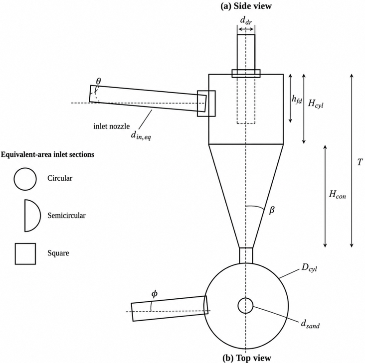
Three interchangeable inlet nozzles with circular, square, and semicircular cross-sections were examined. The circular nozzle represented the conventional reference configuration. The square nozzle was selected to evaluate the effect of flat walls and corner regions on tangential-flow development, whereas the semicircular nozzle combined a flat guiding boundary with a curved outer boundary. To isolate the effect of inlet geometry, the three nozzles had equal cross-sectional areas [26]. The common inlet area corresponded to a circular inlet diameter of 36 mm and was calculated as 1,017.9 mm². On an equal-area basis, this corresponds to a nominal square side length of 31.9 mm and a nominal semicircular diameter of 50.9 mm.
The inlet pressure was varied at three levels: 0.1, 0.3, and 0.5 kgf/cm², corresponding to 9.81, 29.42, and 49.03 kPa, respectively. These pressures are equivalent to hydraulic heads of approximately 1, 3, and 5 m and therefore represent very-low-pressure and gravity-assisted operating conditions relevant to small-scale and energy-constrained drip-irrigation systems. The pressure of 9.81 kPa was used as the lower-bound operating condition, whereas 29.42 and 49.03 kPa corresponded to the pressure heads generated by water-storage tanks elevated by approximately 3 and 5 m.
The inlet inclination in the vertical plane, denoted by θ, was set at 0°, 2°, 4°, and 6°. The inlet deviation in the horizontal plane, denoted by φ, was set at 0° and 2°. The relative vortex-finder submersion was expressed as:
$\alpha_c=\frac{h_{f d}}{H_{c y l}}$ (1)
where, hfd is the vortex-finder submersion depth, and Hcyl is the height of the cylindrical section. The tested values of αc were 0, 0.77, and 1.00, corresponding to absolute submersion depths of 0, 84.7, and 110 mm, respectively. These levels represented no submersion, partial submersion, and submersion to the cylinder-cone junction.
Three interchangeable underflow outlets with diameters of 9, 11, and 18 mm were tested. Their respective cross-sectional areas were 63.6, 95.0, and 254.5 mm². Thus, the selected diameters provided an approximately fourfold range in underflow area and represented restricted, intermediate, and comparatively wide underflow conditions. The corresponding dsand/Dcyl ratios were 0.049, 0.060, and 0.098.
Table 1. Geometric and operating parameters of the experimental hydrocyclone
|
Parameter |
Symbol |
Value or Experimental Level |
|
Cylinder diameter |
Dcyl |
184 mm |
|
Cylinder height |
Hcyl |
110 mm |
|
Cone height |
Hcon |
295 mm |
|
Total hydrocyclone height |
T = Hcyl + Hcon |
405 mm |
|
Cone half-angle |
β |
15° |
|
Full included cone angle |
2β |
30° |
|
Equivalent inlet diameter |
din,eq |
36 mm |
|
Common inlet cross-sectional area |
Ain |
1017.9 mm² |
|
Overflow pipe diameter |
ddr |
36 mm |
|
Underflow outlet diameter |
dsand |
9, 11 and 18 mm |
|
Nominal inlet pressure |
Pin |
9.81, 29.42, and 49.03 kPa |
|
Equivalent pressure head |
Hp |
1, 3, and 5 m |
|
Vertical inlet inclination |
θ |
0°, 2°, 4°, and 6° |
|
Horizontal inlet deviation |
φ |
0° and 2° |
|
Vortex-finder submersion ratio |
αc |
0, 0.77, and 1.00 |
|
Vortex-finder submersion depth |
hfd |
0, 84.7, and 110 mm |
The parameter β = 15° denotes the cone half-angle measured between the conical wall and the longitudinal axis of the hydrocyclone. The corresponding full included cone angle was therefore 30°.
2.2 Experimental hydrocyclone-pump unit
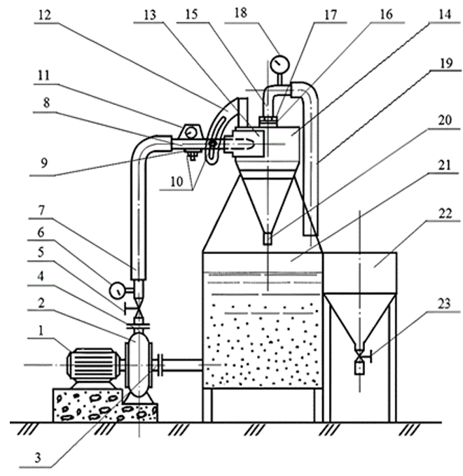
The experimental recirculation unit was assembled using a 1.5-K-6 centrifugal pump and an adjustable cylindrical-conical hydrocyclone, as shown in Figure 1.
The unit consisted of an electric motor, centrifugal pump, suction pipeline, pump discharge pipeline, regulating valve, inlet pressure gauge, flexible pressure hose, interchangeable inlet nozzle, horizontal and vertical adjustment brackets, fixing bolt, protractor, hydrocyclone chamber, adjustable overflow pipe, overflow-line pressure gauge, overflow hose, interchangeable underflow outlet, main tank, auxiliary collection tank, and drain valve.
The regulating valve installed in the pump discharge line was used to establish the prescribed inlet pressure. The inlet assembly included a flexible connection and independently adjustable vertical and horizontal brackets. This arrangement allowed the vertical inclination θ and horizontal deviation φ of the inlet nozzle to be changed without replacing the hydrocyclone body.
The overflow pipe was installed through the upper hydrocyclone cover using a threaded connection, sealing gasket, and lock nut. Its vertical position could therefore be adjusted and fixed at the prescribed submersion depth. The interchangeable underflow outlets were installed at the lower opening of the cone.
Pressure was recorded at two measurement points: immediately upstream of the hydrocyclone inlet and in the overflow line. Accordingly, the experiment measured inlet and overflow-line pressures rather than the spatial distribution of pressure inside the hydrocyclone chamber. The inlet and overflow-line pressures were recorded using hydraulic pressure gauges. Outlet-water volumes were determined using a graduated measuring vessel, the sampling duration was measured using a stopwatch, and the inlet angles were set using a protractor. The same measuring devices and collection procedure were used throughout all experimental series.
The geometric arrangement of the hydrocyclone and the positions of the adjustable structural elements are shown in Figure 2.
2.3 Experimental procedure
The main tank was filled with clean water. The pump was switched on, and the inlet pressure was adjusted using the regulating valve. The experiments were first performed at 0.1 kgf/cm² and were subsequently repeated at 0.3 and 0.5 kgf/cm².
Before each experimental series, the required inlet geometry, vertical inclination, horizontal deviation, vortex-finder submersion, and underflow outlet diameter were set. The circular, square, and semicircular nozzles were installed consecutively. The vertical inlet inclination was varied from 0° to 6°, the horizontal deviation was varied from 0° to 2°, the vortex-finder submersion ratio was varied from 0 to 1.00, and the underflow diameter was varied from 9 to 18 mm.
Water entered the cylindrical section tangentially and formed an outer downward-rotating flow and an inner upward flow. The upward stream left the hydrocyclone through the overflow pipe, whereas the lower stream left through the underflow outlet. Because clean water was used, the two outlet streams are hereafter referred to as the overflow and underflow streams.
The overflow and underflow volumes were collected simultaneously over the same time interval. During sampling, the overflow hose was redirected from the main tank to the auxiliary collection tank. At the end of the sampling interval, the hose was returned to the main tank, and the collected overflow water was transferred to a graduated measuring vessel. The underflow volume was collected separately and determined by the same volumetric method. The common collection interval was measured using a stopwatch.
The overflow flow rate was calculated as:
$Q_{d r}=\frac{w_{d r}}{t}$ (2)
where, Qdr is the overflow flow rate, L s-1; Wdr is the collected overflow volume, L; and t is the sampling interval, s.
The underflow flow rate was calculated as:
$Q_{\text {sand}}=\frac{w_{\text {sand}}}{t}$ (3)
where, Qsand is the underflow flow rate, L s-1, and Wsand is the collected underflow volume, L.
The inlet flow rate was determined from the hydraulic balance:
$Q_{\text {input}}=Q_{d r}+Q_{\text {sand}}$ (4)
The overflow and underflow flow ratios ($R_{d r}$ and $R_{\text {sand}}$) were calculated as:
$R_{d r}=\frac{Q_{d r}}{Q_{\text {input}}}$ (5)
$R_{\text {sand}}=\frac{Q_{\text {sand}}}{Q_{\text {input}}}$ (6)
Because the two outlet streams constituted the total inlet flow:
$R_{d r}+R_{\text {sand}}=1$ (7)
The overflow ratio Rdr represented the proportion of inlet water discharged through the overflow pipe, whereas the underflow ratio Rsand represented the proportion discharged through the lower outlet. The ratios were used as complementary indicators of hydraulic flow redistribution.
The pressure difference between the inlet and overflow line was determined as:
$\Delta P=P_{i n}-P_{d r}$ (8)
where, Pin is the measured inlet pressure and Pdr is the pressure measured in the overflow line.
2.4 Dimensionless hydraulic analysis
The inlet velocity was calculated from the total inlet flow rate and the common inlet cross-sectional area:
$V_{\text {input}}=\frac{Q_{\text {input}}}{A_{\text {in}}}$ (9)
where, Vinput is the mean inlet velocity, m s-1, and Ain = 1.0179 × 10⁻³ m².
The measured inlet pressure was converted to an equivalent pressure head:
$H_{\text {input}}=\frac{P_{\text {in}}}{p_\omega g}$ (10)
where, Hinput is the inlet pressure head, m; $p_\omega$ is the density of water, kg m-3; and g = 9.81 m s-2. For the three tested pressures, Hinput was approximately 1, 3, and 5 m.
A dimensionless inlet-energy parameter was calculated as:
$X=\frac{V_{\text {input}}^2}{g\left(H_{\text {input}}+T\right)}$ (11)
where, T = 0.405 m is the total internal height of the hydrocyclone. The use of pressure head in Eq. (10) ensured dimensional consistency.
The hydraulic relationships were expressed as:
$R_{\text {sand}}=f(X)$ (12)
$R_{d r}=f(X)$ (13)
The inverse relationship proposed for the underflow ratio was evaluated as an empirical regression model:
$R_{\text {sand}}=\frac{N}{X}$ (14)
where, N is a fitted, configuration-dependent coefficient. The coefficient was estimated separately for the tested inlet geometries rather than being treated as a universal hydrocyclone constant. Its experimentally observed order of magnitude was approximately 10-3.
2.5 Statistical and regression analysis
Each operating condition was tested three times, and the arithmetic mean of the three measurements was used to calculate the hydraulic response variables and construct the flow-ratio curves. Because Rdr and Rsand are complementary variables, Rdr was used as the principal response variable in inferential comparisons, while Rsand was retained for engineering interpretation of underflow discharge.
The effects of inlet geometry were evaluated using analysis of covariance, with inlet geometry as the categorical factor and the dimensionless inlet-energy parameter X as the continuous covariate. Comparisons among the three underflow outlet diameters and among the vortex-finder submersion levels were performed using one-way analysis of variance for operating conditions with equivalent pressure and inlet orientation. Tukey’s honestly significant difference test was used for pairwise post-hoc comparisons. Statistical significance was accepted at p < 0.05.
The inverse model for Rsand and the nonlinear response curves for Rdr were fitted by least-squares regression. Model performance was evaluated using the coefficient of determination (R2), adjusted R2, root mean square error (RMSE), and mean absolute error (MAE). Model residual standard deviation and bootstrap 95% confidence intervals based on 10,000 resamples were used to characterize uncertainty in the fitted relationships.
Common-X comparisons and the X values corresponding to specified overflow ratios were estimated using shape-preserving piecewise cubic Hermite interpolation (PCHIP), which preserves the monotonicity of the experimental response curves.
The approximate transition to a stable hydraulic regime was evaluated using segmented regression. The breakpoint and its 95% confidence interval were estimated separately for the inlet geometries, thereby avoiding selection of the convergence threshold solely through visual inspection of the curves.
Statistical calculations and regression fitting were performed in Python 3.13.5 using SciPy 1.17.0 and statsmodels 0.14.6.
3.1 Underflow flow distribution
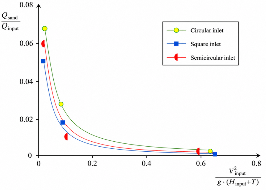
Figure 3 shows the relationship between the underflow flow ratio Rsand and the dimensionless inlet-energy parameter X for circular, square, and semicircular inlet geometries at a vertical inlet inclination of θ = 2°. The numerical values underlying the curves are presented in Table 2.
Figure 3. Relationship between the underflow flow ratio and the dimensionless inlet-energy parameter for circular, square, and semicircular inlet geometries at θ = 2°
Table 2. Underflow flow ratios for the tested inlet geometries
|
X |
Circular Inlet, Rsand |
Semicircular Inlet, Rsand |
Square Inlet, Rsand |
|
0.0209 |
0.0533 |
0.0379 |
0.0470 |
|
0.0568 |
0.0396 |
0.0304 |
0.0277 |
|
0.6437 |
0.00256 |
0.00215 |
0.00130 |
An increase in X produced a pronounced and monotonic reduction in the proportion of water discharged through the underflow outlet. Between the lowest and highest evaluated values of X, Rsanddecreased by 95.2% for the circular inlet, 94.3% for the semicircular inlet, and 97.2% for the square inlet. Thus, dimensionless inlet energy was the principal factor controlling hydraulic flow redistribution.
The relative performance of the inlet geometries depended on the operating range. At X = 0.0209, the semicircular inlet produced the lowest underflow ratio. At X = 0.0568, however, the semicircular inlet produced an Rsandvalue 30.1% lower than that of the circular inlet and 8.8% lower than that of the square inlet. At X = 0.6437, the underflow ratio for the semicircular inlet was 49.1% lower than that for the circular inlet and 39.7% lower than that for the square inlet. The hydraulic advantage of the semicircular configuration was therefore most evident under moderate and high inlet-energy conditions.
The absolute difference between the highest and lowest underflow ratios among the three inlet geometries decreased from 0.0153 at X = 0.0209 to 0.00126 at X = 0.6437, corresponding to a 91.8% reduction in between-geometry spread. This convergence indicates the development of a high-energy operating region in which the underflow ratio becomes only weakly dependent on inlet shape.
The curves obtained at different vortex-finder submersion levels also approached one another as X increased. Approximate flow-convergence thresholds were observed at X ≥ 0.025 for the semicircular inlet and X ≥ 0.030 for the square inlet. These values are interpreted as empirical operational thresholds rather than universal self-similarity criteria because they were identified from convergence within the investigated geometric and pressure ranges.
Model-based ANCOVA of the plotted response values confirmed the dominant effect. The fitted power exponent was -0.968, with a 95% confidence interval from -1.201 to -0.735. Because the theoretical inverse exponent of −1 was contained within this interval, an inverse approximation was considered acceptable for engineering interpretation. The model explained 95.9% of the log-transformed response variation, with an adjusted R2 of 0.934.
The influence of X was statistically significant, F(1, 5) = 114.49, p < 0.001, whereas the overall inlet-geometry effect was not significant, F(2, 5) = 0.76, p = 0.514. The model residual standard deviation was 0.390 log units, while the RMSE and MAE on the original response scale were 0.0107 and 0.0079, respectively. These results indicate that inlet geometry affected the rate of transition toward the low-underflow regime but did not override the dominant effect of inlet energy.
Fitting the inverse approximation described in Materials and Methods produced N values of 1.252 × 10⁻³, 0.907 × 10⁻³, and 1.055 × 10⁻³ for the circular, square, and semicircular inlet geometries, respectively. The common fitted coefficient was 1.071 × 10⁻³. Allowing separate coefficients for the three geometries did not significantly improve the fit, F(2, 6) = 0.68, p = 0.540. Therefore, N should be regarded as an empirical coefficient with an order of magnitude of 10-3, rather than as a universal physical constant.
3.2 Overflow flow distribution
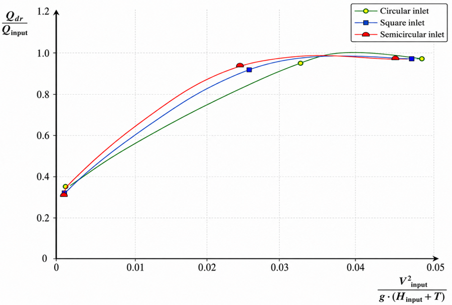
Figure 4 shows the relationship between the overflow flow ratio Rdr and X for circular, square, and semicircular inlet geometries. The detailed comparison was conducted at θ = 2°, Dcyl = 184 mm, Hcyl = 110 mm, ddr = 36 mm, dsand = 9 mm, and β = 15°. The numerical values retained in the original experimental table are presented in Table 3.
Figure 4. Relationship between the overflow flow ratio and the dimensionless inlet-energy parameter for circular, square, and semicircular inlet geometries at θ = 2° and dsand = 9 mm
Table 3. Overflow flow ratios for the tested inlet geometries
|
Inlet Geometry |
Initial Condition |
Intermediate Condition |
Highest Evaluated Condition |
Underflow Ratio at the Highest Condition |
|
Circular |
X = 0.001; Rdr = 0.347 |
X = 0.032; Rdr = 0.958 |
X = 0.048; Rdr = 0.978 |
0.022 |
|
Square |
X = 0.001; Rdr = 0.314 |
X = 0.026; Rdr = 0.934 |
X = 0.047; Rdr= 0.979 |
0.021 |
|
Semicircular |
X = 0.001; Rdr = 0.323 |
X = 0.024; Rdr = 0.933 |
X = 0.045; Rdr =0 .976 |
0.024 |
At X = 0.001, the overflow ratio ranged from 0.314 to 0.347. An increase in X caused a rapid rise in the overflow fraction, which approached 0.98 for all three inlet geometries. From the lowest to the highest evaluated operating conditions, the complementary underflow fraction decreased by 96.6% for the circular inlet, 96.9% for the square inlet, and 96.5% for the semicircular inlet.
At the highest evaluated conditions, the overflow ratios were 0.978, 0.979, and 0.976 for the circular, square, and semicircular inlets, respectively. The total difference among the three terminal values was only 0.003. By comparison, the corresponding spread at X = 0.001 was 0.033. Thus, the between-geometry variation decreased by approximately 90.9% as the hydrocyclone approached the high-overflow operating region.
The semicircular inlet did not produce a higher terminal overflow ratio than the other geometries. Its practical advantage was the earlier attainment of the high-overflow regime. The semicircular inlet reached Rdr= 0.933 at X = 0.024, whereas the square inlet reached a similar value of 0.934 at X = 0.026, and the circular inlet reached 0.958 at X = 0.032.
A comparison at the common value X = 0.024, obtained by shape-preserving PCHIP of the retained points, gave estimated overflow ratios of 0.896 for the circular inlet, 0.922 for the square inlet, and 0.933 for the semicircular inlet. Relative to the conventional circular inlet, the semicircular configuration therefore increased the overflow fraction by 3.7 percentage points at the same dimensionless inlet-energy condition. The corresponding advantage over the square inlet was 1.1 percentage points.
The estimated X values required to attain Rdr = 0.90 were 0.0243 for the circular inlet, 0.0220 for the square inlet, and 0.0203 for the semicircular inlet. The estimated X values required to attain Rdr= 0.93 were 0.0271, 0.0252, and 0.0234, respectively. Thus, the semicircular inlet attained an overflow ratio of 0.93 at an X value approximately 13.7% lower than the circular inlet and 7.2% lower than the square inlet; the model-based statistical assessment of the hydraulic response curves is presented in Table 4.
Table 4. Model-based statistical assessment of the hydraulic response curves
|
Response Dataset |
Power Exponent and 95% CI |
Adjusted R2 |
Model Residual SD, Log Units |
RMSE |
Effect of X |
Effect of Inlet Geometry |
|
Underflow ratio, Figure 3 |
-0.968 [-1.201; |
0.934 |
0.390 |
0.0107 |
F(1, 5) = 114.49, p < 0.001 |
F(2, 5) = 0.76, p = 0.514 |
|
Overflow ratio, Figure 4 |
-0.838 [-0.980; |
0.966 |
0.280 |
0.0210 |
F(1, 5) = 232.80, p < 0.001 |
F(2, 5) = 0.11, p = 0.897 |
The power-model exponent for the complementary underflow fraction was -0.838, with a 95% confidence interval from -0.980 to -0.697. The model explained 97.9% of the log-transformed response variation and had an adjusted R2 of 0.966. On the original overflow-ratio scale, the RMSE was 0.0210 and the MAE was 0.0156. The model residual standard deviation was 0.280 log units.
Dimensionless inlet energy had a statistically significant effect, F(1, 5) = 232.80, p < 0.001, whereas the overall inlet-geometry term was not significant, F(2, 5) = 0.11, p = 0.897. Consequently, the preferred inlet geometry should not be selected only from the maximum observed overflow ratio. A more informative engineering criterion is the dimensionless inlet energy required to reach a specified overflow ratio. According to this criterion, the semicircular inlet provided the earliest transition toward the high-water-recovery regime.
3.3 Effects of inlet orientation and vortex-finder submersion
Across the complete experimental matrix, an increase in vortex-finder submersion generally shifted the hydraulic flow split toward the overflow outlet. This effect was most pronounced at vertical inlet inclinations of 2°–4°. The operating combinations associated with overflow ratios of approximately 0.90-0.98 are summarized in Table 5.
At θ = 0°, changes in φ and αc had only a limited influence once X approached approximately 0.036. At θ = 2°–4°, increasing the vortex-finder submersion from αc = 0.77 to 1.00 produced the most consistent shift toward the overflow stream.
At θ = 6° and αc = 0, the lowest overflow response occurred at φ = 0°. Increasing the horizontal deviation to φ = 2° increased the overflow fraction, indicating that the effect of horizontal orientation became relevant under the unfavorable combination of a large vertical inclination and no vortex-finder submersion. Over the experimental matrix as a whole, however, the effect of changing φ from 0° to 2° was smaller than the effects of X, θ, and αc.
For the square inlet at θ = 4°, the response curves showed a smaller spread than those obtained with the circular inlet, indicating reduced sensitivity to changes in φ and αc. A similar tendency remained at θ = 6°, although it was less pronounced.
Table 5. Operating combinations associated with high overflow ratios
|
Vertical Inlet Inclination, θ |
Approximate X |
Horizontal Deviation, φ |
Vortex-Finder Submersion Ratio, αc |
|
0° |
0.040 |
0°–2° |
0–1.00 |
|
2° |
0.040 |
0°–2° |
0.77–1.00 |
|
4° |
0.035 |
0°–2° |
1.00 |
|
6° |
0.043 |
0°–2° |
0–1.00 |
For the semicircular inlet at θ = 2°, high overflow ratios were attained over the broadest combination of the investigated geometric settings. At θ = 4°, the same tendency was observed mainly within the X range of approximately 0.030–0.040. These findings support the use of a moderate vertical inclination rather than either a completely horizontal inlet or the maximum tested inclination.
3.4 Hydraulically preferred configuration
Among the underflow outlet diameters of 9, 11, and 18 mm, the 9 mm outlet produced the most favorable hydraulic water-recovery condition and was therefore retained for the detailed comparison in Figure 4. Reducing the underflow diameter restricts the quantity of water discharged from the lower outlet and shifts a greater proportion of the inlet flow toward the overflow pipe.
The combined results identified a semicircular inlet, a vertical inclination of 2°–4°, a vortex-finder submersion ratio of 0.77–1.00, and a 9 mm underflow outlet as the preferred hydraulic configuration. At the highest evaluated condition for the semicircular inlet in Figure 4, X = 0.045, the overflow and underflow ratios were 0.976 and 0.024, respectively.
Accordingly, 97.6% of the inlet water was recovered through the overflow outlet, while 2.4% was discharged through the underflow outlet. This configuration should be interpreted as hydraulically favorable in terms of flow distribution and water recovery. The measured ratios do not, by themselves, represent suspended-particle removal efficiency.
4.1 Influence of inlet energy on hydraulic performance
The principal finding of the study was that hydraulic flow redistribution depended predominantly on the dimensionless inlet-energy parameter. In both datasets, the statistical effect of X was highly significant, whereas the overall effect of inlet geometry was not. Inlet geometry therefore influenced the location and rate of transition toward the high-overflow regime, but sufficiently high inlet energy caused all three configurations to converge toward similar terminal flow ratios.
This behavior is physically consistent with the development of rotational flow inside a hydrocyclone. Increasing inlet velocity raises tangential momentum and strengthens the outer rotating stream. The more organized vortex directs a larger proportion of the liquid toward the internal upward flow and overflow pipe, while the relative underflow fraction decreases. The progressive convergence of the three inlet geometries indicates that, after a sufficiently strong vortex has formed, the influence of the initial nozzle boundary shape becomes secondary.
Gençoğlan et al. [19] similarly found that water velocity was a major determinant of hydrocyclone performance in micro-irrigation pretreatment. Average separation efficiency increased from 71% at 1.0 m s-1 to 84% at 1.5 m s-1 and 90% at 2.0 m s-1. Their reported average efficiencies for three hydrocyclone geometries were 69%, 88%, and 88%, indicating that the effects of operating velocity could be as important as, or greater than, differences among structural configurations. These findings are consistent with the present model-based result showing a significant X effect but a nonsignificant overall inlet-geometry effect.
The nearly inverse exponent obtained for the broad-range underflow response provides a quantitative explanation for the asymptotic form of Figure 3. However, the fitted coefficient N should be applied only within the tested pressure and geometric ranges. Its magnitude may change with hydrocyclone diameter, cone angle, vortex-finder diameter, underflow diameter, surface roughness, or the presence of an air core. The fitted coefficient is therefore an engineering correlation rather than a universal hydrocyclone constant.
4.2 Mechanistic interpretation of inlet geometry
The semicircular inlet did not provide a statistically higher terminal overflow ratio. Instead, it reduced the value of X required to reach the high-overflow region. This distinction is important because it identifies the principal benefit of the geometry as a reduction in the hydraulic input required to establish a favorable flow split.
The observed behavior may be attributed to the combination of a flat guiding boundary and a curved outer boundary. The flat section can direct the incoming stream tangentially along the hydrocyclone wall, while the curved section avoids the two pronounced corner regions present in a square inlet. This configuration may reduce local flow separation and produce a more coherent peripheral vortex.
The square inlet also reached the high-overflow region earlier than the circular reference inlet. However, its corner regions may create localized recirculation zones and nonuniform velocity gradients. The circular inlet avoids corners but lacks the flat guiding surface of the semicircular inlet. These competing effects explain why differences were apparent during vortex development but became small after the flow approached its terminal hydraulic regime.
The proposed explanation is based on the measured outlet-flow response. Internal tangential velocity, turbulence intensity, air-core dimensions, and recirculation zones were not directly visualized. Consequently, the mechanism should be confirmed in future studies using particle-image velocimetry or validated computational fluid dynamics.
4.3 Effects of inlet inclination and vortex-finder submersion
A moderate vertical inclination of 2°–4° produced the most favorable hydraulic response. A small downward component of inlet momentum can support the external descending vortex and promote rapid development of rotational flow. At θ = 0°, this downward component is absent. At θ = 6°, the stronger axial component may increase asymmetry and mixing between the outer descending and inner ascending streams. Therefore, the optimal condition was not the greatest tested inclination but an intermediate range that supported vortex development without excessive axial disturbance.
The comparatively weak influence of changing the horizontal deviation from 0° to 2° indicates that small departures from the nominal tangential direction do not substantially alter the hydraulic flow split under most operating conditions. The stronger response observed at θ = 6°, αc = 0, and φ = 2° suggests an interaction among the orientation parameters rather than a uniform independent effect of horizontal deviation.
Increasing vortex-finder submersion shifted the flow toward the overflow outlet, particularly at θ = 2°–4°. A deeper vortex finder places the overflow entrance farther from the inlet disturbance and can reduce direct short-circuit flow between the inlet and overflow opening. It may also improve the organization of the internal ascending stream and reduce the sensitivity of the flow split to small variations in inlet orientation.
The present hydraulic optimum is consistent with previously published two-phase testing of an adjustable hydrocyclone, in which the greatest clarification was reported for a semicircular inlet, a vertical inclination of 2°–4°, and vortex-finder submersion to the cylinder-cone junction [26]. That earlier particle-laden experiment provides supporting evidence for the practical relevance of the configuration identified by the current clean-water hydraulic analysis; it is not presented here as a new result of the present experiment.
The recommended submersion ratio of 0.77–1.00 remains specific to the tested cylinder height, cone geometry, and overflow diameter. Excessive vortex-finder insertion in a different hydrocyclone may increase hydraulic resistance or alter the air-core structure. Therefore, the geometric ratios should be preserved when the design is transferred to another unit.
4.4 Influence of the underflow outlet diameter
The underflow outlet controls the balance between water recovery and the discharge capacity of the lower stream. The cross-sectional areas of the 9, 11, and 18 mm outlets were 63.6, 95.0, and 254.5 mm², respectively. Thus, reducing the diameter from 18 to 9 mm decreased the outlet area by 75%, producing a strong hydraulic restriction and increasing the fraction of water recovered through the overflow pipe.
The 9 mm outlet was hydraulically favorable because it produced the lowest water discharge through the underflow. Nevertheless, the smallest outlet is not necessarily optimal under all particle-laden conditions. A restricted underflow opening may increase the probability of blockage, solids accumulation within the cone, or transition from spray discharge to an unstable rope-like discharge when the water contains high concentrations of coarse particles.
Accordingly, the 9 mm outlet is recommended for low-pressure operation where high-water recovery is a priority and the sediment load is moderate. The 11 or 18 mm outlets may be more appropriate when the source water contains a high coarse-sediment concentration and greater solids-discharge capacity is required. This trade-off should be evaluated using controlled suspensions before selecting the outlet diameter for a particular water source.
4.5 Relationship between hydraulic flow distribution and particle separation
The present response variables characterize hydraulic flow distribution rather than filtration efficiency. A high overflow ratio means that a large proportion of the inlet water is recovered through the upper outlet; it does not necessarily mean that the overflow contains a lower concentration of suspended solids.
Particle separation also depends on particle diameter, density, shape, inlet concentration, residence time, turbulence, and the mass distribution of solids between the overflow and underflow streams. Gençoğlan et al. [19] reported average separation efficiencies ranging from 78% for 0.5 mm sand to 84% for 2.5 mm sand. This demonstrates that the same hydraulic configuration may have different performance for different particle-size fractions.
Mailapalli et al. [24] also showed that hydrocyclone performance changed with the concentration of suspended solids and operating duration. Their experiments included initial clean-water testing followed by testing at suspended-solid concentrations of 300, 600, 900, and 1200 mg L-1. The resulting variation in pressure loss and removal efficiency confirms that clean-water hydraulic behavior is an essential baseline but cannot replace particle-specific validation.
The hydraulically preferred configuration identified in the present study should therefore be considered the starting operating window for subsequent solid-phase testing. Direct validation should include turbidity, total suspended solids, particle-size distribution, solids recovery through the underflow, mass-balance closure, and long-term emitter-clogging performance.
The absence of particle measurements also means that the comparison between the conventional circular inlet and the semicircular inlet represents a hydraulic before-and-after comparison. At the common value X = 0.024, the semicircular inlet increased the overflow ratio from an estimated 0.896 to 0.933. This improvement demonstrates more favorable water redistribution but should not be described as a measured reduction in particle concentration or turbidity.
4.6 Practical applicability and scalability
The tested pressures of 9.81–49.03 kPa correspond to hydraulic heads of approximately 1–5 m. The two upper pressure levels are consistent with gravity-assisted drip-irrigation systems supplied from storage tanks installed approximately 3–5 m above the irrigated area. This operating range is relevant to small farms, remote fields, and water-scarce regions where high-pressure pumping is technically or economically undesirable.
At the selected underflow ratio of 0.024, every 1000 m³ of water passing through the hydrocyclone would produce approximately 976 m³ of overflow and 24 m³ of underflow. This does not necessarily represent an irreversible loss. The underflow stream may be discharged into a sedimentation chamber, after which the clarified supernatant can be returned to the source tank. Such recirculation would preserve the solids-discharge function while reducing net water loss.
Table 6. Scenario-based seasonal underflow volumes at Rsand = 0.024
|
Crop or Application |
Reported Irrigation Requirement, m³ ha-1 |
Calculated Underflow Volume, m³ ha-1 |
|
Apple orchad |
718–961 |
17.2–23.1 |
|
Soybeans |
3900 |
93.6 |
|
Grain corn |
4450 |
106.8 |
|
Vegetables |
5450 |
130.8 |
|
Sugar beet |
5500 |
132.0 |
The practical scale of the underflow volume can be illustrated using published irrigation requirements for southern Kazakhstan. Reported drip-irrigation norms are 3900 m³ ha-1 for soybeans, 4450 m³ ha-1 for grain corn, 5450 m³ ha-1 for vegetables, and 5500 m³ ha-1 for sugar beet [27]. Drip-irrigated apple orchards have reported seasonal irrigation rates of 718–961 m³ ha-1 [28] with the corresponding scenario-based seasonal underflow volumes summarized in Table 6.
These calculations illustrate the importance of underflow collection and recirculation in water-scarce regions. Even a relatively small underflow ratio may correspond to a considerable seasonal volume when the hydrocyclone serves a large irrigated area.
For large-scale systems, several hydrocyclones of the tested geometry should preferably be installed in parallel. Parallel installation maintains the validated geometric ratios, permits individual units to be isolated for inspection, and allows treatment capacity to be adjusted according to irrigation demand. Direct proportional enlargement of the hydrocyclone body without further testing could alter the vortex structure and should therefore be avoided.
The design is also suitable for modular retrofitting. The inlet nozzle, underflow outlet, and vortex-finder position can be changed without replacing the entire hydrocyclone body. The main potential economic benefits are lower required operating pressure, reduced loading of downstream disc or media filters, reduced cleaning frequency, and recovery of most of the treated water through the overflow outlet.
A complete cost-benefit assessment would require local values for fabrication, pump efficiency, measured pressure loss, electricity price, annual operating time, maintenance labor, downstream-filter replacement, and the economic value of recovered water. Therefore, the present analysis establishes technical feasibility and the principal cost drivers but does not claim a measured payback period.
Crop and soil type do not directly change hydrocyclone hydrodynamics. They influence the required system flow rate, seasonal operating duration, and downstream irrigation demand. Water-source properties-including suspended-solid concentration, particle-size distribution, particle density, organic matter, algae, and mineral precipitation-are more directly relevant to hydrocyclone selection and maintenance.
4.7 Limitations and directions for further research
The current experiments quantified clean-water flow redistribution. Turbidity reduction, total suspended solids, particle-size separation, cut size, solids recovery, and long-term emitter clogging were not directly measured. The proposed configuration is therefore hydraulically preferred but requires particle-laden validation before it can be described as optimal in terms of filtration efficiency.
The model-based statistical assessment showed that dimensionless inlet energy had a strong and significant effect, whereas the overall inlet-geometry term was not significant. The recommendation of the semicircular inlet is consequently based on its earlier transition into the high-overflow region, its lower underflow fraction at moderate and high X, and its agreement with previously published particle-laden testing, rather than on a statistically higher terminal overflow ratio.
The empirical convergence values of approximately 0.025 for the semicircular inlet and 0.030 for the square inlet should not be regarded as universal self-similarity thresholds. Their applicability is restricted to the hydrocyclone dimensions, pressure range, outlet diameters, and inlet orientations used in this study. Future replicated experiments should estimate these breakpoints together with confidence intervals.
Pressure was measured upstream of the hydrocyclone and in the overflow line. Consequently, the experimental setup did not determine the spatial location of the maximum pressure inside the chamber. The relationships between internal pressure distribution, air-core position, tangential velocity, and hydraulic stability should be investigated using additional pressure taps, flow-visualization methods, or computational fluid dynamics.
Further work should compare the circular baseline configuration and the hydraulically preferred semicircular configuration under identical pressure, flow, and particle-loading conditions. The recommended validation matrix should include the three underflow diameters, controlled particle-size fractions, several suspended-solid concentrations, and at least three independent replicates per condition. This would allow hydraulic water recovery, particle-removal efficiency, pressure loss, blockage risk, and operating cost to be optimized simultaneously.
The hydraulic performance of the low-pressure hydrocyclone was governed primarily by the dimensionless inlet-energy parameter. Increasing this parameter consistently reduced the underflow ratio and increased the overflow ratio, while differences among the circular, square, and semicircular inlet geometries became progressively smaller at higher inlet-energy conditions. The main advantage of the semicircular inlet was therefore not a higher terminal overflow ratio, but an earlier transition to the high-overflow operating regime.
The hydraulically preferred configuration comprised a semicircular inlet, a vertical inclination of 2°–4°, a vortex-finder submersion ratio of 0.77–1.00, and a 9 mm underflow outlet. At X = 0.045, this configuration produced an overflow ratio of Qdr/Qinput = 0.976 and an underflow ratio of Qsand/Qinput = 0.024. Small changes in the horizontal inlet deviation from 0° to 2° had a comparatively limited effect under most operating conditions.
These findings provide quantitative guidance for adjusting low-pressure hydrocyclones used as pretreatment units in drip-irrigation systems. However, the experiments characterized clean-water flow redistribution and did not directly measure turbidity, suspended-solids removal, particle-size separation, or emitter-clogging reduction. Therefore, the proposed configuration should be considered hydraulically favorable, while its particle-removal efficiency requires confirmation through controlled suspension and field-water experiments.
This work is the result of collaboration among the authors; however, N.A. and P.K. contributed to all sections of the study. B.M. contributed to methodology, analysis, interpretation of results, and original project preparation. A.B. contributed to methodology and case-study analysis. A.K. contributed to methodology and interpretation of results. T.G. was responsible for writing and language editing. Y.Z. contributed to data curation, validation, and visualization. A.S. was responsible for supervision, project administration, manuscript coordination, and review and editing of the final version.
This research was funded by the Ministry of Water Resources and Irrigation of the Republic of Kazakhstan (Grant No.: BR23791322).
We thank the Ministry of Water Resources and Irrigation of the Republic of Kazakhstan for the technical support provided during various analyses conducted as part of this scientific research.
[1] Angold, Ye.V., Zharkov, V.A. (2014). Special features of drip sprinkler irrigation technology. Water Supply, 14(5): 841-849. https://doi.org/10.2166/ws.2014.041
[2] Angold, Ye.V., Zharkov, V.A., Kalashnikov, A.A., Balgabayev, N.N. (2016). Features of impulse sprinkling technology. Water Supply, 16(5): 1178-1184. https://doi.org/10.2166/ws.2016.037
[3] Matyakubov, B., Nurov, D., Radjabova, M., Fozilov, S. (2022). Application of drip irrigation technology for growing cotton in Bukhara region. AIP Conference Proceedings, 2432: 040014. https://doi.org/10.1063/5.0091186
[4] Burkhonova, M., Narzullayev, J., Matyakubov, B., Isayev, S. (2024). Study on the application of sprinkler irrigation technology for the growth of carrots and cauliflowers. E3S Web of Conferences, 563: 03077. https://doi.org/10.1051/e3sconf/202456303077
[5] Burkhonova, M., Matyakubov, B., Nazaraliev, D., Mamataliev, A., Botirov, S. (2024). Study on the significance of irrigation technology for carrot growth. E3S Web of Conferences, 563: 03064. https://doi.org/10.1051/e3sconf/202456303064
[6] Matyakubov, B., Nurov, D., Kodirov, Z., Shodmonova, M. (2025). Effect of drip irrigation technology on cotton productivity. AIP Conference Proceedings, 3256(1): 020044. https://doi.org/10.1063/5.0267188
[7] Feng, D., Kang, Y.H., Wan, S.Q., Liu, S.P. (2017). Lateral flushing regime for managing emitter clogging under drip irrigation with saline groundwater. Irrigation Science, 35(3): 217-225. https://doi.org/10.1007/s00271-017-0536-x
[8] Adin, A., Sacks, M. (1991). Dripper clogging factors in wastewater irrigation. Journal of Irrigation and Drainage Engineering, 117(6): 813-826. https://doi.org/10.1061/(ASCE)0733-9437(1991)117:6(813)
[9] Nakayama, F.S., Boman, B.J., Pitts, D.J. (2007). 11. Maintenance. Developments in Agricultural Engineering, 13: 389-430. https://doi.org/10.1016/S0167-4137(07)80014-X
[10] Ahmadaali, K.A,, Liaghat, A., Dehghanisanij, H. (2009). The effect of acidification and magnetic field on emitter clogging under salt water application. Journal of Agricultural Science, 1(1): 132-141. https://doi.org/10.5539/jas.v1n1p132
[11] Zhou, B., Li, Y.K., Liu, Y.Z., Xu, F.P., Pei, Y.T., Wang, Z.H. (2015). Effect of drip irrigation frequency on emitter clogging using reclaimed water. Irrigation Science, 33(3): 221-234. https://doi.org/10.1007/s00271-015-0461-9
[12] Zhou, B., Li, Y.K., Song, P., Zhou, Y.P., Yu, Y., Bralts, V. (2017). Anti-clogging evaluation for drip irrigation emitters using reclaimed water. Irrigation Science, 35(3): 181-192. https://doi.org/10.1007/s00271-016-0530-8
[13] Sabbagh, R., Koch, C.R., Lipsett, M.G., Nobes, D.S. (2017). Hydrocyclone equivalent settling area factor at higher concentrations and developing a performance chart. Separation and Purification Technology, 182: 171-184. https://doi.org/10.1016/j.seppur.2017.02.054
[14] Krokhina, A.V., Lvov, V.A., Pavlikhin, G.P. (2017). A probabilistic-statistical model of the particle classification process in small hydrocyclone classifiers. Chemical Engineering and Technology, 40(5): 967-972. https://doi.org/10.1002/ceat.201600602
[15] Grechushkin, A.N., Lvov, V.A. (2019). A probabilistic-statistical model of change of particle size distribution in settlers and tanks. Chemical Engineering and Technology, 42(4): 812-817. https://doi.org/10.1002/ceat.201800571
[16] Xu, Y.X., Song, X.F., Sun, Z., Tang, B., Yu, J.G. (2016). Steady-state distribution of air-core in a hydrocyclone. The Canadian Journal of Chemical Engineering, 95(4): 757-766. https://doi.org/10.1002/cjce.22720
[17] Banerjee, C., Dubey, R.K., Majumder, A.K. (2017). Phenomenological study on fine particle misplacement behavior in a hydrocyclone. Transactions of the Indian Institute of Metals, 70(2): 313-322. https://doi.org/10.1007/s12666-016-0993-6
[18] Vakamalla, T.R., Koruprolu, V.B.B., Arugonda, R., Mangadoddy, N. (2017). Development of novel hydrocyclone designs for improved fines classification using multiphase CFD model. Separation and Purification Technology, 175: 481-497. https://doi.org/10.1016/j.seppur.2016.10.026
[19] Gençoğlan, C., Şahan, H., Gençoğlan, S. (2023). Determination of separation efficiency of hydrocyclone used pre-filter in micro irrigation at different inlet velocities and sand diameters. Journal of Agricultural Science, 29(1): 60-67. https://doi.org/10.15832/ankutbd.983589
[20] Yurdem, H., Demir, V., Degirmencioglu, A. (2010). Development of a mathematical model to predict clean water head losses in hydrocyclone filters in drip irrigation systems using dimensional analysis. Biosystems Engineering, 105(4): 495-506. https://doi.org/10.1016/j.biosystemseng.2010.02.001
[21] Lamskova, M.I., Novikov, A.E., Borodychev, S.V., Filimonov, M.I. (2021). Evaluation of corn crops drip irrigation quality at different versions of the tillering zone. IOP Conference Series: Earth and Environmental Science, 843: 012060. https://doi.org/10.1088/1755-1315/843/1/012060
[22] Ovchinnikov, A.S., Denisova, M.A., Pustovalov, E.V., Bocharnikov, V.S., Bocharnikova, O.V., Kozinskaya, O.V. (2022). Modernization of structural elements of a hydrocyclone to improve the efficiency of irrigation water treatment. IOP Conference Series: Earth and Environmental Science, 965: 012017. https://doi.org/10.1088/1755-1315/965/1/012017
[23] Soccol, O.J., Botrel, T.A. (2004). Hydrocyclone for prefiltering of irrigation water. Scientia Agricola, 61(2): 134-140. https://doi.org/10.1590/S0103-90162004000200002
[24] Mailapalli, D.R., Marques, P.A.A., Thomas, K.J. (2007). Performance evaluation of hydrocyclone filter for microirrigation. Engenharia Agrícola, 27(2): 373-382. https://doi.org/10.1590/S0100-69162007000300006
[25] Kalashnikov, A., Abduramanov, N., Kalashnikov, P., Bayzakova, A., Rysmahanov, N. (2020). Optimization of low-pressure hydrocyclone sizes for drip irrigation system. Journal of Advanced Research in Dynamical and Control Systems, 12(5): 191-198. https://doi.org/10.5373/JARDCS/V12SP5/20201748
[26] Kalashnikov, A.A., Abduramanov, N.A., Kalashnikov, P.A., Baizakova, A.E., Denisyuk, N.V. (2023). Regulation of hydrocyclone parameters to improve the quality of water purification in drip irrigation systems. Caspian Journal of Environmental Sciences, 21(4): 787-799. https://doi.org/10.22124/cjes.2023.7129
[27] Gritsenko, N., Kalashnikov, P., Mirdadayev, M., et al. (2026). Optimal use of irrigated lands through water-saving technologies and development of water supply systems in agriculture. World Journal of Environmental Biosciences, 15(1): 37-46. https://doi.org/10.51847/aEwA7LOKEu
[28] Zharkov, V.A., Zhaparkulova, E.D., Mirdadayev, M., Shaimerdenova, A., Beisenkulova, A.B., Kalashnikov, P.A. (2026). Irrigation methods influence on water productivity, and fruit yield and quality of apple cultivar golden delicious. SABRAO Journal of Breeding and Genetics, 58(3): 1345-1355. https://doi.org/10.54910/sabrao2026.58.3.37