Atheer Saleem Almawla* | Ammar Hatem Kamel | Assim Mohammed Lateef
© 2021 IIETA. This article is published by IIETA and is licensed under the CC BY 4.0 license (http://creativecommons.org/licenses/by/4.0/).
OPEN ACCESS
Spillways are designing to release surplus water over a volume of storage. The excess water flows from the top of the reservoir and is carried back to the river by a spillway. Many radial gates were destroyed under hydrodynamic load. Radial gate connectors are susceptible to fatigue failure due to excessive vibration; therefore, gate vibration during operation must be investigated to confirm safe operation at the design water pressure. Several studies were carried out to analyse and simulation of flow over the spillway. In this article, the flow pattern over the Haditha dam spillway has been simulated using computational fluid dynamics (CFD). The numerical model was performed using Ansys Fluent 2020 R1 to simulate the flow properties; determination of cavitation damage at three discharges corresponding in the design of Haditha dam are 4700, 7140, and 7900 m3/s. In addition to finding the effect of gate vibration under dynamic water loads. The Realisable k-ɛ turbulence model was utilised with the volume of fluid (VOF) model to simulate the interaction between air and water phases. The validation of the numerical model was achieved by comparing it with a physical model. The physical model of the Haditha Dam spillway was made from iron with a scale of 1:110. It has been designed and constructed in a hydraulic laboratory according to the modelling principle of the hydraulic structure. The results showed that a high agreement between the physical and numerical model and the k-ɛ turbulence model could simulate the Haditha dam spillway with low cost and few times. The cavitation damage may occur at the region start at the end of the arching spillway to stretches downstream, and there is no damage of gate vibration under dynamic water load.
Ansys fluent, CFD numerical model, cavitation, k-ɛ turbulence model, physical model, VOF model, vibration
A spillway is one of the most important hydraulic that represents a safety valve of a Dam [1]. It works on the excess passing water downstream. The design of the spillway must be sufficient to release the floodwaters more than the reservoir capacity. The appropriate design of spillway prevents the potential risk of failure and dam overtopping. A spillway is very important to the safety of dams. Because of high flow over the spillway, the design must be pretty complicated and faces high flow kinetic energy and cavitation problems. A spillway may be designed within the dam's body or alongside the dam, or quite away from it depends on many considers, but it can be best built independently of the dam [2].
The spillway can be classified into many different forms: according to purpose as an emergency and auxiliary spillway; according to flow as a controlled (gated) spillway and uncontrolled spillway; according to hydraulic criteria as ogee, chute, side channel, tunnel and siphon spillways. The type is selected and designed according to many considers such as topography, hydrology, geology, the purpose of the project, and the economics of the project [3].
A discharge coefficient (C) is a quantitative variable that measures the spillway's efficiency at moving floodwaters [4]. This vital design parameter represents the losses in approach channels. The losses include transition losses, entrance loss, and losses caused by the curvature of the upstream channel; these losses must be added to the total head for determining the elevations of the reservoir [5]. In crests- gated spillway, the discharge at a partial opening may be computed as similar to flow through a low head Orifice by using the following equation [6].
Q = Cg. D. L. $(2 g H)^{1 / 2}$ (1)
where,
Cg = discharge gated coefficient;
D = gate opening in meter;
L = net length of the spillway crest;
g = gravity acceleration;
H = vertical distance between the total upstream head and the centre of the gate opening.
In recent years, due to the great climatic changes and the dams built on the Euphrates River basin, a significant fluctuation in the quantities of water entering Iraq occurs. For example, in 2019, the rainfall rates on the river basin increased significantly from their normal rates during the winter season, as the quantities of water exceeded the levels of natural storage. The water rose to reach the levels of the design discharge of the spillways for most dams in Iraq. It is caused to the emergence of some problems related to the operation and design of these dams and spillways. Then the water levels decreased, and the water quantities dramatically reduced in the summer season and the subsequent two seasons in 2020 and 2021, which forces the authorities responsible for managing water resources to reconsider the management plans of this system. To study and address these problems and increase the operational efficiency of the water resources system in Iraq, several scenarios must be examined and tested to assess this efficiency, especially about the associated hydraulic structures, such as dams and spillways.
Physical models were used for many years to simulate the complex flow over the spillway. A physical model is time consuming and causes high design costs. There are other limitations of physical models, such as the effect of scaling, where they may be unable to capture behaviour such as cavitation and tension of surface readily. Applying different scenarios in the physical model is difficult or impossible and difficult to visualise or understand turbulent flows [7-9]. The behaviour of flow over spillways can be studied in a short time and without paying high expenses by using the numerical model [10, 11]. Moreover, the flow process can better show using the numerical model with the equation and appropriate coefficient under analytical solution at different scenarios.
Computational fluid dynamics (CFD) has been used to simulate flow over the spillway. It is a branch of fluid mechanics that solves flow problems using numerical methods [12]. The results have been compared and evaluated against a physical model. Many water resource engineers have attempted to study flow over spillways with different mathematical models and computational techniques. Alhashimi [13] used Fluent software to simulate flow over ogee spillway and compared the results with experimental data. She used the volume of fluid (VOF) model to obtain the free surface in each case. She takes a spillway of Mandali Dam as a case study to calibrate her numerical models. Her study results indicate that in the case the RNG k-ɛ turbulent model is used, the accuracy of the results obtained from the flow over ogee spillway has been increased.
A numerical study on stepped and ogee spills with finite volumes and finite elements was conducted by Daneshfaraz et al. [14]. In that study, Fluent and ADINA software and experimental data was compared using two discretization methods in numeric solution. They Found a good agreement between experimental and numerical results. Meanwhile, fluent software results were more accurate than ADINA Software's finite element.
Kumcu [15] comparing experimental data and CFD analysis for flow over the spillway for under construction Kavsak Dam in Turkey. She investigated experimentally by a physical model using a 1/50 scale to conducting experiments, and Flow depth, discharge, pressure data were recorded for different flow conditions. She used discharge rating curves, velocity patterns, and pressures to compare the physical model results and the numerical model. Her study shows that there is reasonably good agreement between the physical and numerical models in flow characteristics.
Comparison of physical modelling and CFD simulation of flow over the spillway in the Arkun Dam was studied by Ucar and Kumcu [16], they comparing the hydraulic characteristics between software (CFD) and 1/60-scaled physical model using Flow-3D by the finite-volume method to solve the Navier- Stokes equation (RANS). Their study proved the good conformity of numerical models with the physical model in flow characteristics.
ANSYS Fluent software has been used by Barzegari et al. [17] to simulate the flow over Aydoghmush Dam (Iran) spillway. They constructed a physical model from Plexiglas at a scale of 1:40 at the Water Research Center in Iran. The authors used three different discharges (35, 800, 1850) m3/s to calculate flow parameters and determine the cavitation index. They applied the volume of fluid (VOF) model to assess the profile of free surface flow and the stander κ–ε model as a turbulent model. The researchers found an excellent acceptance between a result of Fluent and physical model. Also, they proved that the cavitation did not occur in their case study at any of the flow rates.
A flow simulation on the Ogee spillway was carried out by Damarnegara et al. [18] using the OpenFOAM open-source CFD platform. The flow is simulated using the VOF approach to resolve the dynamics of free a surface. In comparison with experimental measures and the USBR calculation method, they concluded that the results show a good harmony on the spillway rating curve and no significant influence on the outage rating curve was demonstrated in the mesh configuration. In addition, they recommend that the numerical simulation is sufficiently accurate to be used as a design tool in the design iteration process before testing design, which can be saved time and money.
Several studies were carried out to verify numerical results using physical models for different spillway types by using Flow 3D software [19-26]. All of them found a good agreement between a result of the numerical and physical model.
The present study seeks to confirm that a numerical model can model the flow pattern over the Haditha Dam spillway by using Ansys Fluent software, check the cavitation damage and determine the effect of radial gate vibration under dynamic water load.
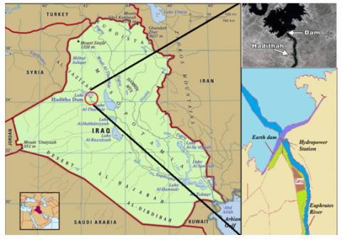
Haditha Dam is an earthfall Dam located at 34◦120 latitudes and 42◦210 longitudes on the narrow stretch of the Euphrates River, about 8 km northwest of Haditha city, which Located about 270 km northwest of Baghdad. Haditha Dam was constructed for multi-functional purposes and is used for hydroelectricity generation, regulating the flow of the Euphrates River and irrigation of field water (see Figure 1). After the Mosul Dam, the Haditha Dam is considered the second largest electrical supplier of power [27].
Figure 1. Map of location and layout of Haditha dam on the Euphrates River [27]
The total length of the Haditha dam is around 9 km, and the maximum height is 57 m high from the deepest point of the river. The total Dam storage is 6 trillion cubic meters at a normal operating level. and the maximum water storage capacity of about 8.3 trillion cubic meters [28]. The hydraulic investigation of spillway layouts was started in April 1976. The spillway is a controlled type with six radial gates divided by piers (5.0 m and 7.0 m thick) (see Figure 2).
Figure 2. Sketch of Haditha Dam spillway with radial gate
The surface spillway profile represents a horizontal sill (134.0 m high (a.s.l.) and 26.5 m long), which conjugates over a 60 m radius curve with an inclined end section (inclination angle 20°). The discharge via turbines and discharge via spillway during a flood is shown in Table 1. At a normal water level equal to 143 m flow rate would amount to 4700 m3 / s [29]. The maximum discharge recorded over spillway through six gates was 7900 m3 / s (Management of Haditha Dam project, Unpublished data).
Table 1. Discharge via turbines and spillway during flood passage
|
Probability % |
Total discharge m3/s |
Discharge via station m3/s |
Discharge via spillway m3/s |
|
0.01 |
12500 |
1500 |
11000 |
|
1 |
5200 |
1900 |
3300 |
The fundamental physical principles equation of fluid dynamics is considered as a governing equation of CFD. Mass conservation, momentum and energy show the conservation form of the partial differential governing equations. In a fluid dynamic state, the continuity equation is the mass rate that enters a system compared to the mass rate that leaves the system and the mass accumulation in the system. Although a fluid element's shape and volume change as it moves, its mass remains constant because its mass changes at a constant rate (conserved mass) as it moves along the flow. The conservation equation or continuity equation is considered as below [30].
$\frac{\partial \rho}{\partial t}+\nabla \cdot(\rho \vec{v})=0$ (2)
where,
ρ is fluid density (kg/ m3);
t is the time (s);
$\vec{v}$ is a vector of velocity (m/s).
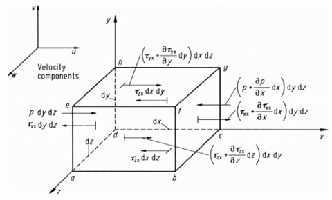
The second governing equation is a momentum equation. The momentum equation expresses Newton's second law; it involves relating the sum of the forces acting on a fluid element to its acceleration [31]. Newton's second law is the resulting force that acts on the body and can be written as the rate of change of momentum of a body. It occurs in the direction of force, which is divided into two groups: surface and body force. These forces act directly on the fluid element's volumetric mass (see Figure 3).
Figure 3. Infinitely small, moving fluid element
The general Navier-Stokes governing equations can be shown as Eq. (3).
$\frac{\partial}{\partial t}(\rho \vec{V})+\nabla \cdot(\rho \vec{V} \vec{V})=-\nabla p+\nabla \cdot(\tau)+\rho \vec{f}$ (3)
The fluid can be taken as a Newtonian fluid for a hydrodynamic problem. Stokes in 1845 obtained the following equation for Newtonian fluids,
$\tau=\lambda \nabla \cdot \vec{V}+2 \mu \frac{\partial u}{\partial x}$ (4)
where: (μ) is a viscosity coefficient and (λ) is a bulk viscosity coefficient.
The third governing equation is a conservation of energy (the first law of thermodynamics), which can be demonstrated as below:
$\frac{\partial \rho e}{\partial t}+\vec{\nabla} .(\rho e \vec{v})=\rho \dot{q}+\vec{\nabla} .(k \vec{\nabla} T)-\vec{\nabla} .(\rho \vec{v})+\vec{\nabla} .(\vec{\tau} . \vec{v})+\rho \vec{b} . \vec{v}$ (5)
where,
q̇ = rate of volumetric heat addition per unit mass
T = temperature
e = internal energy per unit mass.
4.1 Physical model setup
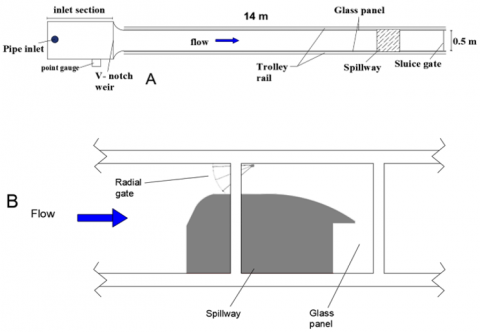
The physical model tests for this study were carried out in the Hydraulic Laboratory of the University of Anbar, located in the Anbar governorate. The physical model was constructed to simulate of flow pattern over the Haditha Dam spillway. The spillway of Haditha Dam consists of six spaces with six radial gates. The piers between the spaces of spillway are 5 and 7 m in width alternately. The model was constructed inside an open channel at a hydraulic laboratory to simulate only two spaces of the Haditha Dam spillway. The current study included two spaces of the spillway because it was very difficult to simulate all spillway and very high cost. The length of the open channel is 17 m with 50 * 50 cm cross section area enclosed by glass. Figure 4, illustrates the top and side view of the open channel and model.
Figure 4. Layout of the experimental setup A) Plan view, B) side view
The physical model was made from iron with a scale of 1:110. It was designed and constructed in accordance with the principles of hydraulic modelling and similarity. The scale has been chosen after optimising many scales to achieve the best scale that can be represented inside the laboratory open channel and overcome the viscous and surface tension forces represented by Reynolds number and Weber number [32].
Table 2 represents the relationship between the Haditha Dam spillway (prototype) and physical model on the Froude similarity using a scale of 1: 110.
Table 2. The scale factor of the Haditha dam spillway
|
Parameter Scale value |
Law of scale |
value |
|
Length |
$L_{r}$ |
110 |
|
Velocity |
$V_{r}=L_{r}^{0.5}$ |
10.5 |
|
Discharge |
$Q_{r}=L_{r}^{2.5}$ |
126905.87 |
|
Time |
$T_{r}=L_{r}^{0.5}$ |
10.5 |
|
Force |
$F_{r}=L_{r}^{3}$ |
1331000 |
|
Pressure |
$P_{r}=L_{r}$ |
110 |
After setting up of physical model, three different discharges were taken to the simulation of a prototype. These discharges are (4700, 7142 and 7900) m3/s representing discharge at normal water level, Design discharge of spillway at Probability 0.1% and maximum discharge recorded over spillway through operation, respectively (Management of Haditha Dam project, Unpublished data (.
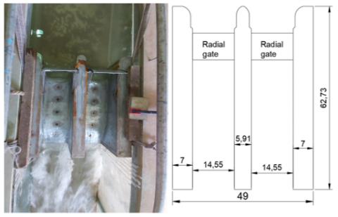
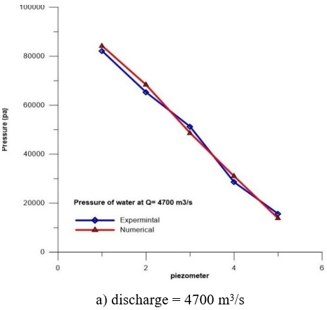
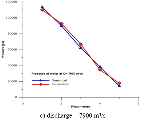
To measure pressure over the surface spillway, the ten piezometers were fixed (five piezometers for each span) with 9 cm space between each piezometer and another Figure 5 and 6.
The depth of water above the spillway was measured by point gauge to determine free surface water, and the depth of water downstream was measured too.
Figure 5. Physical model of Hadith dam
Figure 6. Top view of the physical model
4.2 Numerical model setup
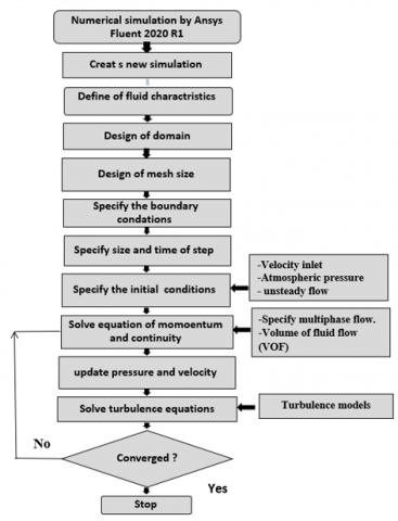
The numerical model can be used to study the flow over spillways in a short amount of time and without incurring high costs. A numerical model can predict fluid dynamic forces, mass flow rate, heat transfer rate, and pressure drop. The Ansys Fluent numerical software 2020 R1 has been used in this study to simulate of flow pattern over Haditha Dam spillway. Ansys Fluent is a powerful numerical modelling software capable of solving a wide range of fluid flow problems. Ansys Fluent software uses the finite volume method (FVM) to solve the continuity and unsteady 3D RANS equations. In the present study, the Realisable (k–ε) model was used in Fluent software due to more harmonious flow on surfaces with big curves [33]. The k-ε model is one of the most effective closure turbulence models frequently used in CFD modeling [34-37]. The volume of fluid (VOF) model has been selected to simulate multiphase flow. The air and water are defined in two phases: primary and secondary, respectively. The flowchart below summarises the steps of simulation on the numerical model Figure 7.
Figure 7. The steps of simulation on the numerical model
4.2.1 Construction of geometry
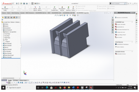
The Ansys fluent software supports the format files stereolithography (STL). This format file is popular in some of the used software such as CAD software which includes AutoCAD, Free Cad, 3D Max, SolidWorks, Sketch-Up, etc. The STL file is usually used for 3D printing; it is more exact than other files. The 3D geometry of Haditha Dam spillway and domain of flow over spillway has been constructed by using Solidwork software 2019 Figure 8. After that, the geometry was saved as Parasolid (x,t) file format and imported into Ansys fluent.
4.2.2 Mesh generation:
A meshing or grid generation is the second essential stage of preprocessing after geometry construction. The meshing process is a significant step in CFD modelling and requires considerable attention. In order to analyse the fluid flow, the domain must be subdivided into smaller cells. Essentially, the accuracy of a CFD solution depends upon the number of cells in the mesh. The finer mesh, the better precision of the solution [38].
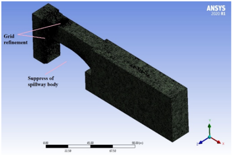
There are many options in the two-dimensional meshing process, such as triangular and quadrilateral meshing. Still, in a 3D model, the mesh may consist of either a tetrahedron or a quadrilateral mesh or several various combinations [39]. In the present study the symmetry and refinement were applied on the domain of the spillway to reduce the number of elements; thus, reducing the time of ran. Figure 9 depicts the three-dimensional model meshing for the Haditha Dam spillway.
Figure 8. Design of 3D geometry by using Solidwork software
Figure 9. Three-dimensional model meshing for Haditha Dam spillway
The mesh quality assessment and mesh sensitivity function has been established after the correct mesh type was achieved for each model. The mesh quality plays a significant role in the accuracy and stability of numerical computation. As documented in ANSYS Fluent User's Guide (2013) [40], the list of quality criteria for mesh metric includes element quality, aspect ratio, Jacobean ratio, warping factor, parallel deviation, maximum corner angle, skewness, and orthogonal quality, which corresponded in the present study.
4.2.3 Boundary conditions
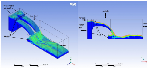
The precision of boundary conditions plays a vital role in the results of domain simulation. The boundary conditions are flow input and output boundaries that need to be defined with the flow characteristics such as turbulence parameters, velocity, and pressure. The internal faces and walls which have direct interaction with the flow were also represented. In this article, the inlet boundary is located upstream of the inlet water at the bottom and the air inlet at the top. A velocity inlet boundary was chosen as the best option for the inlet water, resulting in a stable flow in the solution domain. The input velocity was calculated and uniformly set at the inlet for each discharge tested in physical modelling. The air boundaries were defined in the atmosphere as an outlet pressure. On the other hand, at the downstream part, the outlet of the domain has been specified with an outlet pressure so that water and air can flow out freely (see Figure 10).
Figure 10. Model boundary condition in two and three dimensions
5.1 Analysis, results, and discussions of flow over spillway
The numerical model becomes indispensable for design a huge hydraulic structure such as dam. The validation of any numerical model must be check before adopting. The validation of the numerical model usually is achieved by comparing a result of the numerical model with field results or physical model. In this article, the physical model has been constructed by using 1/ 110 scale. Three different discharges are used to simulation of flow patterns over the Haditha Dam spillway. These discharges are 4700 m3/s, 7140 m3/s, and 7900 m3/s.
Figure 11. The pressure over the surface of the spillway
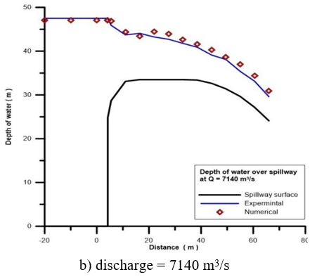
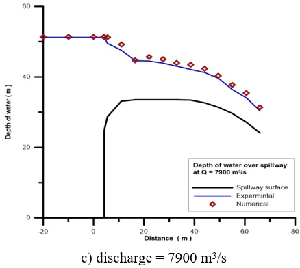
Figure 12. Depth of water over the spillway
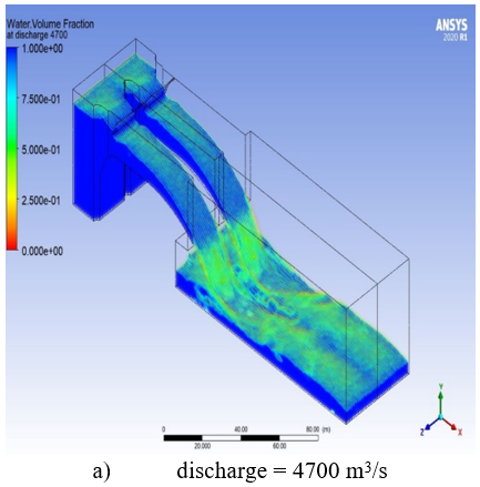
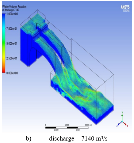
The volume of fluid (VOF) model has been used in the present numerical model to track the interface between phases of water and air. VOF tracks the fluid mass movements and determines the volume fraction of each mesh cell. The fraction of phase can be taken any value from 0 to 1 [41].
Five piezometers were fixed over the surface of the spillway to measure pressure and to compare it with CFD numerical model. As shown in Figure 11, the results illustrate a good agreement between physical and numerical models.
Another indicator or parameter used to check the model validation is water depth or water elevation over the spillway measured to find the free surface flow. Figure 12 shows the relation between distances and depth of water at three discharges. Results show a high accuracy numerical simulation of flow patterns with experimental results, which mean the numerical model is valid to simulate the flow patterns over the Haditha Dam spillway.
Figure 13 shows a simulated region of fractional water and air phase and water surface. The behaviour of water in the numerical model (volume of water fraction) is very much like the physical model.
Figure 13. Phases of water and air in simulated case
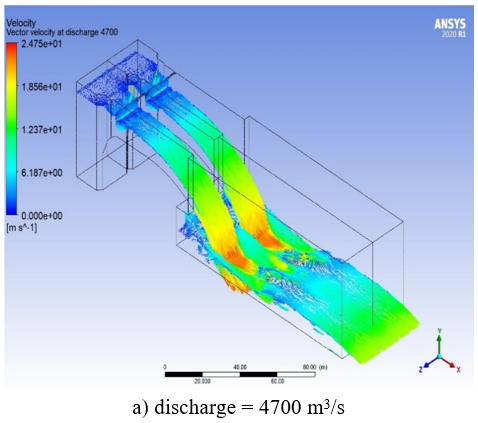
The flow vectors over the spillway are shown in Figure 14 at three different discharges. This figure shows evident velocity vector changes from straight to curvature, where flow passes under the gate.
Figure 14. Velocity vectors
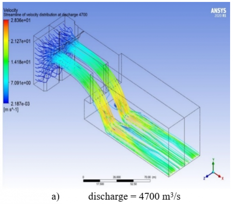
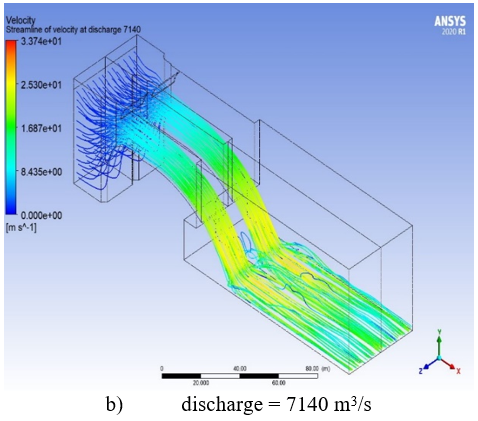
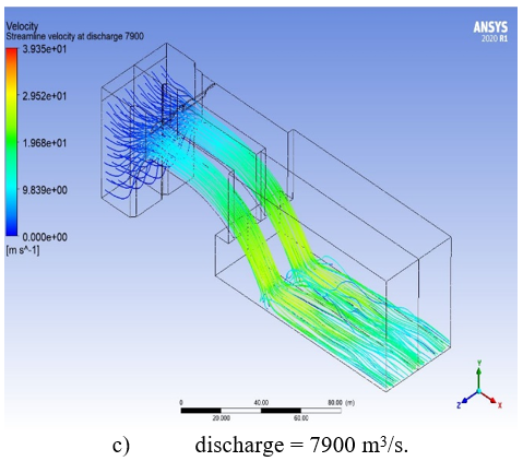
To further examine the numerical models' predictive abilities to simulate the flow over the spillway, streamlines of flow at three different discharges were simulated as shown in Figure 15. The figure shows the velocity streamlines become highly over the curvature of the spillway that is logical behaviour and agrees with general theories and measurements.
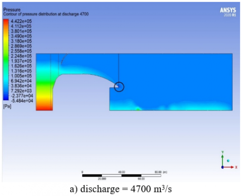
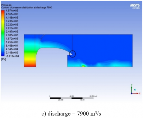
The pressure distribution over the entire domain and in the proximity of the surface spillway illustrate as a contour line in Figure 16.
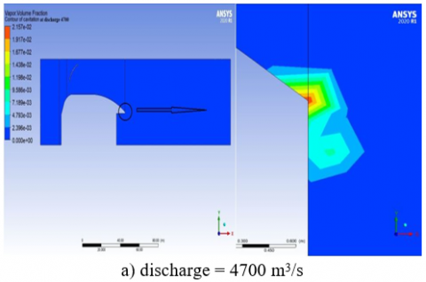
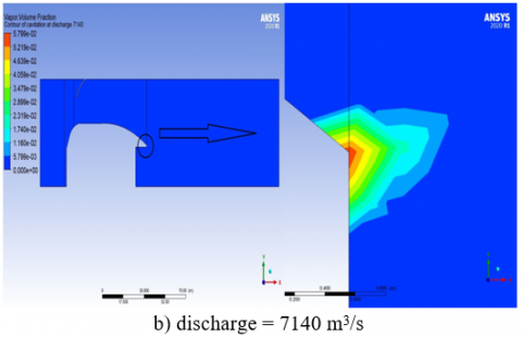
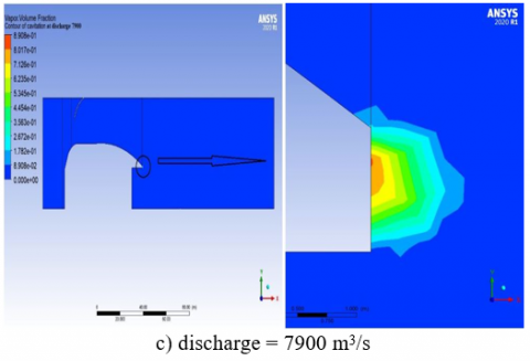
In Figure 16, the negative pressure is seen over the crest in the region starts at the end of the arching spillway to stretches along with downstream, and it may be caused cavitation damage. Cavitation is the formation of vapour cavities in a liquid that occurs when the flow velocity is high [36]. Cavitation damage can be increase with cracks, surface roughness, ramp and offset [29].
Figure 15. Velocity streamlines
Figure 16. The contour line of pressure distribution
Figure 17. Contour line of cavitation distribution
The cavitation can be modelled in Ansys Fluent using three phases (air, water liquid, and water vapour). Figure 17 shows the contour line of the zone at cavitation damage.
5.2 Analysis, results, and discussions of vibration effect
Extreme vibration can be led to fatigue failure in the radial gate connectors; thus, vibration for the gate during operation must be investigated to confirm safe operation to design water pressure. Because of eddy generated by the fluctuation of the water pressure during flow, significant vibrations could be produced. It is caused by the split and reattachment of the flow of water around the radial gate and by the resulting unstable flow under the gate [42, 43]. Radial gates of the Japanese Wachi Dam and the US Folsom Dam were destroyed due to vortex-induced vibrations generated by the partially opened gates in 1967 and 1995, respectively [44].
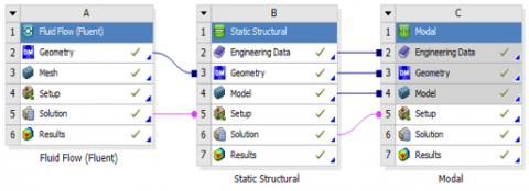
The evaluation of the mode shape of the Haditha Dam spillway radial gate has been checked by using Ansys Workbench. After simulation of the numerical model using Fluent, the analysis system (static structural) was used to determine the total deformation on the gate. It is attached to the solution of Fluent and to find the vibration mode Ansys system (mode) connected on the solution of static structural as shown in Figure 18.
The vibration damage under the radial gate of the spillway has been checked in at worst case. The worst case was at design discharge of Haditha Dam spillway (11000 m3/s) with gate opening ten meters simulated to determine eight mode shapes. Figures 20 and 21 illustrate the first to eight mode shapes of the Haditha dam's gated spillway.
The natural frequency of the radial gate has been calculated according to the dimensions and properties of the gate (see table 3) by using MATLAB for equation (6) below. According to Eq. (6) and data in Table 3, the natural frequency value is (21.4275 Hz).
Table 3. Dimensions and material design propertise of the radial gate of Haditha dam spillway
|
Dimension |
Value |
|
Width of gate |
16 m |
|
High of gate |
13.5 m |
|
Thickness of gate |
25.2 cm |
|
Radius |
16.6 m |
|
Material property |
Value |
|
Density |
7850 $\mathrm{kg} / \mathrm{m}^{3}$ |
|
Unit weight |
78.5 $\mathrm{kN} / \mathrm{m}^{3}$ |
|
Modulus of elasticity |
210000 Mpa |
|
Shear modulus G |
81000 Mpa |
|
Poisons ratio in the elastic range |
0.3 |
|
Coefficient of linear thermal expansion |
12 * $10^{-6} K^{-1}$ |
Figure 18. The connection between the ANSYS-Fluent system, the Static-Structural and modal setup
The pressure imported on the gate shows in Figure 19.
Figure 19. The imported pressure on radial gate
$\omega_{N L}=\omega_{L}\left[1+\frac{9 g_{31} g_{33}-10 g_{32}^{2}}{12 g_{31}^{2}} A^{2}\right]^{1 / 2}$ (6)
where, $\omega_{L}=\left[\begin{array}{ll}g_{31} / g_{30}\end{array}\right]^{1 / 2}$ is the dimensionless linear frequency.
A= W max is the dimensionless amplitude of the panel, and the corresponding linear frequency can be expressed as $\Omega_{L}=\omega_{L}(\pi / a)\left({ }^{E_{o}} / \rho_{o}\right)^{1 / 2}$, more details in reference Shen and Wong 2014 [45].
To determine the safety of the vibration gate, the actual frequency from eight modes comparing with the natural frequency of the gate. As a result, the structure is safe against vibration of the gate because the actual maximum frequency (16.9 Hz) is less than the natural frequency (21.427 Hz) in the worst case.
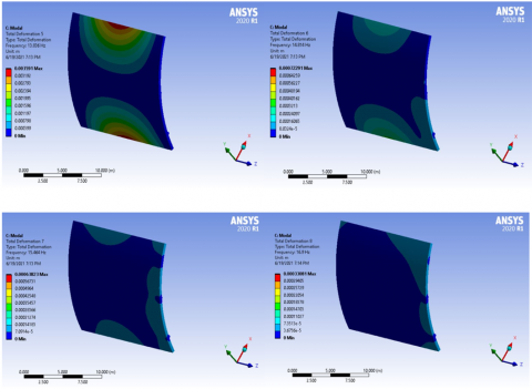
Figure 20. The mode shapes of Haditha Dam spillway radial gate for first, second, third and fourth modes
Figure 21. The mode shapes of Haditha Dam spillway radial gate for fifth, sixth, seventh and eighth modes
Many researchers have attempted to investigate the hydraulics properties of the spillway with a physical and numerical model. With the development of the CFD technique, the hydraulic parameters for a spillway flow can be determined more easily and quickly. It is an economical and cost-effective technology and provides better viewing of the results. The numerical model was carried out using the realisable k– ɛ model by Fluent software. The results of the numerical model were compared with the physical model of the Haditha Dam spillway. The main conclusions of the present study are as follows:
The flow parameters like water depth and pressures obtained by the numerical model of Fluent for the turbulent model were in good agreement with the physical model results.
The numerical model can be used to analyse or design hydraulic structures with high accuracy in different scenarios.
The numerical model can simulate cavitation over the spillway, and in the present simulation, the cavitation may occur at the end of the arching spillway to stretch downstream.
The numerical model is capable of simulated vibration and there is no danger for gate vibration in the present study, but it must be corresponding especially in hydropower dams because there is another source of the vibration from a turbine.
|
CFD |
computational fluid dynamics |
|
VOF |
volume of fluid |
|
RANS |
Navier- Stokes equation |
|
Greek symbols |
|
|
ρ |
Fluid density, kg. m-3 |
|
λ |
bulk viscosity coefficient |
|
q̇ |
rate of volumetric heat addition per unit mass |
|
µ |
dynamic viscosity, kg. m-1.s-1 |
|
ɛ |
dissipation of turbulence |
|
Subscripts |
|
|
v |
vector of velocity, m.s-1 |
|
e |
internal energy per unit mass |
|
t |
Time, s |
|
Cg |
discharge gated coefficient |
|
g |
gravity acceleration |
[1] Rajaa, A.I., Kamel, A.H. (2020). Performance study of fluent-2D and flow-3D platforms in the CFD Modeling of a flow pattern over ogee spillway. Anbar J. Eng. Sci., 8(4): 317-328.
[2] Daneshkhah, A.R., Vosoughifar, H.R. (2011). Investigation of the effect of design head on the flow profile of ogee spillways using finite volume analysis. Proc., 10th Hydraul. Hydraul. Conf. Rasht, Iran.
[3] Kamel, A., Abdulhameed, I. (2016). Study the effect of spillway locations on the hydraulic properties of spillway. Cienc. e Tec. Vitivinic.,31(5): 90-106.
[4] Ho, D.K.H., Riddette, K.M. (20210). Application of computational fluid dynamics to evaluate hydraulic performance of spillways in Australia. Aust. J. Civ. Eng., 6(1): 81-104. https://doi.org/10.1080/14488353.2010.11463946
[5] U.S.A.C. of Engineers. (1990). Hydraulic Design of Spillways. Engineer manual 1110-2-1603. US Government Printing Office Washington, DC, 1990.
[6] U.S.B. of Reclamation, Design of Small Dams. US Department of the Interior, Bureau of Reclamation, 1987.
[7] Erpicum, S., Tullis, B.P., Lodomez, M., Archambeau, P., Dewals, B.J., Pirotton, M. (2016). Scale effects in physical piano key weirs models. J. Hydraul. Res., 54(6): 692-698. https://doi.org/10.1080/00221686.2016.1211562
[8] Imanian, H., Mohammadian, A. (2019). Numerical simulation of flow over ogee crested spillways under high hydraulic head ratio. Eng. Appl. Comput. Fluid Mech., 13(1): 983-1000. https://doi.org/10.1080/19942060.2019.1661014
[9] Salazar, F., San-Mauro, J., Celigueta, M.Á., Oñate, E. (2020). Shockwaves in spillways with the particle finite element method. Comput. Part. Mech., 7(1): 87-99. https://doi.org/10.1007/s40571-019-00252-1
[10] Runchal, A.K. (20212). The future of CFD and the CFD of the future. Comput. Therm. Sci. An Int. J., 4(6): 1-10. http://dx.doi.org/10.1615/ICHMT.2012.CHT-12.10
[11] Zeng, J., Zhang, L., Ansar, M., Damisse, E., González-Castro, J.A. (2017). Applications of computational fluid dynamics to flow ratings at prototype spillways and weirs. II: Framework for planning, data assessment, and flow rating. J. Irrig. Drain. Eng., 143(1): 4016073. http://dx.doi.org/10.1061/(ASCE)IR.1943-4774.0001113
[12] Abdullah, O.S., Kamel, A.H., Khalil, W.H. (2021). Numerical and experimental modelling of small hydropower turbine. J. Adv. Res. Fluid Mech. Therm. Sci., 80(1): 112-127.
[13] Alhashimi, D.R.S.A.M. (2013). CFD modeling of flow over ogee spillway by using different turbulence models. Int. J. Sci. Eng. Technol. Res., 2: 1682-1687.
[14] Daneshfaraz, R., Kaya, B., Sadeghfam, S., Sadeghi, H. (2014). Simulation of flow over ogee and stepped spillways and comparison of finite volume and finite element methods. J. Water Resour. Hydraul. Eng., 3(2): 37-47.
[15] Kumcu, S.Y. (2017). Investigation of flow over spillway modeling and comparison between experimental data and CFD analysis. KSCE J. Civ. Eng., 21(3): 994-1003. http://dx.doi.org/10.1007/s12205-016-1257-z
[16] Uçar, M., KUMCU, Ş.Y. (2018). Comparison of physical modeling and cfd simulation of flow over spillway in the arkun dam. 5 th International Symposium on Dam Safety At: Istanbul 2018.
[17] Barzegari, M., Foumani, R.S., Isari, M., Tarinejad, R., Alavi, S.A. (2019). Numerical methods in civil engineering numerical investigation of cavitation on spillways. A Case Study : Aydoghmush Dam, pp. 1-9.
[18] Damarnegara, S., Wardoyo, W., Perkins, R., Vincens, E. (2020). Computational fluid dynamics (CFD) simulation on the hydraulics of a spillway. IOP Conf. Ser. Earth Environ. Sci., 437(1). https://doi.org/10.1088/1755-1315/437/1/012007
[19] Nohani, E. (2015). Retracted: Numerical simulation of the flow pattern on morning glory spillways. Int. J. Life Sci., 9(4): 28-31. https://doi.org/10.3126/ijls.v9i4.12671
[20] Dehdar-Behbahani, S., Parsaie, A. (2016). Numerical modeling of flow pattern in dam spillway’s guide wall. Case study: Balaroud dam, Iran. Alexandria Eng. J., 55(1): 467-473. https://doi.org/10.1016/j.aej.2016.01.006
[21] Parsaie, A., Dehdar-Behbahani, S., Haghiabi, A.H. (2016). Numerical modeling of cavitation on spillway’s flip bucket. Front. Struct. Civ. Eng., 10(4): 438-444. https://doi.org/10.1007/s11709-016-0337-y
[22] Mohammed, J.R., Noori, B.M.A., Hussein, I.A. (2017). Modeling of the hydraulic performance of ogee spillway using computational fluid dynamics (CFD). J. Univ. Duhok, 20(1): 638-653. https://doi.org/10.26682/sjuod.2017.20.1.56
[23] Parsaie, A., Moradinejad, A., Haghiabi, A.H. (2018). Numerical modeling of flow pattern in spillway approach channel. Jordan J. Civ. Eng., 12(1): 1-9.
[24] Daneshfaraz, R., Minaei, O., Abraham, J., Dadashi, S., Ghaderi, A. (2019). 3-D Numerical simulation of water flow over a broad-crested weir with openings. ISH J. Hydraul. Eng., 1-9. https://doi.org/10.1080/09715010.2019.1581098
[25] de Morais, V.H.P., Gireli, T.Z., Vatavuk, P. (2020). Numerical and experimental models applied to an ogee crest spillway and roller bucket stilling basin. Rev. Bras. Recur. Hidricos. https://doi.org/10.1590/2318-0331.252020190005
[26] Fadaei, K.E., Barani, G.A. (2014). Numerical simulation of flow over spillway based on the CFD method. ransactions on Civil Engineering (A), 21(1): 91-97.
[27] Li, J., Ameen, A.M.S., Mohammad, T.A., Al-Ansari, N., Yaseen, Z.M. (2018). A systematic operation program of a hydropower plant based on minimising the principal stress: Haditha dam case study. Water (Switzerland), 10(9): 1-19. https://doi.org/10.3390/w10091270
[28] Sissakian, V.K., Adamo, N., Al-Ansari, N., Knutsson, S., Laue, J., Elagely, M. (2018). A comparative study of mosul and haditha dams, Iraq: Geological conditions. J. Earth Sci. Geotech. Eng., 8(2): 1792-9660.
[29] Moscow, haditha project on the euphrates river, vol. XI, no. technical design ,Laboratory studies, book 1. 1978.
[30] Wendt, J.F. (2008). Computational Fluid Dynamics: an Introduction. Springer Science & Business Media, 2008.
[31] Tey, W.Y., Yutaka, A., Nor Azwadi, C.S., Goh, R.Z. (2017). Governing equations in computational fluid dynamics: Derivations and a recent review. Prog. Energy Environ., 1: 1-19.
[32] Fais, L.M.C.F., Genovez, A.I.B. (2009). Discharge rating curve and scale effects correction in Morning Glory Spillways. in Advances in Water Resources and Hydraulic Engineering, Springer, 2009, pp. 2041-2046. https://doi.org/10.1007/978-3-540-89465-0_350
[33] Sarwar, M.K., Ahmad, I., Chaudary, Z.A., Mughal, H.U.R. (2020). Experimental and numerical studies on orifice spillway aerator of Bunji Dam. J. Chinese Inst. Eng. Trans. Chinese Inst. Eng. A, 43(1): 27-36. https://doi.org/10.1080/02533839.2019.1676652
[34] Yildiz, A., Yarar, A., Kumcu, S.Y., Marti, A.I. (2020). Numerical and ANFIS modeling of flow over an ogee-crested spillway. Appl. Water Sci., 10: 90. https://doi.org/10.1007/s13201-020-1177-4
[35] Aydin, M.C., Isik, E., Ulu, A.E. (2020). Numerical modeling of spillway aerators in high-head dams. Appl. Water Sci., 10(1): 1-9. https://doi.org/10.1007/s13201-019-1126-2
[36] Jahad, U., Al-Ameri, R., Chua, L., Das, S. (2018). Investigating the effects of geometry on the flow characteristics and energy dissipation of stepped spillway using two-dimensional flow modelling. Proc. - Int. Assoc. Hydro-Environment Eng. Res. (IAHR)-Asia Pacific Div. Congr. Multi-Perspective Water Sustain. Dev. IAHR-APD 2018, 1: 289-296.
[37] Irzooki, A.S.A., Hoobi, R., Mohammed, J.R. (2016). Computational fluid dynamics modeling of flow over stepped spillway. Tikrit J. Eng. Sci., 23(3): 1-11. http://dx.doi.org/10.25130/688
[38] Hirsch, C. (2007). Numerical computation of internal and external flows: The fundamentals of computational fluid dynamics. Elsevier, 2007.
[39] Committee, C.F.D.T. (2019). Computational Fluid Dynamics: Applications in Water, Wastewater, and Stormwater Treatment. https://doi.org/10.1061/9780784415313
[40] ANSYS, I. (2013). ANSYS Fluent Theory Guide. U.S.A.: ANSYS, Inc. is certified to ISO 9001:2008, 2013.
[41] Greenshields, C.J. (2018). OpenFOAM user guide Version 6. OpenFOAM Found., 2018.
[42] Kolkman, P.A. (1976). Flow-induced gate vibrations: Prevention of self-excitation. Computation of dynamic gate behaviour and the use of models. Ph. D. Thesis, 1976.
[43] Thang, N.D., Naudascher, E. (1986). Vortex-excited vibrations of underflow gates. J. Hydraul. Res., 24(2): 133-151. https://doi.org/10.1080/00221688609499327
[44] Lee, S.O., Seong, H., Kang, J.W. (2018). Flow-induced vibration of a radial gate at various opening heights. Eng. Appl. Comput. Fluid Mech., 12(1): 567-583. https://doi.org/10.1080/19942060.2018.1479662
[45] Shen, H.S., Wang, H. (2014). Nonlinear vibration of shear deformable FGM cylindrical panels resting on elastic foundations in thermal environments. Composites Part B: Engineering, 60: 167-177. https://doi.org/10.1016/j.compositesb.2013.12.051